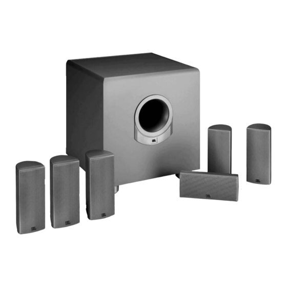
Summary of Contents for JBL SCS160SI
- Page 1 Surround Cinema Series SCS150SI Models: SCS160SI SCS180.6S Home Theater Speaker Systems SERVICE MANUAL JBL Consumer Products 250 Crossways Park Dr. Woodbury, New York 11797 Rev4 10/2005...
-
Page 2: Table Of Contents
EXPLODED VIEW……..……….………………………………….8 TEST SET-UP AND PROCEDURE……..……….………..……..9 PCB DRAWINGS…………… ……..………………..…….……..10 MECHANICAL/SATELLITE PARTS LIST………………………16 ELECTRICAL PARTS LIST ……………...……………….…….17 IC/TRANSISTOR PINOUTS……..…….…………………..…….22 SCHEMATICS PACKING..………….………………………………..…………….26 SCS150SI/SCS160SI/SCS180.6S Systems Frequency Response 30Hz – 20kHz (–6dB) Satellites Recommended Power 10 – 100 watts Impedance 8 ohms nominal Sensitivity... -
Page 3: Detailed Specifications
SCS150SI/SCS160SI/SCS180.6S 150W Powered Sub/ Plate Amp LINE VOLTAGE Yes/No Hi/Lo Line US 120vac/60Hz 108-132 Asia 100vac/50Hz 90-110 Parameter Specification Amp Section Type (Class AB, D, other) Load Impedance (speaker) 4 Ohms Rated Output Power 150 Watts THD@ Rated Power 0.08 % THD @ 1 Watt 0.1 %... -
Page 4: Connections
SCS150SI/SCS160SI/SCS180.6S S P E A K E R C O N N E C T I O N S Connection Tips To use the binding-post speaker terminals on the subwoofer, unscrew the colored collar until the pass through hole in the center post is visible under the collar. -
Page 5: Speaker Level
SCS150SI/SCS160SI/SCS180.6S Dolby Pro Logic (Non-Digital) – Speaker Level Use this installation method for Dolby Pro Logic appli- cations (not Dolby Digital, ® or other digital processing), where the receiver/processor does not have a subwoofer output, or a volume-controlled preamp (line-) level output: Connect your receiver or amplifier’s front left and right... -
Page 6: Dolby Pro Logic (Non-Digital) - Line Level
SCS150SI/SCS160SI/SCS180.6S Dolby Pro Logic (Non-Digital) – Line Level Use this installation method for Dolby Pro Logic appli- cations (not Dolby Digital, DTS or other digital processing), where the receiver/processor is equipped with a subwoofer output, or a volume-controlled preamp (line-) level output: –... -
Page 7: Operation
“Auto” position). When your receiver or amplifier is off, or HIGH LEVEL – – IMPORTANT: CONNECT STRIPED WIRE TO RED ( ) SPEAKER TERMINAL. JBL, Incorporated A Harman International Company This area is designed to become quite warm during normal operation... -
Page 8: Basic Troubleshooting
Web site at www.jbl.com for further information. If there is no sound from the center speaker: • Check all wires and... -
Page 9: Exploded View
SUB150/160/180 CABINET FOOT – MAIN PLASTIC BODY FOOT – RUBBER BOTTOM FOOT SCREW T4*30L 10” WOOFER AMPLIFIER/WOOFER SCREWS T4*20L SUB150/160/180 AMPLIFIER (SCS150SI) WI5447 “ (SCS160SI) 321-ABS-00008 “ (SCS180.6) 321-ABS-00008-0LA (SCS150SI) WI5448 “ (SCS160SI/180.6) 321-ABS-00009 Part Number NOT FOR SALE 06-T43005... -
Page 10: Equipment Needed
6) Connect one pair of speaker cables to Speaker Level input terminal (IN) on UUT. Cables should be connected to an integrated amplifier fed by the signal generator. 7) Turn on generator and adjust so that speaker level input at the amplifier is 2.0V, 50 Hz. Turn LEVEL control full clockwise. -
Page 11: Pcb Drawings
SCS150SI/SCS160SI/SCS180.6S... - Page 12 SCS150SI/SCS160SI/SCS180.6S...
- Page 13 SCS150SI/SCS160SI/SCS180.6S...
- Page 14 SCS150SI/SCS160SI/SCS180.6S...
- Page 15 SCS150SI/SCS160SI/SCS180.6S...
- Page 16 SCS150SI/SCS160SI/SCS180.6S...
-
Page 17: Center Channel
SCS150SI/SCS160SI/SCS180.6S SCS150SI Description SUBWOOFER Amplifier Ass’y Not for Sale SUB 150/SUB160/SUB180 Cabinet Not for Sale 10” Woofer DCR = 3.4 ohms ±10% 25MF12DZB-DW02 Rubber Foot Pad wi5448 Foot wi5447 SATELLITES Complete SCS150SI/SAT-1 Woofer 32PF55JE-LW02 Tweeter 29DM15NA-FT03 Foot wi5213-g Grille xc035006... -
Page 18: Electrical Parts List
SCS150SI/SCS160SI/SCS180.6S SUB150/SUB160/SUB180 Electrical parts List Part# Reference Designator Input/Power Amp PCB Semiconductors 197131n4148 D102,103,104,105,143,201-208, 211,212,214,215,216,301,302 19915000335 D213 19915000625 D101 19915001605 D502 192027c1815gr Q108,109,113,201,206-208,301,302 192027c2235y Q111 192028a1015gr Q101,107,112 1921672n5551 Q114,115 1921682n5401 Q503 19006m4558d U203 19016tl074cn U201,202,301 192161tip31c Q501 192162tip32c Q502 19510204hgw... - Page 19 SCS150SI/SCS160SI/SCS180.6S Part# Reference Designator Input/Power Amp PCB 11016221j26 R144 11016222j26 R102 11016223j26 R238,247,255,256,263,316 11016273j26 R223,237 11016333j26 R310 11016393j26 R151 11016472j26 R200,207,258 11016473j26 R106,129,219,249,250,251 11016474j26 R127,312 11016512j26 R210,211 11016513j26 R224 11016562j26 R152 11016621j26 R160 11016751j26 R315 11016755j26 R313 11016913j26 R203-206 116161002f26...
- Page 20 SCS150SI/SCS160SI/SCS180.6S Part# Reference Designator Input/Power Amp PCB 1353105m50 C228 1353106m50 C201,202,206,213,219,231,241,243, 251,253,319,321 1353107m10 C114,115 1353107m16 C234 1353107m35 C507,508 1353225m50 C509 1353226m16 C304 1353226m50 C225,505,506 1353227m16 C118,233 1353476m16 C318 Power Amp Class D Module part# 012-7500-00022 RECOMMENDED: REPLACE ENTIRE MODULE Resistors...
- Page 21 SCS150SI/SCS160SI/SCS180.6S Part# Reference Designator Power Amp Class D Module part# 012-7500-00022 RECOMMENDED: REPLACE ENTIRE MODULE Semiconductors 19016tl072dts 19209124126qs Q1,4,5 19209139066rs Q2,8 19209210376qs Q7,9 19209215146rs Q3,6 19703rls4148s D1,2,3,4,5,6 19915000563s Z1,2 19915001203s Z5,6 19915001503s Z3,4 192232irf9640 192233irf640 Miscellaneous 1759f40hr2 12214121m4191 12214350j4180 06-t3085020...
- Page 22 SCS150SI/SCS160SI/SCS180.6S Part# Reference Designator Misc./Mechanical 723a125 723a125-1 723b125 723b125-1 723j125 TO SPK WIRE 06-t30804 R/P TO H/S-2,R/P TO PCB-2 06-t31004 SPK-2,RCA-2 06-t41208 TO 700rc800a 104ds15000 104sub15000 16210060003 J104 TO W201 PIN4 16210082007 SW TO FUSE HOLDER 16250129001 W201 1740rca108gb JK201...
-
Page 23: Integrated Circuit Diagrams
SCS150SI/SCS160SI/SCS180.6S Integrated Circuit Diagrams 4558 / TLO72 DUAL OP AMP, U203, IC1 TRANS, PNP, 2N5401 TAP, TO-92, Q503 TRANS, PNP, TAP, 2SA1015GR, 2SC1037K, 2SA1514K Q3,6,7,9,101,107,112 OPAMP, QUAD 14P DIL TL074 TIP31C NPN, TIP32C PNP, Q501,502 1. G 2. D 3. S... - Page 24 SCHEMATICS SCS150SI/SCS160SI/SCS180.6S...
- Page 25 SCS150SI/SCS160SI/SCS180.6S...
- Page 26 SCS150SI/SCS160SI/SCS180.6S...
-
Page 27: Packing
SCS150SI/SCS160SI/SCS180.6S SATELLITE STYROFOAM SCS160SI/SCS180.6S – 431-000-00937 WIRE SET (SATS & CENTER) SCS150SI – SAL5019 SCS160SI/SCS180.6S – 370-000-00087 WIRE SET (SUB IN/OUT) SCS150SI – SAL063-1 SCS160SI/SCS180.6S – 370-000-00069 WARRANTY CARD SCS150SI – AT5160 SCS160SI/SCS180.6S – 405-000-00258 OUTER CARTON SCS150SI – WG5270 SCS160SI –...


Need help?
Do you have a question about the SCS160SI and is the answer not in the manual?
Questions and answers