
Related Manuals for Main Multipoint BF


Summary of Contents for Main Multipoint BF
- Page 1 Please leave these instructions with the user MULTIPOINT BF Gas Fired Balanced Flue Water Heater User Operating, Installation and Servicing Instructions...
- Page 2 Protective equipement (e.g. gloves) should be worn as necessary. User Information Your Main Multipoint BF is designed to meet all relevant standards. Main provide a 12 month guarantee on the appliance. The guarantee operates from the date installation is completed for the customer who is the original owner.
-
Page 3: Table Of Contents
Contents Section page User’s Operating Instructions ........4 General Layout .............. 5 Technical Data ............... 6 Dimensions and Fixings ..........7 General Information ............8 Installation Regulations ..........8 Siting the Appliance ............. 9 Siting the Flue Terminal ..........10 Air Supply .............. -
Page 4: User's Operating Instructions
1. User’s Operating Instructions Pilot ignition: 1. Depress slide control and hold it in. - Off 2. Press the - Pilot igniter repea- tedly until the - Burner pilot is alight. - Igniter 3. Release the slide control approx 10 seconds after pilot lights. -
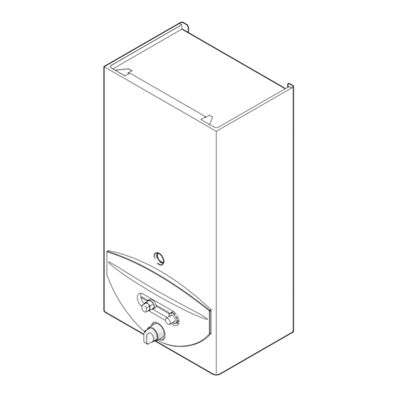
Page 5: General Layout
22 Water filter 23 Diaphragm 24 Piezo igniter 25 Slide control 26 Pilot gas button 27 Gas valve 28 Main gas valve 29 Pilot gas pipe 30 Temperature limiter 31 Flue hood 32 Water valve Fig. 4 6 720 607 090... -
Page 6: Technical Data
3. Technical Data TABLE 1 - GENERAL Natural Gas Se-duct* Gas category Appliance Type Minimum rated output 7 kW 7 kW Maximum rated output 23 kW 20.7 kW Rated input (Net) 25.5 kW 23 kW Gas rate (CV 34 MJ/m 2.9 m 2.6 m Inlet pressure... -
Page 7: Dimensions And Fixings
4. Dimensions and Fixings Fig. 5 6 720 607 090... -
Page 8: General Information
5. General Information 6. Installation Regulations 5. 1 GENERAL INSTALLATION Warning - Check the information on the data plate is If the appliance is to be fitted into a compartment, the compatible with local conditions. compartment must conform to the requirements of BS 6798. Do not place anything on top of the appliance. -
Page 9: Siting The Appliance
7. Siting the Appliance 7. 1 The appliance is NOT suitable for external installation. This appliance is suitable for installation in conjunction with a “SEDUCT” flue system that complies with the requirements of BS 5440 - 1 2000 & IS 813:2002. The appliance is suitable for replacement onto four stud flue terminals as shown (check dimensions on page 7). -
Page 10: Siting The Flue Terminal
8. Siting the Flue Terminal See Fig. 8. The flue must be installed as specified in BS 5440:Part 1. If the terminal discharges onto a pathway or passageway, check that the combustion products will not cause a nuisance and that the terminal will not cause an obstruction. -
Page 11: Air Supply
9. Air Supply The appliance does not require a separate vent for combustion air. The appliance may be installed in an unvented compartment. There must be sufficient clearance around the appliance to allow proper circulation of air. The clearences required for operation will normally be adequate. Refer to BS 6798 and BS5440:2 for additional information. - Page 12 11.5 Unfasten the two retaining screws and lift the case clear. 11.6 Remove the flue hood from the appliance by undoing the three fixing screws and lift the hood clear. 11.7 Place the appliance on its side, obtain the flue terminal sealing strip from the kit and fit into the recess around the flue aperture in the back of the appliance.
-
Page 13: Commissioning
. Fully open any hot water tap. The Fig. 13 - Gas control slide - Pilot ignition position main burner should light. 12.6 Check the dynamic inlet gas pressure is 20 mbar. If the pressure is not correct then check the gas supply to the appliance. -
Page 14: Inspection And Servicing
The servicing must be carried out by a competent person. Before commencing any service operation turn off the gas supply at the main gas service cock. Ensure that the appliance is cool. Access for Servicing Pull off the fascia and undo the two fixing screws. - Page 15 (fig. 20). Turn on the gas supply at the main gas service cock and check for gas soundness BS 6891 while the appliance is running.
-
Page 16: Replacement Of Parts
Any servicing or parts replacement must be carried out by a competent person. Use only genuine Manufacturer’s Parts. Before commencing servicing or parts replacement turn off the gas supply at the main gas isolation valve and ensure that the appliance is cool. 14. 1... - Page 17 Disconnect the pilot gas pipe and thermocouple from the gas valve. Pull off the two cables from the rear of the igniter unit. Release the main gas pipe union connection below the combustion chamber and lift the valve clear complete with the control panel.
-
Page 18: Fault Finding
No spark. Clean or replace the electrode, Piezo unit or cable. Gas pressure low. Check the inlet and burner pressure. Main burner will not light. Gas isolation valve partially closed. Open the gas isolation valve. Low water rate. Check the water rate. - Page 19 17. Notes 6 720 607 090...
- Page 20 GENERAL ENQUIRIES (GB) 08706 060 780 TECHNICAL (GB) 08706 049 049 SERVICE (GB) 08706 096 096 LITERATURE REQUEST (GB) 08706 060 623 TECHNICAL (IE) 1850 560 570 Baxi Potterton A Trading Division of Baxi Heating U.K. Ltd Brownedge Road Bamber Bridge Preston Lancashire PR5 6SN www.baxipotterton.co.uk Comp N 5111036 –...
Need help?
Do you have a question about the Multipoint BF and is the answer not in the manual?
Questions and answers
can you turn off the water supply for long periods of time without damaging the boiler?