Table of Contents
Advertisement
Quick Links
Advertisement
Table of Contents

Summary of Contents for B & G B&G
- Page 1 Zeus Multi-function Display Installer Manual English...
-
Page 2: Preface
Translation of the Documentation, the English language version of the Documentation will be the official version of the Documentation. This manual represents the product as at the time of printing. Navico Holding AS and its subsidiaries, branches and affiliates reserve the right to make changes to specifications without notice. -
Page 3: Declaration Of Conformity
1999/5/EG. Par la présente, Navico Holding AS déclare que ce Z8, Z12 est conforme aux exigences essentielles et aux autres dispositions de la directive 1999/5/CE qui lui sont applicables. -
Page 4: Table Of Contents
Contents Preface ....................1 Introduction ..................6 About this Manual ................6 Conventions ................... 6 Important Safety and Warning Information ......... 6 Check the Parts ................7 Overview .................... 8 Installing the Display ................10 Mounting location ................10 Panel Mount ................. 11 Bracket Mount ................ - Page 5 Ethernet ..................28 Dual and Multi Station NMEA0183 Wiring ................30 Video In ..................31 Video Out ..................32 Connecting BroadBand™ Radar ............33 Connecting HD Radar ..............34 Connecting BSM1 Broadband Echosounder ........35 Commission the System..............36 Turning on the system for the fi rst time ........... 36 Operating the Menu System ............
- Page 6 Drawings .................... 53 Z8 Dimensions ................53 Z12 Dimensions ................54 Spare Parts ..................55 Zeus Spare Parts ................55 Zeus Optional Accessories .............. 55 Compatible BSM-1 Transducers SimNet Accessories ............... 56 Ethernet Cables (yellow) Ethernet Cables (RJ45) Repeat Screens Video Cables for Repeat Screens Specifi...
-
Page 7: Introduction
The information in this manual at the time of printing is correct to the best of our knowledge. Navico can not be liable for any inaccuracies or missing information. Due to the constant improvement of Navico’s products. Navico cannot be liable for changes between the product and the manual. Refer to www.bandg.com for the latest manuals, addendum’s and software updates. -
Page 8: Check The Parts
Check the Parts Packaged Parts List 8“ Display unit Z8 Bezel PN location specifi c 000-10406-001 12 “ Display unit Z12 Bezel PN location specifi c 000-10405-001 Z8 Sun cover Z8 Gasket 000-10408-001 Z12 Sun cover Z12 Gasket 000-10407-001 Z8 Mounting bracket Bracket knobs 000-00136-001 000-00138-001... -
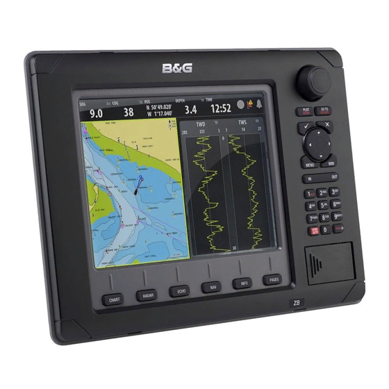
Page 9: Overview
Overview PLOT GO TO MARK VESSEL MENU PQRS WXYZ STBY AUTO CHART RADAR ECHO INFO PAGES Description Direct Access Keys (DAK). Provide direct access to a page. Repeated presses of each DAK cycles through several different pages that relate to the DAK PLOT/MARK key. - Page 10 Description Power. For power input 12 or 24 V DC input (see power section), Power control (see Power Control section) and external alarm (see External Alarm section. Video In. Supplied cable provides two composite video inputs (see Video In section) and one RS422 port (NMEA0183 TX, RX) see NMEA0183 Wiring section.
-
Page 11: Installing The Display
Installing the Display Mounting location Choose the mounting locations carefully before you drill or cut. The display should be mounted so that the operator can easily use the controls and clearly see the display screen. Be sure to leave a direct path for all of the cables. The display screen is high- contrast and anti-reflective, and is viewable in direct sunlight, but for best results install the display out of direct sunlight. -
Page 12: Panel Mount
Panel Mount 5 mm (0.20”) CLEARANCE HOLE TO SUIT M4 MACHINE SCREW OR DRILL PILOT HOLE TO SUIT SELF TAPPING SCREW CUTOUT 265 mm (10.40”) Check dimensions before cutting PRODUCT OUTLINE 25 mm (1.00”) 265 mm (10.40”) 285 mm (11.20) Attach the fl... -
Page 13: Bracket Mount
Bracket Mount An alternative to flush mounting the Z8 or Z12 is to bracket mount the unit. This method has the advantage that the display can easily be removed when not in use. The display may be tilted for best possible viewing angle when bracket mounted. Press the ratchet washers into the Loosely screw securing knobs to the bracket. - Page 14 Drill a pilot hole for the fi ve screws Secure 5 the bracket to the surface and an optional hole large enough for the cables to emerge from. Connect the cables. Attach the bezel. Firmly clip the front bezel in place. Slide the display into the mounting bracket and secure in place with the bracket knobs.
-
Page 15: System Architecture
System Architecture This section explains how the Zeus connects to other devices as part of a system. The Zeus has a highly scalable system architecture. A system can consist of a basic stand alone chart plotter, or expand to a networked, multi-display system connected to a wide range of accessories. -
Page 16: Data Bridging
Data Bridging Supported NMEA0183 sentences entering the system are bridged (converted) to • SimNet/NMEA2000 and distributed on the SimNet backbone for all other displays to Certain SimNet /NMEA2000 PGNs (messages/sentences) are bridged across to • NMEA0183 to be available as an output from any Zeus display Ethernet to SimNet. -
Page 17: Wiring Information
Wiring Information Typical System 16 | Wiring Information... -
Page 18: Standard Connections
Standard Connections NMEA0183 Devices Zeus Display NMEA0183 Device Video / Comms - NMEA0183 H3000 Zeus Display H3000 H-Link (USB) Deckman Navigation Software Deckman Zeus Display H3000 Navigation Software H-Link (USB) Video / Comms - NMEA0183 Wiring Information | 17... -
Page 19: Wtp3
WTP3 Deckman Serial Zeus Display Navigation Software Interface WTP3 Video / Comms - NMEA0183 Ethernet Network 18 | Wiring Information... -
Page 20: Wiring The Zeus Display
Wiring the Zeus Display Wiring guidelines Most installation problems are caused by shortcuts taken with system cables. When wiring the Zeus, follow the guidelines below. Don’t Do This Do This Don’t make sharp bends in the cables Do make drip and service loops Don’t run cables in a way that allows water Do tie-wrap all cables to keep them secure to fl... -
Page 21: Power
Power The Zeus displays can be powered by either 12 V or 24 V DC. Displays are protected against reverse polarity, under voltage and over voltage. The supplied power cable has a four core cable used for:- power into the system (Red and Black wires) •... - Page 22 Black Black Red (FUSE) Red (FUSE) Yellow Yellow Blue Blue No Connect 12 - 24 V DC 12 - 24 V DC No Power Control Auto Power on Display will turn on and off when the Display will turn on when power is applied power button on the front of the unit to the display.
- Page 23 Power Control Table Slave Master Can turn on by own PWR button YES * Can turn off by own PWR button YES * Can turn on other devices Can be turned on or off by another device Can turn off entire system if started by an ignition switch Can have more than one on a system * If Power control wire is not connected.
-
Page 24: External Alarm
External Alarm An external alarm can be connected to one or more displays on the network. The external alarm can be a small peizo buzzer connected directly or a horn siren connected via a relay. Alarms are configured globally in the system i.e they can be configured on one display and seen, heard and acknowledged from all displays. -
Page 25: H-Link
H-Link H-Link is B&G’s protocol for comprehensive and efficient interfacing of the B&G H3000 processor range used in conjunction with Zeus chartplotters and external PC navigation programmes. There are two versions of H-Link depending on the H3000 processor you are using. B&G H-Link LT H-Link LT is a version of the B&G data communication protocol providing an interface to Zeus displays. -
Page 26: Simnet
SimNet SimNet is a data network based on NMEA2000 CAN bus technology that makes interconnection and integration of B&G and NMEA2000 products simple. SimNet permits the exchange of data between the interfaced products and enables the flow of commands and instructions between the various SimNet and NMEA2000 compatible products. -
Page 27: Planning And Installing A Simnet Backbone
NMEA2000 devices can be connected to the SimNet Network providing they: • are NMEA2000 certified meet the CE, FCC regulations with a SimNet adapter cable do not exceed the SimNet load specification (please refer to separate document B&G SimNet Installation Manual (20222006) Planning and Installing a SimNet Backbone Plan the SimNet backbone carefully For part numbers refer to SimNet Accessories. - Page 28 12 V DC SimNet drop cable SimNet power SimNet terminator A slightly larger system below. Power is connected at one end using terminated power cable. A second terminator is required at the end of the backbone. SimNet drop cable SimNet backbone SimNet power SimNet terminator 12 V DC...
-
Page 29: Ethernet
Ethernet The Zeus system uses an Ethernet network to interconnect high bandwidth devices such as other Zeus displays, radar and echo sounder. Each Zeus display has three network ports with 5 pin connectors. Ethernet network cables have orange connectors that are retained by a bayonet type locking collar. -
Page 30: Dual And Multi Station
Dual and Multi Station If there is more than one display it is recommended to use a network expansion port Network Expansion Port POWER NETWORK Broadband Radar™ Broadband Sounder™ Alternatively you can connect two or more Zeus displays without an network expansion port. -
Page 31: Nmea0183 Wiring
Connecting to Navico HD Radar / Older Sirius Weather module (RJ45 Ethernet connectors) Ethernet Adapter cable yellow 5 pin to Navico RJ45 Ethernet cable. Navico RJ45 cable. refer Ethernet Cables Refer to Ethernet Cables (RJ45) for part (yellow). numbers. NMEA0183 Wiring To exchange NMEA0183 data, the Zeus display units have a NMEA0183 communication port. -
Page 32: Video In
Video In Connect up to two composite video cameras to each display unit using the supplied Video / Data cable. This connects to the VIDEO IN port on the rear of the display. Video inputs are only displayed locally and are not distributed to other displays. Only one video input can be viewed at a time. -
Page 33: Video Out
Video Out The Zeus display has a DVI-I Video connector. Connect a second display to replicate what is on the screen of the Zeus display. A DI10 display can only interface to Z8 and DI15 only to Z12 due to fixed resolutions. The MO19 or other scalable monitor or TV can be connected to either Z8 or Z12 MO19 Or third party monitor... -
Page 34: Connecting Broadband™ Radar
Connecting BroadBand™ Radar SimNet Network Power Scanner cable White RX+ Brown RX- AT10HD NMEA0183 to SimNet Converter Heading Only NMEA0183 10 Hz Heading (e.g Gyro, Sat Compass) Alternative: NMEA0183 heading Description Zeus Display. BroadBand™ Radar system for Zeus. Includes parts C,D and E. Scanner cable. -
Page 35: Connecting Hd Radar
Connecting HD Radar 2 kW 12 V DC ONLY 4 kW & 6 kW 12 or 24 V DC 10 kW & 25 kW 24 V DC ONLY Scanner Ethernet AT10HD AA010070 RX+ White RX- Brown AT10HD cable(cut off plug) RX- White RX+ Black/White NMEA0183 10 Hz Heading... -
Page 36: Connecting Bsm1 Broadband Echosounder
Connecting BSM1 Broadband Echosounder Description Zeus Display BSM-1 Broadband Echosounder module Ethernet cable yellow 5 pin see Ethernet cables yellow for more cable length options. Cable can be connected directly to Zeus or via a Network Expansion Port see Ethernet. 12 or 24 V DC Transducer: See compatible transducer list. -
Page 37: Commission The System
Commission the System Turning on the system for the fi rst time Before starting the system for the first time, check the following; Check radar is physically clear to rotate • Leave a HD pulse radar in standby for 30 minutes before transmitting for the first •... -
Page 38: Commissioning Checklist
Commissioning Checklist The Zeus has a number of advanced features which can be configured through the settings menu. It is recommend you become familiar with the operation of the unit using the default settings before making any changes to these menus. Settings menus will vary depending on the optional sensors and devices attached. -
Page 39: System Settings Menu
System settings menu To access the system settings menu press MENU Language Language used on menus and dialog boxes Step 1 Step 2 Step 3 Notes The display will need to be restarted for change to take effect PLOT GOTO PLOT GOTO PLOT... -
Page 40: Echosounder Setup
Echosounder Setup Depth Offset Is a value that can be entered to make the depth on the Echo page represent either depth below the transducer or depth below the surface. A) Depth below Keel value: Is the distance from transducer to the keel: Enter a negative value. -
Page 41: Radar Setup
Water Speed Averaging Averages water speed by measuring your speed at a selected interval of time. Water speed intervals range from one to thirty seconds. If you select five seconds, your water speed will be recorded every five seconds, then averaged. Calibration range: 1-30 seconds. - Page 42 Radar Transmit, Standby or off Press Radar function button to MENU display the radar Press Menu to bring up radar options To make radar adjustments. select item to • PLOT GOTO MENU MARK VESSEL adjust Setting value is Adjust the setting To confi...
-
Page 43: Data Setup
Data Setup Data set up is required on initial start up of the system, or if any part of the SimNet or NMEA 2000 network has been changed or replaced. From Network in the main system settings menu you can Select SimNet / NMEA2000 data sources either automatically •... - Page 44 each of these categories a display can be set to receive data from sources as part of the Default group or receive the source data independently from the group (None) The example below shows the available options for position sources, and that the GS15 GPS is used by all displays with group selection set to B&G.
- Page 45 SimNet Groups The SimNet Group function is used to control parameter settings, either globally or in groups of units. It groups parameter settings such as backlighting, units and alarms. The function is used on larger vessels where several units are connected via the SimNet network.
-
Page 46: Damping
Damping Controls how quickly instruments respond to changes in values from sensors. Damping can be used for heading, wind, boat speed and depth instruments. Increasing the damping applies more averaging or smoothing of the data update rate on the instrument or display. Damping settings are applied to SimNet displays and Instruments belonging to particular damping SimNet Groups. -
Page 47: Serial Port Setup
Serial Port Setup Configure the serial port to match the NMEA0183 device that it is connected to. Baud Rate (common for input and output) Step 1 Step 2 Step 3 PLOT GOTO MARK VESSEL PLOT GOTO Select OK MARK VESSEL Select Baud Rate NMEA 0183 Output... -
Page 48: Fuel
Fuel If the vessel has an NMEA2000 interface to its engines and fuel tanks. Zeus can display the following fuel consumption information: Fuel used since last fill • Fuel used on current trip • Fuel used during the season • Calibration of the tanks is needed to display accurate fuel levels. -
Page 49: Diagnostics
Diagnostics NMEA2000 Diagnostics Bus State: Indicates if SimNet backbone is operating: Check power: Check termination RX Overfl ows / Overruns greater than 0 could indicate the software is very busy and unable to keep up with incoming messages. RX / TX Errors: CAN interface error counters. Count up when there are errors on the CAN bus, and down when things are Ok. -
Page 50: Check Gps Signal
Check GPS Signal Press direct access key PAGES (3) If interfaced to H3000 Instruments via H-Link this feature is available via, Settings Menu, System, Satellites. System Backup A backup of all the Zeus settings such as page layouts and custom instruments can be made at any time, and can be stored on the Zeus or transferred to a USB stick or SD Card Creating a System Backup File... -
Page 51: Restore A System Backup File
Restore a System Backup File Restoring data from a backup file will overwrite all existing data and settings with the data and settings saved to the backup file. STEP 1: STEP 2: Select the desired backup fi le. press Highlight yes, press ‘Enter’ to confi rm the ‘Menu’... - Page 52 Ethernet Module Software Version Software version : CA1637C Example below shows upgrading a ZG50 GPS Antenna. Steps 1 - 3 are the same for Zeus display upgrades. Menu Item Step 1 Step 2 Step 3 Copy upgrade fi les Press function Select Memory card Press Menu on to a USB Stick...
-
Page 53: Screen Capture
Screen Capture It is possible to capture a snap shot of the current screen Step 1 Step 2 Enable screen capture Create desired screen to capture Step 3 PQRS WXYZ STBY AUTO Short press on PWR button to capture screen shot File Transfer Step 1 Step 2... -
Page 54: Drawings
Drawings Z8 Dimensions 221.0 mm (8.70”) 212.0 mm (8.35”) Drawings | 53... -
Page 55: Z12 Dimensions
Z12 Dimensions 273.0 mm (10.75”) 266.0 mm (10.47”) 54 | Drawings... -
Page 56: Spare Parts
Spare Parts Zeus Spare Parts Part Number Description 000-10406-001 Bezel,Zeus,Z8 000-10405-001 Bezel,Zeus,Z12 000-10408-001 Sun cover Z8 000-10407-001 Sun cover Z12 000-00136-001 Z8 Mounting bracket 000-00137-001 Z12 Mounting bracket 000-00138-001 Mounting bracket knobs & washers (pair L/R) 000-00143-001 Flush mount kit 000-00139-001 Rotary knob 000-00140-001... -
Page 57: Compatible Bsm-1 Transducers
Compatible BSM-1 Transducers Part Number Description 000-0136-02 Airmar P319, plastic, low profi le, thru hull 50/200 KHz, depth/temp, 7 pin blue connector 000-0136-03 Airmar P79, plastic, In-Hull 50/200 KHz, depth only, 7 pin blue connector 000-0136-04 Airmar B60, bronze, low profi le, thru hull, 50/200 KHz, depth/ temp, 12°... -
Page 58: Ethernet Cables (Yellow)
24005894 SimNet termination plug 44172278 SimNet termination In-Line joiner 24005902 2 m (6.6 ft) SimNet power w/termination 24005910 2 m (6.6 ft) SimNet power w/o termination 24005936 AT10 Universal NMEA0183 converter 24005944 AT15 Active T-connector, IS15 24005928 SimNet cable protection cap 24005729 SimNet to Micro–C (male) cable that connects a SimNet product to a NMEA2000 network... -
Page 59: Specifi Cations
Bulgarian, Asian language pack Plotter Characteristics Display modes Head-up*, Course-up, North-up (*external heading or COG) Cartography Embedded: Navico Insight HD (US) Navionics (Rest of World) Navionics Platinum Plus via SD Card Latitude Limit 83º North, 85º South Alarms Position, Off-Course, Waypoint Radius, Arrival, Anchor, Anchor... -
Page 60: Supported Nmea0183 Sentences
Supported baud rates 4,800, 9,600, 19,200, 38,400 Note. Port will transmit and receive at the set baud rate Ethernet 10/100 base Ethernet, three ports Max number of dis- 6 in any combination Z8 or Z12 plays External connectors x 1 USB and x 1 SD (front) External Connectors Power (power control, ext. -
Page 61: Nmea 2000 Pgn List
NMEA 2000 PGN List NMEA 2000 PGN Receive 59392 ISO Acknowledgement 130310 Environmental Parameters 59904 ISO Request 130311 Environmental Parameters 60928 ISO Address Claim 130312 Temperature 60928 ISO Address Claim 130313 Humidity 126208 ISO Command Group Function 130314 Actual Pressure 126992 System Time 130576... -
Page 62: Nmea2000 Pgn Transmit
NMEA2000 PGN Transmit 126208 ISO Command Group Function 126992 System Time 126996 Product Info 127237 Heading/Track Control 127250 Vessel Heading 127258 Magnetic Variation 128259 Speed, Water referenced 128267 Water Depth 128275 DistanceLog 129025 Position, Rapid Update 129026 COG & SOG, Rapid Update 129029 GNSS Position Data 129283... - Page 63 *988-0186-01A* www.bandg.com...
Need help?
Do you have a question about the B&G and is the answer not in the manual?
Questions and answers