Table of Contents
Advertisement
Quick Links
SERVICE MANUAL
LED TV
Model No. 32D3005
MSD3393LU Chassis
WARNING
This service information is designed for experienced repair technicians only and is not designed for use by the general public.
It does not contain warnings or cautions to advise non-technical individuals of potential dangers in attempting to service a product.
Products powered by electricity should be serviced or repaired only by experienced professional technicians. Any attempt to service or repair
the product or products dealt with in this service information by anyone else could result in serious injury or death.
©2013 Qingdao Haier Electronics Co., Ltd.
All rights reserved. Unauthorized copying and distribution is a violation of law.
Advertisement
Table of Contents

Related Manuals for Haier 32D3005


Summary of Contents for Haier 32D3005
- Page 1 Products powered by electricity should be serviced or repaired only by experienced professional technicians. Any attempt to service or repair the product or products dealt with in this service information by anyone else could result in serious injury or death. ©2013 Qingdao Haier Electronics Co., Ltd. All rights reserved. Unauthorized copying and distribution is a violation of law.
-
Page 2: Table Of Contents
Service Manual Model No.: 32D3005 CONTENTS Chapter 1. General Information 1-1. Document Information ..............3 1-2. General Guidelines..............3 1-3. Important Notice.................3 1-3-1. Follow the regulations and warnings ............. 3 1-3-2. Be careful to the electrical shock ............3 1-3-3. Electro static discharge (ESD)..............3 1-3-4. - Page 3 Service Manual Model No.: 32D3005 4-3-2. Connector definition ................15 4-4. LCD Panel ..................16 Chapter 5. Installation Instructions 5-1. Accessories ................18 5-2. External Equipment Connections..........19 Chapter 6. Operation Instructions 6-1. Front Panel Controls..............20 6-2. Back Panel Controls ..............21 6-3. Setting Up Your Remote Control ..........22 Chapter 7.
-
Page 4: Chapter 1. General Information
Service Manual Model No.: 32D3005 Chapter 1. General Information 1-1. Document Information Document format: Adobe PDF Author: shouwang.wen Compiler: 1-2. General Guidelines When servicing, observe the original lead dress. If a short circuit is found, replace all parts which have been overheated or damaged by the short circuit. -
Page 5: About Lead Free Solder (Pbf)
Service Manual Model No.: 32D3005 components commonly are called Electrostatically Sensitive (ES) Devices. The following techniques should be used to help reduce the incidence of component damage caused by electros static discharge (ESD). Electrostatically Sensitive (ES) Devices Some semiconductor (solid-state) devices can be damaged easily by static electricity. Such components commonly are called Electrostatically Sensitive (ES) Devices. - Page 6 Service Manual Model No.: 32D3005 1. Always unplug the receiver AC power cord from the AC power source before: a. Removing or reinstalling any component, circuit board module or any other receiver assembly. b. Disconnecting or reconnecting any receiver electrical plug or other electrical connection.
-
Page 7: Ordering Spare Parts
Service Manual Model No.: 32D3005 12. Use only a grounded-tip soldering iron to solder or unsolder ES devices. 13. Use only an anti-static type solder removal device. Some solder removal devices not classified as "anti-static" can generate electrical charges sufficient to damage ES devices. - Page 8 Service Manual Model No.: 32D3005 Caution: A “caution ” is used when there is danger that the reader, through incorrect manipulation, may damage equipment, loose data, get an unexpected result or has to restart(part of) a procedure. Warning: A “warning” is used when there is danger of personal injury.
-
Page 9: Chapter 2. Specification
Service Manual Model No.: 32D3005 Chapter 2. Specification 2-1. Specification list Model 32D3005 Screen Size 32" Aspect Ratio 16:9 Resolution 1366x768 Brightness (cd/m²) Contrast 1000:1 Response Time (ms) Angel of View H:170°, V:160° Color Display 16.7M OSD Language English,French,Spanish. Color System... -
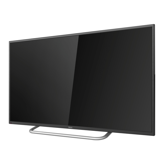
Page 10: External Pictures (Four Faces)
Service Manual Model No.: 32D3005 2-2. External pictures (four faces) Front Side Up Side... - Page 11 Service Manual Model No.: 32D3005 Right Side Back Side...
-
Page 12: Chapter 3. Disassemble And Assemble
Service Manual Model No.: 39D3005 Chapter 3. Disassemble and Assemble 3-1. 32D3005 3-1-1. Remove the Stand 3-1-3. Remove the power-main board. 1. Remove the six screws indicated with red circles. 2. Then remove the side metal board and down metal board. -
Page 13: Remove The Remote Control Board
Service Manual Model No.: 32D3005 3-1-6. Remove the Remote Control Board And the Key Board Remove the Remote Control Board and the Key Board indicated byred circle in below picture. -
Page 14: Chapter 4. Location Of Controls And Components
Service Manual Model No.: 32D3005 Chapter 4. Location of Controls and Components 4-1. Board Location A Board B Panel Parts number Description DH1TKPM0002M A Board power-main board 712-315E7-X6251 B Panel LCD Panel... -
Page 15: Mainboard
Service Manual Model No.: 32D3005 4-2. Mainboard 4-2-1. Function Description Process signal which incept from exterior equipment then translate into signal that panel can display. 4-2-2. Connector definition IR & Key Interface LED Backlight interface CN804/CN805 Pin number Signal name... -
Page 16: Power Supply Module
Service Manual Model No.: 32D3005... -
Page 17: Lcd Panel
Service Manual Model No.: 32D3005 4-3. LCD Panel 32D3005 Backlight Unit LVDS CONNECTOR CNF1... - Page 18 Service Manual Model No.: 32D3005...
-
Page 19: Chapter 5. Installation Instructions
Service Manual Model No.: 32D3005 Chapter 5. Installation Instructions 5-1. Accessories Batteries Remote Control... -
Page 20: External Equipment Connections
Service Manual Model No.: 32D3005 5-2. External Equipment Connections Antenna Connection Connect a DVD Player or VCR to Your TV Connect your aerial to the back of the TV into the ANTENNA IN socket. There are two ways in which you can connect a DVD player or VCR to your TV. -
Page 21: Chapter 6. Operation Instructions
Service Manual Model No.: 32D3005 Chapter 6. Operation Instructions 6-1. Front Panel Controls 5 VOL+ Press to increase the volume. POWER Press to turn the TV on and off. 6 MENU Press to select the main menu. TV channel down. -
Page 22: Back Panel Controls
Service Manual Model No.: 32D3005 6-2. Back Panel Controls Earphone output Coax output Audio in input Video/Y in input PbPr IN input PC Audio input input input HDMI1 input 10 HDMI2(MHL) input 11 HDMI3(ARC) input 12 USB IN input... -
Page 23: Setting Up Your Remote Control
Service Manual Model No.: 32D3005 6-3. Setting Up Your Remote Control When using the remote control, aim it towards the remote sensor on the TV. POWER. INPUT. Shortcut button. HOME; Program Number Channel selection. RECALL button. VOL+/VOL-: Volume selection. CH /CH : Channel selection. -
Page 24: Chapter 7. Electrical Parts
Service Manual Model No.: 32D3005 Chapter 7. Electrical Parts 7-1. Circuit Diagram RB124 RB144 RB125 RB145 RB126 RB146 CB118 RB127 RB147 TB101 DB102 Vbridge RB141 DB103 RB142 CB114 RB128 RB129 SGND RB130 RB143 CB117 BB101 BB102 RB101 DB106 QB101 CB116... - Page 25 PWM-DIM TEST PWM/ADJ PWM-DIM PWM-DIM 0ohm 1Kohm 0.1uF-16V CD11 MP1470GJ-Z LD2 SCD54TL-4R7M 5V_STB 10uF-16V 10uF 18Kohm 470uF-16V 0.1uF 470uF 5V_STB WPM2341A-3/TR 5V_M QM32 100Kohm RD24 100Kohm 3K3ohm 0.1uF-16V 10pF CM32 3V3_STB CM31 4K7ohm 0.1uF RM34 0.1uF 10Kohm 100Kohm POW_EN 10Kohm LMBT3904LT1G 5V_M LC1117CLTRAD...
- Page 26 1.15V_STB 1V8_DDR CD10 CL16 MSD3393LU 3V3_STB +3_3V_AU 3V3_STB +3_3V_PLL FCM1005KF FCM1005KF CL17 CL18 HDMI2_RX1_N LED_RED RX1N_B SAR1 HDMI2_RX1_P RX1P_B SAR0 HDMI2_RX2_N RX2N_B AVDD_MOD 3V3_STB HDMI2_RX2_P RX2P_B DP_P1 3V3_STB AVDD_MOD DM_P1 HDMI3_RXC_N USB0_DP RXCN_A DP_P0 HDMI3_RXC_P USB0_DM RXCP_A DM_P0 HDMI3_RX0_N RESET_H RX0N_A RESET PH_EN...
- Page 27 4K7ohm 4K7ohm NC/AVLC18S02003 NC/AVLC18S02003 AVLC18S02003 75ohm 75ohm 75ohm 75ohm 75ohm 75ohm NC/10pF NC/10pF NC/10pF 12Kohm 12Kohm NC/10pF 100ohm NC/100uF-16V 330pF NC/AVLC18S02003 NC/AVLC18S02003 NC/AVLC18S02003 10uF-10V NC/AIES12U020R2 NC/0ohm 12Kohm 12Kohm NC/AIES12U020R2...
- Page 29 0ohm RA31 AMP-MUTE AMP_MUTE/ 470uF-25V 100ohm AMPVCC RA50 NC/SK34A-SMA-F CA43 CA49 4K7ohm NC/470uF-16V NC/10uF 0.1uF 15V_IN AVCC 10ohm 15V_IN AMP_MUTE/ PVCCL FAULT PVCCL RA21 0.22uF-16V AMP-L1 LINP BSPL 100ohm 220ohm 0.22uF-16V 0.22uF-16V LINN OUTPL CA27 SCD54TL-220M NC/1000pF 0.47uF-16V 1000pF 47Kohm SCD54TL-220M 5V_M GAIN0...
- Page 30 HDMI HDMI 0.1uF-16V HDMI 0.1uF-16V 300Kohm 0.1uF-16V 1Kohm 10Kohm 10uF-10V...
-
Page 31: Circuit Diagram
Service Manual Model No.: 32D3005 7-2 . Wiring Connection Diagram... -
Page 32: Chapter 8. Measurements And Adjustments
Service Manual Model No.: 32D3005 Chapter 8. Measurements and Adjustments 8-1. Service Mode 8-1-1.How to enter into Service Mode The way to the factory mode menu: Step 1: Press Menu, Step 2: Press “8893”, System will be into the factory mode menu when 2 steps above are done. -
Page 33: General Setting
Service Manual Model No.: 32D3005 8-2-2. GENERAL SETTING 1)Init Flash; 2)Uart Enable:Choose on or off in Uart Enable; 3)Dbg Message Enable: Choose on or off in Dbg Message Enable; 4)Test Pattern: Choose the Pattern picture; 5)Dynamic Contrast: Choose on or off in Dynamic Contrast;... -
Page 34: Sound
Service Manual Model No.: 32D3005 8-2-4. SOUND Adjust the values of Sound Mode, Volume Curve,Audio Output and True Volume in different source. 8-2-5. Panel Setting 1)LVDS Bit Mode: choose the Bit; 2)LVDS MAP: choose the MAP; 3)LVDS ODD/Even: choose ODD or Even;... -
Page 35: Software Update
Service Manual Model No.: 32D3005 8-3. Software Update 8-3-1. MSD3393LU software update 1. Copy the software files to a USB disk on the root directory; 2. Insert the USB disk when the AC power is off; 3. Turn on the AC power in turn to begin;... -
Page 36: Chapter 9. Trouble Shooting
Service Manual Model No.: 32D3005 Chapter 9. Trouble shooting 9-1. Simple check Verify if the television is properly plugged No picture/ No sound Verify if the television is properly supplied power Verify if electricity is available. Verify if correct signals are input... -
Page 37: Mainboard Ic Introduction
Service Manual Model No.: 32D3005 9-2. Mainboard IC Introduction Top view... - Page 38 Service Manual Model No.: 32D3005 Bottom view...
- Page 39 Service Manual Model No.: 32D3005 1.Mainchip—MSD3393LU(U1) 2. Audio Amplifier—TPA3110D2PWPR (UA1) 3.Main Flash Memory—GD25Q32BSIG (UF1) 4.DC/DC convertor 5V-1.8V for MSD3393LU (U1)—LC1117CLTRAD (UL2) 5.voltage convertor 5V to 3.3V_STB —LC1117CLTR33 (UL1) 6.voltage convertor 5V to 1.15V_STB —LC3406CB5TR (UD1) 7.voltage convertor 12V to 5V_STB —MP1470GJ-Z...
-
Page 40: Mainboard Failure Check
Service Manual Model No.: 32D3005 9-3. Mainboard Failure Check No picture but have sound Check the power output Change the Power Board There’s something wrong Check the CN2 (BLO) with FRC Backlight on/off Verify if the DC/DC convertor can output the... - Page 41 Service Manual Model No.: 32D3005 No sound but have picture Verify if the speakers are Change the speakers broken Verify if the main board has the Check the corresponding audio right input ,according to the source input circuit you connect.
- Page 42 Service Manual Model No.: 32D3005 No sound No picture Verify if the Power has Change the 5Vstb output Power supply Verify if CN4 Pin3/4 has 5V Change Power board input Verify if CN2 Pin1 has 12V Change Power board input...
- Page 43 Service Manual Model No.: 32D3005 Poor sound Poor sound Verify if sound system is Change sound correct . system For ease of use, recommend that customer format the picture and sound settings in the automatic option. Updata the software and Still having make the reboot;...
- Page 44 Service Manual Model No.: 32D3005 No color for some channel program (black and white) No color for some chann el program (black and w hite) Verify if the same Check out of picture and sound problem exists in other system of this channel...
- Page 45 Service Manual Model No.: 32D3005 How to know whether the Power board is broken? Check if the power cord co Reconnect the power cord with the nnect well? outlet or Power board. Check if the Power board Replace the Power board pls.
-
Page 46: Pannel Failure
Service Manual Model No.: 32D3005 9-4. Pannel Failure Failure Mode... - Page 47 Service Manual Model No.: 32D3005...
- Page 48 Service Manual Model No.: 32D3005...
- Page 49 Service Manual Model No.: 32D3005...
- Page 50 Service Manual Model No.: 32D3005...
- Page 51 Sincere Forever Haier Group Haier Industrial Park, No.1, Haier Road 266101, Qingdao, China http://www.haier.com Printed in China...