
Related Manuals for Clarke MIG102NG


Summary of Contents for Clarke MIG102NG
- Page 1 WARNING: Read these instructions before using the machine NO GAS MIG WELDER MODEL NO: MIG102NG PART NO: 6015600 OPERATION & MAINTENANCE INSTRUCTIONS LS0214...
-
Page 2: Introduction
GUARANTEE This CLARKE product is guaranteed against faulty manufacture for a period of 12 months from the date of purchase. Please keep your receipt as proof of purchase. -
Page 3: Table Of Contents
CONTENTS INTRODUCTION ............... 2 GUARANTEE ..............2 ENVIRONMENTAL RECYCLING POLICY ......2 CONTENTS ............... 3 GENERAL SAFETY INSTRUCTIONS ........4 SAFETY SYMBOLS ............7 THE WELDING SHIELD ............7 ELECTRICAL CONNECTIONS .......... 8 UNPACKING ..............9 Opening The Cover.............. 9 OVERVIEW ............... -
Page 4: General Safety Instructions
GENERAL SAFETY INSTRUCTIONS WARNING: WHEN USING ELECTRICAL TOOLS, BASIC SAFETY PRECAUTIONS SHOULD ALWAYS BE FOLLOWED TO REDUCE THE RISK OF FIRE, ELECTRIC SHOCK AND PERSONAL INJURY WARNING: READ ALL THESE INSTRUCTIONS BEFORE ATTEMPTING TO OPERATE THIS PRODUCT AND KEEP THESE INSTRUCTIONS IN A SAFE PLACE. ELECTRIC SHOCK insulated for safety. - Page 5 • The welding arc can cause serious one is looking before striking an burns. Avoid contact with skin. arc. • Sparks and molten metal are • Wear hearing protection if ejected during welding. Take required. precautions to prevent fire. • Allow the weld to cool. Hot metal •...
- Page 6 • NEVER attempt any electrical or mechanical repair unless you are a qualified technician. If you have a problem with the machine contact your local CLARKE dealer. • Never use or store in a wet/damp environment. • NEVER continue to weld, if, at any time, you feel even the smallest electric shock.
-
Page 7: Safety Symbols
When replacing the glass panels, only use parts supplied by Clarke International. The dark panel is a certified, specific optical class, and should not be exchanged for any other type. The clear glass panel should be replaced when it becomes badly pitted. -
Page 8: Electrical Connections
ELECTRICAL CONNECTIONS WARNING! READ THESE ELECTRICAL SAFETY INSTRUCTIONS THOROUGHLY BEFORE CONNECTING THE PRODUCT TO THE MAINS SUPPLY. Before switching the product on, make sure that the voltage of your electricity supply is the same as that indicated on the rating plate. This product is designed to operate on 230VAC 50Hz. -
Page 9: Unpacking
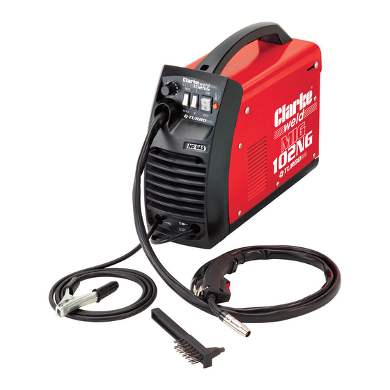
UNPACKING Any damage or deficiency should be reported to your CLARKE dealer immediately. The components include the following: • 1 x Gasless MIG Welder (torch and earth clamp attached) • 2 x 0.9 mm Torch Tips (one installed in the torch) •... -
Page 10: Overview
OVERVIEW DESCRIPTION NO DESCRIPTION Handle Hammer/Brush Tool Control Panel Torch Earth Clamp Torch Hose Parts & Service: 020 8988 7400 / E-mail: Parts@clarkeinternational.com or Service@clarkeinternational.com... -
Page 11: The Control Panel
THE CONTROL PANEL 1. Thermal overload light. If the duty cycle is exceeded as a result of welding too long with a high current, the amber overload light will illuminate and the welder will turn off. When the welder has cooled down (approx. 5 to 10 minutes), the light will go out, the power will be restored and welding can recommence. -
Page 12: Preparation For Use
MOUNTING THE WELDING WIRE SPOOL Warning: Ensure that the welder is not connected to the mains supply. NOTE: Spools of welding wire are available from your Clarke Dealer. 1. Open the cover, by sliding the top back ,and then lift the cover open as shown on page 9. -
Page 13: Threading The Wire
5. Pull the roller off the drive spindle. • The groove size is stamped on the corresponding side of the roller. Select the groove size according to the size of the wire you are using and put the roller back on the spindle with your chosen side facing you. - Page 14 6. Lower the cover and slide it forward to close. 7. Pull off the torch shroud with a twisting movement, then unscrew the contact tip. 8. Connect the welder to the power supply and switch ON. 9. Set the ‘WIRE FEED’ rotary control on the front panel to position 7 or 8 and squeeze the trigger on the torch body.
-
Page 15: Mig Welding Principles
MIG WELDING PRINCIPLES MIG (Metal Inert Gas) welding allows you to fuse together two similar metals without altering the properties of the metal. A consumable wire electrode is continuously fed through the welding torch that is fitted with a concentric gas nozzle. the wire is connected to a high voltage supply which creates an electric arc between the electrode (the wire) and the workpiece. -
Page 16: Thermal Overload
5. In order to produce a satisfactory weld, the controls may be fine tuned as required. This will come with practice. NOTE: MIG welding is an acquired skill, it is strongly advised that, if you are not fully familiar with this type of welding, you practice on a piece of material with the same characteristics as your workpiece, until you are satisfied with the result, and you have fine tuned your welder to produce a satisfactory weld. -
Page 17: Duty Cycle
35 amps the machine may be used for 6 minutes (60%) in any 10 minute period. ACCESSORIES The following are some of the accessories available from your CLARKE dealer. Please quote the part numbers shown below: PART DESCRIPTION... -
Page 18: Maintenance
To keep the contact tip free from spatter, we recommend the use of anti- spatter spray (Part number: 6000715) available from your CLARKE dealer. Torch shroud: The torch shroud must also be kept clean and free from spatter. Build-up of spatter inside the gas cup can cause a short circuit at the contact tip which will result in expensive machine repairs. -
Page 19: Rating Plate
RATING PLATE Name and address of manufacturer Load Voltage symbol Model number, part number Energy Input symbol Batch number Rated supply voltage Single phase transformer-rectifier Rated maximum supply current British Standards applied Maximum effective supply current Welding process This symbol indicates that the unit is suitable for carrying out welding operations in an environment which has an increased risk of electric... -
Page 20: Troubleshooting
TROUBLESHOOTING Your CLARKE MIG Welder has been designed to give long and trouble free service. If, however, having followed the instructions in this booklet carefully, you still encounter problems, the following points should help identify and resolve them. PROBLEM CAUSE... - Page 21 If you have any problems which cannot be resolved by reference to the above, or if you require spare parts for your welder please contact your local Clarke dealer. Parts & Service: 020 8988 7400 / E-mail: Parts@clarkeinternational.com or Service@clarkeinternational.com...
-
Page 22: Specifications
Rated Max Input Current 16 A The details and specifications contained herein, are correct at the time of going to print. However, CLARKE International reserve the right to change specifications at any time without prior notice. DUTY CYCLE The duty cycle determines the machine ‘down time’. i.e 10% means 1 minutes operation followed by 9 minutes of rest. -
Page 23: Declaration Of Conformity
DECLARATION OF CONFORMITY Parts & Service: 020 8988 7400 / E-mail: Parts@clarkeinternational.com or Service@clarkeinternational.com...
Need help?
Do you have a question about the MIG102NG and is the answer not in the manual?
Questions and answers