
Related Manuals for Spiegelberg HDM 26.1/FV500

Summary of Contents for Spiegelberg HDM 26.1/FV500
- Page 1 Spiegelberg: ICP-Monitor HDM 26.1/FV500 HDM 26.1/FV503 Operating Instructions Monitoring Technology for Brains...
-
Page 2: Ec Declaration Of Conformity
Spiegelberg: EG-Konformitätserklärung EC Declaration of Conformity Die Spiegelberg (GmbH & Co.) KG erklärt als Hersteller in alleiniger Verantwortung, dass die im folgenden genannten Produkte die Anforderungen der Richtlinie 93/42/EG erfüllen. Das Qualitätsmanagementsystem entspricht den Forderungen der Norm EN ISO 13485:2003 + AC:2009. -
Page 4: Table Of Contents
Contents Safety instructions Indication and Method Monitor Operation Cleaning Connections Faults Technical Specifications Approved Accessories Symbols used... -
Page 5: Safety Instructions
Safety Instructions The ICP-Monitor and the accom- Attention panying probes are designed for the Grounding reliability can only be measurement of intracranial achieved if the device is connected pressure. The manufacturer accepts to an equivalent power cord marked responsibility for the safety, „hospital grade“... -
Page 6: Indication And Method
Indication and Method The ICP-Monitor and the probes are The intracranial pressure is intended for the monitoring of transmitted across the thin pouch intracranial pressure in the ventricle, wall to the air volume in the pouch in the parenchyma, subdurally, or and transformed into an electric epidurally. - Page 7 Connect the power cord to the monitor and to a power outlet. The power control lamp indicates mains operation. After placement of probe the tube connector is inserted into the monitor socket and fastened by a slight clockwise turn. The soft material of the connector guarantees air-tightness.
-
Page 8: Cleaning
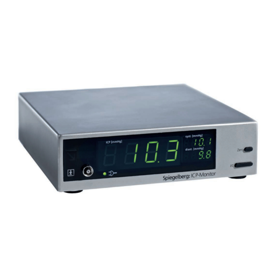
On the digital display the mean ICP is shown in mmHg. Systolic and diastolic ICP are also displayed. Cleaning After removal of the power cord Attention the unit can be wiped off with a Unplug the power cord damp rag using a common prior to cleaning. -
Page 9: Connections
Connections Connection of a Patient Monitor To connect a patient monitor the connecting cable is inserted into the socket of the ICP-Monitor marked Monitor and connected to the pressure transducer input of the patient monitor. Zero Adjustment of the Patient Monitor Push the button marked Zero. -
Page 10: Faults
Faults The air-tightness of the Air-Pouch system is checked regularly. If a leak is detected, the red warning indicator shows alarm. When the leak is removed the red warning indicator disappears and the measurement is continued. If the leak has not been removed after one minute, in addition to the alarm display a chirp sound is emitted. -
Page 11: Technical Specifications
Technical Specifications HDM 26.1/FV500 HDM 26.1/FV503 Measurement range -50 to +100 mmHg Operating voltage 230 V~, 50/60 Hz 115 V~, 50/60 Hz Current requirement 0,1 A at 230 V~ 0,2 A at115 V~ 125 mA T at 230 V~ Fuses... - Page 12 Pinout of RS 232 Socket Pinout of Monitor Socket 2: RxD 1: Uref Input 3: TxD 5: Analog Output 7: Gnd 6: Uref Output (2,5 V) 9: Analog Gnd. For use as a voltage output pins 1 and 6 are connected by a jumper.
-
Page 13: Approved Accessories
Approved Accessories Description CPP-Monitor CPP 21.x Compliance-Monitor CMP 27.x Spiegelberg-Probes SND 13.x.xx SND 32.x.xx Interconnect Cable for CPP 21.x or CMP 27.x KBL 21.005.00 Monitor Cables B.Braun/Lohmeier KBL 13.027.01 Criticare KBL 13.037.01 Datex-Cardiocap KBL 13.007.00/FV608 Datascope KBL 13.026.01 Digicare KBL 13.039.01 Dixtal KBL 13.042.01... - Page 14 Cables for Devices with Voltage Input BNC-Plug KBL 13.030.00/FV654 Banana Plug 4 mm KBL 13.031.00/FV653 Computer Cable RS 232 9-pin 150 cm KBL 13.033.00/FV656 25 cm KBL 13.033.01 Attention The ICP-Monitor must only be used with monitors and devices, that are CE-marked and approved as an electro-medical device.
-
Page 15: Symbols Used
Symbols used Attention Alternating current Fuse Equipotential Applied part type BF Mains control lamp Separate collection On / Off... - Page 16 Spiegelberg (GmbH & Co.) KG Tempowerkring 4 21079 Hamburg Germany Phone: +49-40-790-178-0 Fax: +49-40-790-178-10 0297 Email: info@spiegelberg.de http://www.spiegelberg.de Technical alterations reserved. © by Spiegelberg (GmbH & Co.) KG, 2006 Version: 4 / 2011-12-02...
Need help?
Do you have a question about the HDM 26.1/FV500 and is the answer not in the manual?
Questions and answers