Table of Contents
Advertisement
Quick Links
Download this manual
See also:
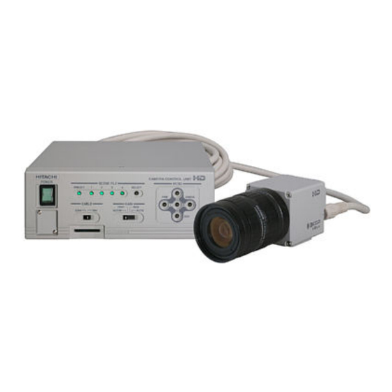
Operating Manual
3-CCD Color Camera
MODEL HV-HD201
OPERATION MANUAL
Please read this operation manual carefully for proper operation, and keep it for future reference.
Note:
The model and serial numbers of your product are important for you to keep for your convenience and protection. These
numbers appear on the nameplate located on the bottom of the product. Please record these numbers in the spaces provided below, and
retain this manual for future reference.
Model No.
Serial No.
Hitachi Kokusai Electric Inc.
Advertisement
Table of Contents

Related Manuals for Hitachi HV-HD201


Summary of Contents for Hitachi HV-HD201
-
Page 1: Ccd Color Camera
The model and serial numbers of your product are important for you to keep for your convenience and protection. These numbers appear on the nameplate located on the bottom of the product. Please record these numbers in the spaces provided below, and retain this manual for future reference. Model No. Serial No. Hitachi Kokusai Electric Inc. - Page 2 IMPORTANT SAFETY INSTRUCTIONS 1. Read Instructions 8. Accessories All the safety and operating instructions should Do not place this product on an unstable cart, be read before the product is operated. stand, tripod, bracket, or table. The product may fall, causing serious injury to a child or adult, 2.
- Page 3 19. Servicing 21. Replacement Parts Do not attempt to service this product yourself When replacement parts are required, be sure the as opening or removing covers may expose you to service technician has used replacement parts dangerous voltage or other hazards. Refer all specified by the manufacturer or have the same servicing to qualified service personnel.
- Page 4 erforderlich und dürfen nicht blockiert oder abgedeckt Stecker paßt nur in ein schuko-Steckdose. Dies werden. ist eine Sicherheitsmaßnahme. Wenn Sie den Die Öffnungen sollten niemals dadurch blockiert Stecker nicht in die Steckdose stecken können, so werden, daß, das Gerät auf ein Bett, ein Sofa, wenden Sie sich bitte an ihren Elektriker, damit er einen Teppich oder eine ähnliche Oberfläche die veraltete Schuts des Schutzkontaktsteckers...
- Page 5 21. Ersatzteile Wenn Ersatzteile erforderlich sind, darauf achten, daß der Wartungstechniker nur die vom Hersteller festgelegten Ersatzteile oder Teile mit gleichen Charakteristiken ursprünglichen Teile verwendet. Unautorisierte Ersatzteile können Feuer, elektrischen Schlag oder sonstige Gefährdungen verursachen. 22. Sicherheitsprüfung Bitten Sie den Wartungstechniker nach der Vollendung von Wartung oder Reparaturarbeiten an diesem Erzeugnis um die Durchführung von Sicherheitsprüfungen, um zu bestimmen, daß...
- Page 6 l’appareil et le protéger de toute surchauffe, et assurée par cette prise avec mise á la terre. ouvertures ne devront donc être ni 13. Protection du cordon d’alimentation obstruées ni recouvertes. Ne jamais obstruer les Acheminer les cordons d’alimentation de facon qu’on ne risque pas de marcher dessus ou de les ouvertures en placant l’appareil sur un lit, un sofa, un tapis ou toute surface similaire.
- Page 7 WARNING Changes modifications expressly approved Hitachi Kokusai Electric responsible for compliance could void the user’s authority to operate the equipment.
-
Page 8: Table Of Contents
Table of contents IMPORTANT SAFETY INSTRUCTUIONS AUTO WHITE IMPORTANT NOTICE SYSTEM Table of contents ID/TITLE Standard composition LENS Overview OTHER FUNCTION Features How to Attain Better images Notes to users White Balance Adjustment Name and function each section Real time Auto White Lens Auto Shading Correction Lens selection... -
Page 9: Standard Composition
Lens plug, E4-191J-100(JPE0001*) Operation Manual * Part code Overview The HV-HD201 is a three CCD HDTV camera It provides the digital output of high-definition combining high picture quality and high stability television format of four modes as well as the with the convenience of C mount optics. -
Page 10: Notes To Users
Observe that flammable objects, water or metal optimum performance from camera. do not enter the camera interior. These may Consult a Hitachi Kokusai Electric dealer for a lead to failure or accident. selection fine lenses according Do not modify the camera or use the camera with application. -
Page 11: Name And Function Each Section
Name and function each section It set the operational mode of HDTV. Please change it at power off state.) Please change it at power off state.) Outputs HD-SDI signal. Outputs Y/C signal. Outputs VBS signal. Sets the signal level to connect to O u t p u t s t h e a n a l o g p i c t u r e REMOTE terminal. -
Page 12: Lens
(see page 44). Also, as the lens iris approaches fully open, problems such as loss of resolution, shading Note: The HV-HD201 uses lens connector wiring and flare (overall image "white-out") can prescribed EIAJ (Electronic detract from picture quality. -
Page 13: Video Signal Type Lens Adjustment
Video signal type lens adjustment Adjustment is required after replacing the lens or (1) Set the lens ALC control fully toward the if using the camera for the first time. average (Av ) position. (2) If auto iris hunting occurs, reduce the Iris Gain setting. -
Page 14: Menu Screen Operation
Menu Screen Operation 1. Menu Structure For settings in the camera, the MAIN and SPECIAL menus are available. 1) MAIN Menu Structure Press the MENU button and MAIN MENU appears on the screen to indicate the main menu mode. Again press the MENU button to extinguish the menu and enter the direct mode. -
Page 15: Main Menu
AUTO WHITE [FILE1 ] SYSTEM ID/TITLE DATA SET SPEED :STANDARD ANALOG OUT SEL:HD TV :OFF HIGH LIMIT :10000K RGB/Y PB PR :RGB TITLE :OFF TITLE LOW LIMIT :2500K OUTPUT SYNC :SYNC DATA SET :NEXT [PUSH R] H PHASE 1234567890? : WHITE GATE :OFF GL IN... -
Page 16: Gain/Shutter
2) WHITE BALANCE : White balance mode Hue adjustment according to the color temperature of illumination so that a white image is picked up when the subject is white. • PRST 3200K : The white balance condition is optimized at a color temperature of 3200K. •... - Page 17 2) SHUTTER : Electronic shutter mode Used to reduce the amount of light to an appropriate level or reduce the degree of after-image by reducing the time of light reception per image. Using SHUTTER makes the image darker. (Note) If a blinking light source such as a fluorescent lamp is used, flicker occurs. Setting a slower shutter speed improves immunity to flicker.
-
Page 18: Detail
4. DETAIL: : : : DETAIL level setup Contours of the subject are emphasized to make the image easier to see. 1) DETAIL The DETAIL level can be set to in a range of -128 to 127. DETAIL [FILE 1] The degree of contour correction increases in the positive value setting, and it decreases in the negative value setting. -
Page 19: Auto Setup
5) ALC GATE SEL : Select ALC gate pattern Select pattern from among Modes 1, 2, 3, 4, 5 and 6. Use according to scene conditions. 検出領域 PATTERN 1 PATTERN 2 PATTERN 3 [FILE1 ] [FILE1 ] [FILE1 ] OVER RIDE OVER RIDE OVER RIDE SPEED... -
Page 20: Special Set
7. SPECIAL SET Special menu allows more detailed settings for the camera. 1) FILE SET : Change to FILE SET menu SPECIAL SET File operations, such as copying settings between scene files. FILE SET :NEXT [PUSH R] 2) LEVEL : hang to LEVEL menu. LEVEL :NEXT [PUSH R] MASKING... -
Page 21: Level
9. LEVEL Of R(red), G(green) and B(blue), the black and peak levels of the red and blue image signals can be changed for color adjustment. Because the setting for the green signal is fixed, this menu can be used to adjust the color temperature of the image. -
Page 22: Masking
10. MASKING Menu for adjustment selected color tone. Available 6 vector color masking and linear masking that can correct color tone with keeping picture brightness. MASKING [FILE1 ] 1) MASKING: MASKING ON/OFF setting [HUE][SAT] [LINEAR] Available (ON) or disable (OFF) toggle in this menu settings. 0 R-G: 0 Y-R: 0 R-B: 0... - Page 23 The following diagrams illustrate linear masking operations. 25) RG LINEAR: Color density and hue are changed in the direction of red-cyan axis. Blue and yellow do not change. 26) GB LINEAR: Color density and hue are changed in the direction of green-magenta axis. Blue and yellow do not change.
-
Page 24: Gamma/Knee
(All the masking menu settings become invalid in the OFF state.) 34) INITIALIZE : Returns MASKING menu settings to preset values. Simultaneously press L and R for about 2 seconds. 11. GAMMA/KNEE GAMMA/KNEE [FILE1 ] 1) GAMMA : Gamma ON/OFF Gamma correction is turned on/off. -
Page 25: Detail
7) KNEE POINT : Use L and R to set in the range -128 (smaller) to 127 (larger). Normally set to where gradation appears above 100% video level. (To accurately check the image level, measuring equipment such as an oscilloscope is necessary.) 8) WHITE CLIP : Sets white clip level Use L and R to set in the range of -128 (lower) to 127 (higher) clip level. -
Page 26: Color Detail
5) SOFT DETAIL W. : Limits the maximum DETAIL level in bright image portions. DETAIL may be excessively effective where changes in brightness are large. In this case, it may be possible to make the image natural by limiting the maximum DETAIL level. SOFT DETAIL W. allows you to set the maximum DETAIL level on the bright side (white). -
Page 27: Auto White
Range is -128 (soft) to 127 (sharp). Press both L and R for about 2 seconds to set to 0. 6) INITIALIZE : Returns COLOR DETAIL menu settings to preset values. Simultaneously press L and R for about 2 seconds. 14. -
Page 28: System
4) WHITE GATE : When WHITE GATE is ON, a detection gate is displayed dimly in white on the screen. • ON In real time auto white balance operation or execution of memory auto white balance, a video signal appearing in the window on screen is detected for white balancing. In the MENU mode, the window is presented over the video signal. -
Page 29: Id/Title
5) GL IN : Impedance changeover of input to the GL IN connector. • HIGH : The high impedance level is provided. • 75Ω : An impedance of 75 ohms is provided. Note: When power to the camera is turned off, the high impedance level is provided. So, do not use this function in a system where power is turned off for the camera unit only. -
Page 30: Lens
3) DATA SET : : : : The DATA SET screen comes up. : Enter an ID code consisting of three characters. Alphanumeric upper-case characters and a space character are permitted. TITLE : Enter a TITLE consisting of up to 12 characters. Alphanumeric upper-case characters, special symbols and a space character are permitted. -
Page 31: Other Function
Notes: 1) Before this adjustment, set AGC to OFF and Shutter to Off. Return the previous settings after adjusting. 2) Open Limit needs to be set properly for normal AGC coupled operation. 5) CLOSE Limit : (Lens Type is DC mode.) Observe the iris and adjust to precisely the largest value (smallest diameter). -
Page 32: How To Attain Better Images
How to Attain Better Images White Balance Adjustment Carry out white balance adjustment when the illumination condition (color temperature) is changed. Adjust the white balance when using the camera for the first time or after replacing the lens. 1. In the MENU mode, set up WHITE BAL: MEM. 2. -
Page 33: Realtime Auto White
Realtime Auto White The camera detects a white part in the image by itself, and its internal microcomputer automatically adjusts white balance in realtime. Use this function in case that the color temperature varies with time (e.g., from morning to day to night). 1. -
Page 34: Alc (Auto Level Control)
In combination of GAIN:AGC, SHUTTER:AES and AUTO IRIS, the following four kinds of ALC (auto level control) can be performed. This feature ensures stable video signal output according to a wide-range change in illumination. -
Page 35: Rc-Z3 Remote Control Panel
RC-Z3 Remote Control Panel All camera menu items can be operated remotely by connecting the RC-Z3 Remote Control Panel. Set camera’s rear panel switch RS-232C/RC-Z3 to RC-Z3 to connect the panel. Operation (1) Direct control The following items can be controlled directly as well as from the control panel. ・BAR/CAM ・ENABLE(ON/OFF) ・M.BLK... - Page 36 CONTROL switch 1 1 1 1 ・ON (red LED) : Normal camera control from. 26 26 26 26 ・LOCK (red LED) : All controls and switch RC-Z3 has locked at present settings, except IRIS M. BLK . Prevents accidental or unauthorized operation. 27 27 27 27 ・OFF (green LED): Operation inhibited from RC-Z3.
- Page 37 ・ REMOTE: Iris is adjusted by the iris control ・ MANUAL: Set the lens A/M switch to M and adjust the lens iris ring manually. Note: When using the video type lens, REMOTE and MANUAL function is ineffective in the HV-HD201...
-
Page 38: Menu Screen Composition
camera. 23 23 23 23 GAIN switch Sets the camera sensitivity. Press the switch upward to select the sensitivity in the sequence 0→3→6→9→12 dB→18 dB. The sensitivity setting is indicated by the combined GAIN LED indication. Note: When CAM MODE AUTO or AGC ON,the -3dB GAIN LED indicated all the time. 24 24 24 24 WHITE BALANCE mode select switch The white balance mode can be selected in the sequence PRESET →... -
Page 39: Connectors
Connectors MULTI connector (DMSH-15S) PLAG : Housing KEC-15P Pin No. Signal designation Pin contact JK-SP2140 R/R-Y OUT Cover JK-C151C G/Y OUT B/B-Y * Use No.4-40UNC plug retaining screws. UNREG +12V IN HD IN/HD OUT/ SYNC OUT VD IN/GL IN /VD OUT REMOTE connector (HR10A-7R-4S) LENS connector (D4-151N-100) Pin No. - Page 40 DC IN DC IN connector connector ( ( ( ( R03 R03- - - - R3M2 R3M2) ) ) ) S-VIDEO connector connector( TCS ( TCS- - - - 7547 7547- - - - 01401) 01401) DC IN DC IN connector connector R3M2...
-
Page 41: Specifications
Specifications HDTV system 4 mode 1) System 1080/59.94i, 1080/50i, 720/59.94p, 720/50p SDTV system 4 mode 576/50i(4:3), 576/50i(16:9), 480/59.94i(4:3), 480/59.94i(16:9) 1/2-size CCD image sensor (Image size are 1/2-size) 2) Picture elements Total pixels 1504 (H) × 1099 (V) Effective pixels 1440 (H) × 1080 (V) 6.98mm (H) ×... -
Page 42: Input/Output Signals
Input/Output Signals 1. Input signal conditions 1) Genlock input (MULTI connector) ・ ・ ・ ・ SYNC 0.3 Vp-p ±0.1Vp-p ・ ・ ・ ・ HD/VD 2 to 5 Vp-p, negative (MULTI connector) Note: Genlock input and Sync output are selected by internal input/output switch. External synchronization can synchronize only in the same TV SYSTEM mode as the image output. - Page 43 6) Lens iris control output (Lens connector, manual override) DC Lens Mode IRIS CONT : 1.5 V (closed) to 7.5 V (open) (Selectable) VIDEO Lens Mode IRIS CONT : 0.0 Vpp to 1.0 Vpp...
-
Page 44: Major Accessories
Major accessories Camera control panel, RC-Z3 Camera Junction box, JU-Z2 RS-232C level converter JU-C20 Dimensions...