Table of Contents
Advertisement
Advertisement
Table of Contents

Related Manuals for Esse-ti GSM 200


Summary of Contents for Esse-ti GSM 200
- Page 1 Installation and User’s manual...
- Page 2 Member States on the liability for damages arising from defective products under art. 15 of Law no. 183 of 16 April 1987). Esse-ti reserves the right to modify the characteristics of the products at any time without prior notice.
-
Page 3: Table Of Contents
TABLE OF CONTENTS GENERAL INSTRUCTIONS INSTALLER ............. 4 General Notes............4 Making the Installation ......... 5 DESCRIPTION ............6 INSTALLATION............7 Inserting the SIM card ..........8 Inserting the antenna ........... 8 PROGRAMMING............. 9 CONNECTIONS............. 10 Helpy L300 / Helpy L300 TL ........10 Helpy L200 / Helpy L200 TL ........ -
Page 4: Installer
• The product must be EXCLUSIVELY used for the purpose it was designed for. Esse-ti shall not be responsible for damages arising from improper use. • The product has been designed in compliance with the regulations in force and must be installed in systems that comply with the provisions of law. -
Page 5: Making The Installation
• Make sure that the product has been installed as required. • Do not introduce objects, liquids or powders inside the product. Do not use sprays inside the product. • Do not open the product case since it does not contain any user-serviceable parts. -
Page 6: Description
DESCRIPTION The GSM200 module can be used in conjunction with the following Esse-ti devices: • Elevator alarm systems: Helpy L300 Helpy L300 TL Helpy L200 Helpy L200 TL ST60 ST61 Helpy Quick Helpy Quick-TL Helpy Vox ST56 Helpy Star •... -
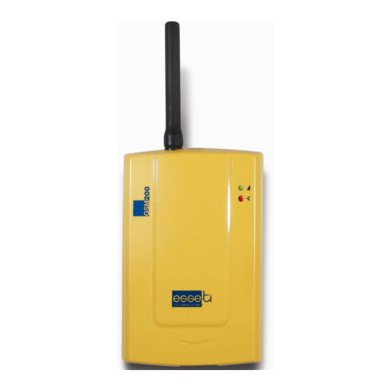
Page 7: Installation
INSTALLATION Remove the cover. ANTENNA connector LED indicating signal strength (green) and LED indicating device operation status (red) SIM CARD housing RJ45 for module connection to Esse-ti elevator alarm systems or GSM Combi board Pagina 7... -
Page 8: Inserting The Sim Card
Inserting the SIM card Before inserting or replacing the SIM card, always make sure that the module has been disconnected from the mains and that no electrostatic discharge is present in order to avoid damaging it. Take all necessary measures to avoid electrostatic discharge. Shift the SIM card housing cover upward and lift Carefully slide the SIM card in its housing cover. -
Page 9: Programming
PROGRAMMING When using the GSM200 module for connection with any Esse-ti alarm system, please make sure the parameter “Programming the type of telephone line” has been adequately set in the specific alarm system. Lift the local telephone handset of the elevator alarm system. -
Page 10: Connections
CONNECTIONS Helpy L300 / Helpy L300 TL Make sure that the jumpers JP11 and JP12 located on the Helpy L300/Helpy L300 TL are in position 2-3 (towards the RJ45 connector). Insert the provided cable (pin-to-pin cable) in to the two RJ45 connectors located on the Helpy L300/Helpy L300 TL and GSM200 module. -
Page 11: St56 / Helpy Star
In order to reach longer distances (up to 100m), please use a cat.5 or higher cable. ST56 / Helpy Star Make sure that, on the ST56/Helpy Star, jumpers are inserted in the larger connector for optional PSTN line board. Insert the provided cable (pin-to-pin cable) in to the two RJ45 connectors located on the ST56/Helpy Star and GSM200 module. -
Page 12: Starting
STARTING After the connection, make sure that the red LED (indicating the device operation status) located on the GSM200 module is switched on and stays lit for a few seconds before it starts blinking. In case the red LED should not be blinking, the GSM module would not be correctly registered to the GSM network provider. -
Page 13: Test Call
Test call Lift the local telephone handset of the elevator alarm system. Dial: < Installer password > (by default: (dialing tone) Dial: (dialing tone) Dial: (telephone number) Note: wait about 10 seconds after dialling the desired telephone number before confirmation tone indicates that the call has been forwarded. -
Page 14: Gsm200 Installation Recommendations
GSM200 installation recommendations • The module is provided with a 3m. cable. Use a cat.5 or higher cable to connect the GSM200 module at a longer distance (up to 100m). • The minimum recommended distance, between the GSM200 module and the elevator alarm system, is 50cm. -
Page 15: Signalling
SIGNALLING LED indicating device operation status (RED) Normal operation LED indicating GSM signal strength (GREEN) No signal Low signal level Medium signal level High signal level Pagina 15... - Page 16 GSM200 Rel. dated 15/12/2011...
Need help?
Do you have a question about the GSM 200 and is the answer not in the manual?
Questions and answers
Hi, how do I change the password on the helpy. *0# doesn't work. Thanka