
Related Manuals for Ace Sports Maxxam 150 2R


Summary of Contents for Ace Sports Maxxam 150 2R
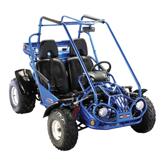
- Page 1 Buggy Service Manual 150 2R 239 County Road 4435 Brundidge, AL 36081 www.acesportsonline.com P: 1-888-562-9ACE F: 1-888-562-8ACE ACE-Maxxam-002-02-2007...
- Page 3 FOREWORD This service manual has been specially prepared to provide all the necessary information for the proper maintenance and repair of the MAXXAM . The MAXXAM ts the needs of a wide variety of kart users above 16 years old. Those who will be servicing this kart should carefully review this manual before performing any repair or services.
-
Page 4: Table Of Contents
GENERAL INFORMATION PERIODIC MAINTENANCE AND TUNE-UP PROCEDURES ENGINE LUBRICATION SYSTEM INSPECTION AND SERVICING FUEL SUPPLY SYSTEM INSPECTION AND SERVICING TRANSMISSION CONPONENTS ELECTRICAL STARTING SYSTEM REDUCTION MECHANISM CONTROLLING MECHANISM BELT DRIVEN CVT MECHANISM INSPECTION AND SERVICING CLUTCH DRIVEN BELT PULLEY REAR TRANSMISSION MECHANISM INSPECTION AND SERVICING ELECTRICAL SYSTEM PRIMARY COIL IGNITION SYSTEM INSPECTION AND SERVICING... -
Page 5: General Information
GENERAL INFORMATION MODEL IDENTIFICATION FRAME NUMBER The frame number or VIN is stamped under the seat on the frame cross member and on a sticker behind the seat. ENGINE NUMBER The engine number is located on the lower front left side of the engine case. FUEL AND OIL RECOMMENDATIONS FUEL Gasoline should be 85 to 95 octane or higher. -
Page 6: Specifications
SPECIFICATIONS DIMENSIONS Overall length 2075mm (87.7 in.) Overall width 1235mm (48.6 in.) Overall height 1400mm (55.1 in.) Wheelbase 1450mm (57 in.) Front Track 1060mm (47.1 in.) Rear Track 1000mm (39.4 in.) Ground Clearance 130mm (5.1 in.) ENGINE Type Forced air-cooled, 4-stroke Engine capacity 150cc Bore x stroke... - Page 7 68.95 68.95...
-
Page 8: Location Of Parts
LOCATION OF PARTS DRIVE CHAIN DRIVE CHAIN... -
Page 9: Periodic Maintenance And Tune-Up Procedures
PERIODIC MAINTENANCE AND TUNE-UP PROCEDURES PERIODIC CHECK AND SERVICES The maintenance intervals in the following table are based upon average riding conditions. Riding in unusually dusty areas requires more frequent servicing. Items Needing Initial Service Monthly Quarterly Yearly Servicing rst week) Tire pressure/wear Brake performance Tightness of screws... - Page 10 TIRE PRESSURE/WEAR Check the tire pressure every time the kart is ridden. The tire pressure is very important for the stability of the ride. Tire Pressure 10 psi 68.95kPa/cm Front 0.70kgf/cm 10 psi 68.95kPa/cm Rear 0.70kgf/cm BRAKE PERFORMANCE • Always check that there is plenty of brake uid in the brake uid reservoir. •...
- Page 11 CHASSIS NUTS AND BOLTS Note: Always pay attention to the kart's nuts and bolts. Some loosening after use is normal. Check to ensure that all nuts and bolts are tight. Torque Tightening Chart Bolt Conventional Marked Bolt 8.8 Marked Bolt Diameter Kg.m Ib-ft...
- Page 12 before gear Replace screen and drain plug.
-
Page 13: Engine
ENGINE ENGINE COMPONENTS INSPECTION AND SERVICING ENGINE COMPONENTS AND CRANK CONNECTING ROD MECHANISM INSPECTION AND SERVICING ENGINE COMPONENTS: CYLINDER CYLINDER REMOVAL The removal can be done on the vehicle body. • Remove cylinder head. • Remove cylinder. • Remove cylinder gasket, bolts •... - Page 17 CRANKSHAFT AND CRANKCASE INSPECTION • Replace the whole set of the crankshaft if serious wear is found while inspecting. Measure the axial trend clearance of the big end of the connecting rod. • When measuring, put the large end of the connecting rod close to the crank, and insert the feeler gauge between the other side and the crank, for the correct end play.
- Page 19 enable the engine to run properly, • • • •...
- Page 20 causes too much play,...
- Page 21 CAMSHAFT INSTALLATION • • • • ROCKER ARM AND ROCKSHAFT ROCKER ARM AND ROCKSHAFT REMOVAL • ROCKER ARM AND ROCKSHAFT INSPECTION...
- Page 22 • Measure the inner diameter of the rocker arm. Service Limit 10.04mm • Measure the outer diameter of the rockshaft. Service Limit 9.96mm ROCKER ARM AND ROCKSHAFT INSTALLATION Read the “ EX” mark on the camshaft holder, then mount the exhaust port rocker arm to the rock- shaft.
- Page 23 VALVE AND VALVE SPRING VALVE AND VALVE SPRING REMOVAL • Remove cylinder head. • Remove valve cotter pin and compressor. • Remove upper spring race. • Remove valve spring. • Remove lower spring race. • Remove valve stem oil seal. •...
-
Page 24: Valve Guide
VALVE GUIDE Carbon accumulation on the valve guide will make the valve move roughly, causing the valve to not open or close properly. Valve guide abrasion is one of the causes of white smoke from the exhaust pipe. TO CLEAN CARBON ACCUMULATION OFF THE VALVE GUIDE •... -
Page 25: Valve Seat
• After tapping the valve guide, you need to trim it with a reamer. When using the reamer, cutting oil must be used. The reamer can only be turned right; do not push in or out directly. • Clean the cylinder head, and remove the scraps generated while reaming. VALVE SEAT The relative position between the valve seat and the working surface of the valve is very important for the valve to seal properly. - Page 26 . Place...
- Page 27 ve. U ing area Follow the same method as for lace . Turn . If the lines are all broken, the level of air satisfactory...
-
Page 28: Lubrication System Inspection And Servicing
LUBRICATION SYSTEM INSPECTION AND SERVICING GENERAL INTRODUCTION The picture shows the functional diagram of the lubrication system. After the lubrication oil crosses it is pumped by the rotator oil pump Some of the oil goes into the big end of the connecting rod and splashes on the cylinder wall and the small end of the connecting rod;... - Page 29 allow . Replace if damaged. and tighten appropriate kage. Stop the engine and inspect for proper oil level. . Inspect and maintain it . If , replace it as a unit. , followed by removing...
- Page 30 followed by removing followed by After removing...
-
Page 32: Fuel Supply System Inspection And Servicing
• Mount the right crankcase cover positioning bolt. • Mount the trigger winding and the stator coil. • Tighten the right crankcase cover positioning bolt. The bolt should be gradually diagonally tightened in two to three steps. spect for any oil leaks. FUEL SUPPLY SYSTEM INSPECTION AND SERVICING CV CARBURETOR The CV carburetor is a constant vacuum carburetor. - Page 33 CARBURETOR IDLING ADJUSTMENT AIR ADJUSTING SCREW ADJUSTMENT Step one: T urn on the air adjusting screw in the turn out by the prescribed number of turns. Turn out number of turns 2 3/4 – 2 1/4 Step two: Adjust the throttle by adjusting the screw to the prescribed idle rpm. Step three: Left and right, adjust the air adjusting screw slightly to nd the highest position of the rpm.
- Page 34 Insert the spring vacuum...
- Page 35 Before removing rst tighten the two screws gently, counting the number of turns Remove screws. Do not use excessive force to avoid damaging the air adjusting screw head surface. • Remove the main fuel injection nozzle and fuel injection needle seat. FLOAT CHAMBER INSTALLATION oat valve seat for wear.
- Page 36 AIR CUT VALVE (ACV) The air cut valve can avoid some abnormalities when the throttle closes too quickly. The structure of the air cut valve is shown in the picture. AIR CUT VALVE REMOVAL • Remove the air inlet manifold of the cut valve. •...
- Page 37 TRANSMISSION COMPONENTS STARTING MECHANISM INSPECTION AND SERVICING The starting mechanism can be divided into two types: kick starting and electric starting. SPIRAL SPLINE TRANSFERRING STYLE STARTING MECHANISM The picture shows the structure of the spiral spline transferring style starting mechanism. 1.
-
Page 38: Electrical Starting System
ELECTRICAL STARTING SYSTEM STARTER MOTOR The starter motor is actually a direct current (DC) motor, and its structure is shown in the picture. 1. Outer Cover, Motor 7. O-ring 2. Rotor, Motor 8. O-ring 3. Base, Carbon Brush 9. Bolt 4. - Page 39 shavings the armature surface, on the immediate right far-...
- Page 40 STARTER MOTOR INSTALLATION • Apply some oil on the dust seal. • Install the carbon brush on the carbon brush base. • Apply a little oil on the moving part of the armature ends. • Put the carbon brush into the bracket, and then install the carbon brush base.
-
Page 41: Reduction Mechanism
REDUCTION MECHANISM The picture shows the structure of the reduction mechanism. 1. Starter reduction gear 12. Bolt 2. Starter reduction gear shaft 13. Nut 3. Starting clutch gear comp. 14. Washer 4. Starting clutch outer comp. 15. Dowel pin 5. Flange starting clutch 16. - Page 42 ENGAGING MECHANISM STARTING CLUTCH REMOVAL • Remove the right crankcase cover. • Remove the left crankcase cover. • Hold the drive face with the universal set wrench. • Remove the starting clutch xing nut. handed rotation. • Remove the starting clutch (the whole set). STARTING CLUTCH INSPECTION The driving gear should smoothly turn clockwise, and should not move counterclockwise.
- Page 43 While h If clicking sound is not heard, for conductivity the conductivity of the start button it is , then...
-
Page 44: Belt Driven Cvt Mechanism Inspection And Servicing
BELT DRIVEN CVT MECHANISM INSPECTION AND SERVICING Conversely, the speed decreases when the diameter of the driving belt pulley changes from big to small, and the diameter of the driven belt pulley changes proportionally from small to big. - Page 46 While holding remove the...
- Page 48 replace it and the...
-
Page 49: Clutch
• Remove the clutch friction plate. • Remove the whole clutch/driven plate set. • While compressing the driven pulley spring with the clutch spring compressor, remove the nut on the shaft. • Disassemble the clutch with the driven pulley. • Remove the circlip, and remove the connecting piece. •... - Page 50 for wear...
- Page 52 for cracking and wear...
- Page 53 for oil leakage Always refill with the specified oil...
-
Page 54: Driven Belt Pulley
• Supply the oil with the prescribed speci cation and oil level. • Mount the level bolt. • After replacing the oil, inspect for any oil leaks. TRANSMISSION CASE TRANSMISSION CASE REMOVAL • Remove the driven belt pulley. • Drain out the oil in the transmission case. •... -
Page 58: Electrical System
ELECTRICAL SYSTEM CHARGING SYSTEM INSPECTION AND SERVICING ELECTRIC LEAKAGE TESTING • Turn the main switch to the “OFF” position. • Disconnect the negative ground wire from the battery. • Connect the positive end of the ammeter with the negative end of the battery. •... - Page 59 BATTERY The battery is an important component of the electric system. The battery used on the vehicle is a maintenance-free battery. For long periods of storage, the battery will discharge. It should be charged every 3 months. After 2 ~3 years of regular usage, the capacity of the battery will lessen and will need changing.
-
Page 60: Primary Coil
BATTERY CHARGING • Lift the battery out of the vehicle. • Connect the positive pole of the charger with the positive pole of the battery. • Connect the negative pole of the charger with the negative pole of the battery. •... - Page 61 While h...
- Page 62 Perform...
- Page 63 . If...
-
Page 64: Ignition System Inspection And Servicing
IGNITION SYSTEM INSPECTION AND SERVICING The circuit working principle is shown in the picture. B-Black R-Red Main switch (ignition switch) Y-Yellow Bl-Blue W-White G-Green Ignition coil C.D.I Unit Ignition charging coil Capacitor Diode Spark plug BL/Y Silicon Controlled Trigger winding rectifier Primary coil Secondary coil IGNITION TIME INSPECTION... - Page 65 highest the problem the problem...
- Page 66 TRIGGER WINDING • Remove the connector of the trigger winding wire. • Measure the resistance value between the trigger winding (green/red wire) and the body ground wire. Standard Value When the actual value is more than the standard value, it should be replaced. CDI COMPONENT component inspection is also divided into two steps: First inspect every wiring,...
-
Page 67: Ignition Coil
IGNITION COIL IGNITION COIL REMOVAL • Remove the spark plug cap. • Remove the primary ignition coil wire. • Remove the ignition coil-positioning bolt, and remove the ignition coil. IGNITION COIL INSTALLATION • Reverse the removal procedure for installation. When installing, connect the black/yellow wire of the primary ignition coil with the black/yellow connector of CDI, and the green wire with the green connector of the CDI. -
Page 68: Chassis
CHASSIS... - Page 69 front...
- Page 70 bearings are dirty or muddy it goes seat. Fills teering gear...
- Page 71 THROTTLE & BRAKE PEDAL • Remove throttle, throttle pedal and axle nut, check for signs of wear. Replace if wear is present. • Fill with grease in order to make the throttle & brake pedal swing more flexibly before installation. A-ARMS •...
- Page 72 SERVICE AIR CLEANER Service pre-cleaner every 100 hours. NOTE: service more often under dusty conditions. • Remove cleaner cover. • Remove air cleaner. Element 2, 3. TO SERVICE PRE-CLEANER • Clean foam lter with non- ammable cleaner. • If lter is made of paper lter.
- Page 73 CHAIN TENSIONER ADJUSTMENT rst two hours of operation, check the chain adjustment, and readjust if is has more than Loosen Nut 1 Adjust Nut 2 (Turn nut clockwise in 1/2 turn increments, then turn nut#1 clockwise until nut is REVERSE GEAR CHECK , replace them if wear is pres-...
-
Page 74: Wiring Diagram
WIRING DIAGRAM... - Page 75 A-ARMS ADJUSTMENT OF FRONT & REAR SHOCK AIR ADJUSTING SCREW ADJUSTMENT AIR CHECK VALVE AIR CHECK VALVE INSTALLATION AIR CLEANER AIR CUT VALVE INSTALLATION AIR CUT VALVE REMOVAL AIR CUT VALVE(ACV) ARMATURE INSPECTION AUTOMATIC SIDE STARTER INSPECTION AUTOMATIC SIDE STARTER(CHOKE) BATTERY BATTERY CHARGING BATTERY INSTALLATION...
- Page 76 CLUTCH DISASSEMBLING CLUTCH INSPECTION CLUTCH INSTALLATION CLUTCH REMOVAL CONNECTING ROD END INSPECTION CONTROLLING MECHANISM CRANK CONNECTION ROD MECHANISM:PISTON SET CRANK CONNECTION ROD SET CRANKCASE AND CRANKSHAFT REMOVAL CRANKSHAFT AND CRANKCASE INSPECTION CRANKSHAFT AND CRANKCASE INSTALLATION CV CARBURETOR CYLINDER INNER WALL WEAR INSPECTION CYLINDER REMOVAL DIMENSIONS DRIVE BELT PULLEY...
- Page 77 REDUCTION MECHANISM REGULATE RECTIFIER REGULATE RECTIFIER INSPECTION REMOVE THE CDI COMPONENT RESISTOR RESISTOR RESISTANCE VALUE MEASUREMENT REVERSE ADJUSTMENT REVERSE GEAR CHECK ROCKER ARM AND ROCKSHAFT ROCKER ARM AND ROCKSHAFT INSPECTION ROCKER ARM AND ROCKSHAFT INSTALLATION ROCKER ARM AND ROCKSHAFT REMOVAL ROTARY OIL PUMP SEAT SECONDARY IGNITION COIL INSPECTION...
- Page 78 FUEL AND OIL RECOMMENDATIONS FUEL LEVEL INSPECTION FUEL SUPPLY SYSTEM INSPECTION AND SERVICING FUEL SWITCH (PETCOCK) GEARING ON THE TRANSMISSIION CASE COVER REPLACEEMENT GENERAL INFORMATION GENERAL INTRODUCTION GENERAL INTRODUCTION GENERAL INTRODUCTION GENERATOR INSTALLATION GENERATOR REMOVAL GENERATOR REMOVAL AND INSPECTION IGNITION CHARGING COIL IGNITION COIL IGNITION COIL INSTALLATION IGNITION COIL REMOVAL...
- Page 79 TRANSMISSION CASE OIL REPLACEMENT TRANSMISSION CASE REMOVAL TRANSMISSION CONPONENTS TRANSMISSSION CASE OIL REPLACEMENT TRIGGER WINDING VACUUM CHAMBER VACUUM CHAMBER INSTALLATION VACUUM CHAMBER REMOVAL VALVE AND VALVE SEAT AIR IMPERMEABILITY INSPECTION VALVE AND VALVE SEAT LAPPING VALVE AND VALVE SPRING VALVE AND VALVE SPRING INSPECTION VALVE AND VALVE SPRING INSTALLATION VALVE AND VALVE SPRING REMOVAL VALVE CLEARANCE...
Need help?
Do you have a question about the Maxxam 150 2R and is the answer not in the manual?
Questions and answers