Advertisement
Quick Links
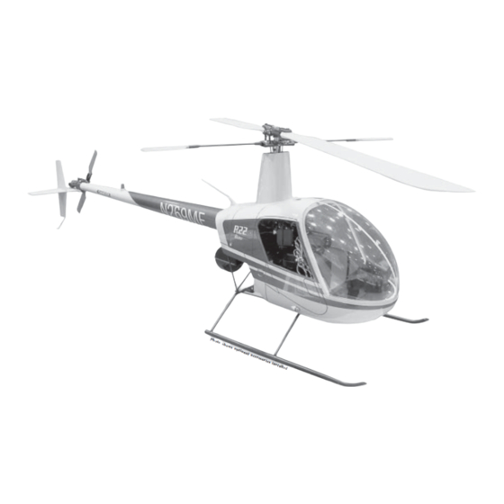
Robinson 22HP
Helicopter
GELCOAT FIBERGLASS FINISH
CRYSTAL CLEAR WINDSHIELD
SCALE WIRE LANDING GEAR
SCALE ELEVATED TAIL BOOM
ENGINE SIZE
MAIN ROTOR DIAMETER
HEIGHT
LENGTH
Century Helicopter Products
Designed and Developed in USA
Instruction Manual
FEATURES
1st Edition June, 2003 All rights reserved.
.50
58"
19"
47"
Advertisement

Related Manuals for Century Helicopter Products Robinson22HP


Summary of Contents for Century Helicopter Products Robinson22HP
-
Page 1: Instruction Manual
FEATURES GELCOAT FIBERGLASS FINISH CRYSTAL CLEAR WINDSHIELD SCALE WIRE LANDING GEAR SCALE ELEVATED TAIL BOOM ENGINE SIZE MAIN ROTOR DIAMETER 58” HEIGHT 19” LENGTH 47” Century Helicopter Products Designed and Developed in USA 1st Edition June, 2003 All rights reserved. -
Page 2: Pre-Assembly Information
Care has been taken in filling and packing of each bag. However mistakes do happen, if there is a parts shortage or any hardware missing, please feel free to contact us at: Century Helicopter Products 523 Sinclair Frontage Road Milpitas, CA 95035 USA Fax: 408-942-9524 www.centuryheli.com... -
Page 3: Recommended Tools & Accessories
Robinson 22HP Construction Manual This manual has been written for Century’s 50 size Robinson 22HP scale helicopter. This manual should be reviewed before starting the assembly as there are a few complicated sections to attach the various fiberglass components to the mechanics. Instructional Detail Every attempt has been made to ease the assembly of your helicopter, at each step where there are complex assemblies, there are detailed drawings, photos and written instructions to walk you... - Page 4 #HI3181 Damper Step 1 Rotor Head Block Rubber x 2 Press in the Damper Rubbers Head Block. Apply Triflow oil or similar teflon oil to the inside of the dampers. Dampers should be replaced on a yearly basis. Step 2 Seesaw Assembly Insert one ball bearing into each bearing cup and insert into the offset #CN1076-13...
- Page 5 Step 3 Main Rotor Grip Assembly #HI3184 Robinison 22HP Manual Main Rotor Blade Insert the slide tube into the bell mixer arm Grip x 2 from the offset side, through the oilite bearings (installed already) and secure onto the blade grip with one M3x16 Socket Cap screw and M3x7 Flat washer.
- Page 6 #HI3176C Step 5 Flybar Control Yoke Assembly Flybar Control Arm x 2 Double Studded Ball x 2 Using an available M3x12 Button Head Screw, Tapered Standoff x 2 insert approximately half the length of the screw to form threads into the smaller, tapered ends of the control arms and the control arm stand-offs.
- Page 7 Step 7 Washout Assembly Robinison 22HP Manual Attach two Medium Balls (Tip 2) to the Washout Mixing Arms ( note they are attached from the flat side of the arm). Using one slide tube inserted from the flat side, secured using one M3x16 Button Head Screw and one 3x7mm Flat Washer per arm.
- Page 8 Step 9 Starting Shaft Bearing Blocks M5x10 Collar The Start Shaft Guide M2x5 Self Blocks are pre- Spring Tapping Screw assembled. Slide the M5x10 Starter Shaft through M2x5 Flat Flat one of the block Washer Washer assemblies with the M5x11 Ball Bearing facing up then slide the #CNBB1150 M5 Flat Washer, spring...
- Page 9 Step 11 Counter Gear Assembly Robinison 22HP Manual Assemble the engine counter gear assembly, start by pressing the guide pin into the hole in the end of the Drive Shaft. Insert the shaft through the Counter Gear ( make sure the pin is fully seated in the recessed side of the gear ) then slide the two M5x13 Ball Bearings.
- Page 10 STEP 12 Main Gear & Shaft Assembly The Main Gear is pre-assembled with the Auto- Rotation Bearing installed. Insert the bottom end of the main shaft through the auto rotation gear assem- bly, align the holes and secure the Main Shaft using one M3x16 Socket Cap Screw and one M3 Lock- nut.
- Page 11 Step 14 Upper Side Frames Robinison 22HP Manual Install two 4x4mm Set Screws (do not apply locktight at this time) in the Mast Stopper (note the raised inner diameter must face the ball bearing) and slide the mast stopper on the main shaft followed by one M10x19 Ball Bearing and one M14x19 Spacer (the spacer must be installed on top of the bearing).
- Page 12 Step 15 Upper Frame Assembly & Front CCPM Servo Mounts Insert two long hex spacers at the specified locations in the diagram, note that the front hex spacer is installed into the forward-most hole. Attach the left side CCPM Servo Mount using four M3x12 Self Tapping Screws (Tip3) into the starting shaft blocks.
- Page 13 Step 17 Front CCPM Servo Mounts Robinison 22HP Manual Install both CCPM front servos at this time, with the output shaft of #HI3205 the servos positioned upwards and the servo flange inserted from Servo behind the servo mount. Using the screws provided, insert the mount tabs screws from the servo top through the grommets (insert the eyelets between the grommet and the mount bracket) and...
- Page 14 Step 20 Clutch, Fan & Engine Mounting Remove all parts from the engine Engine Thrust Washer crankshaft until you can see the front or M9x14 FW ball bearing, install the 9x14mm Flat washer (or washer provided by Engine ball M5x13 Flat bearing engine manufacturer), insert the Ball Washer...
- Page 15 Step 22 Fuel Tank Assembly Robinison 22HP Manual Insert the two pieces of aluminum tubing through the large cap, rubber stopper and small cap, bend the long alumi- num tube upwards and attach the short piece of fuel line and clunk to the short straight piece of tubing. Test fit the assembly into the Fuel Tank and make sure that the clunk reaches the end but moves freely and the vent tube is near the top of the tank but does not touch.
- Page 16 Step 24 Tail Output Shaft Assembly Notice that the tail rotor output drive #HW3073 shaft has 2 holes, one through the Tail Rotor Drive shaft and one drilled partially into the Shaft shaft. Slide the small bevel gear (A) #HI3075 #HW3074 with the teeth facing the shaft from Small Bevel...
- Page 17 Step 27 Tail Gearbox Assembly Robinison 22HP Manual Tail Pitch Plate Assembly Slide two Ball Bearings on each side of the tail rotor output shaft assembly and insert through the right side of the Tail Rotor Gearbox #CNBB1150 Housing, make sure the 5x11 Ball bearing is fully seated into the Bearing x 2...
- Page 18 Step 29 Tail Blade Assembly M3 Locknut x 2 Snap the ball on the tail rotor grip into the adjoining pitch slider link on both sides. Install the tail rotor blades shimmed with M3x10 plastic washers on both sides using two M3x20 socket cap screws and M3 locknuts.
- Page 19 Robinison 22HP Manual Step 32 Tail Gearbox Assembly Attach the tail input gear assembly on to the drive shaft with two M4x4 set screws (Tip 1 - make sure the flat spot is aligned with one of the set screws and only use ONLY blue locktite here) apply red locktite to the drive shaft end and insert into the gearbox input shaft.
- Page 20 Step 33 CCPM Radio Review & Setup The next section covers setting the pushrods and servos that will control the helicopter. It is important at this time that you review the instructions provided with your radio that controls the ccpm mixing for the 3 cyclic servos. Reviewing the radio instructions will assist you in becoming familiar with the functions that affect the individual servos and affect the interaction of the three servos working together to control the swashplate.
- Page 21 Step 35 Pushrod Setup and Adjustments Robinison 22HP Manual Make up all the control pushrods according to the specified lengths shown in the table. Please note that the dimensions listed are from center to center of the ball ends (this has changed from earlier manuals). Depending on the servo brand, the servo horn offers different patterns for fine tuning.
- Page 22 Step 36 Rotorhead Pushrod Attachment After completing the pushrods, attach the pushrods to the rotor head without the cabin or shroud installed on the helicopter mechanics. At this point the helicopter should be setup, ready to fly, except for the tail rotor and throttle linkages before the fiberglass cabin and tail boom are installed.
- Page 23 Servo Setup & Adjustments Robinison 22HP Manual Over the next few pages the pushrod hardware will be mounted to the servos horns and ultimately the pushrods them- selves. Each step is well described but lets take a few moments to cover a few basic points on setting up individual servos.
- Page 24 Step 37 CCPM Swashplate Linkage Three servos are mounted on the front and rear servo brackets. They work together to tilt the swashplate producing the collective pitch, roll cyclic pitch (aileron control) and the fore-aft cyclic pitch (elevator control). The servo horns pro- vided in the radio will not be long enough to achieve the full collective range, the control ball is required to be mounted at a distance of 25-26mm from the center of the servo.
- Page 25 Step 38 Rudder Linkage Robinison 22HP Manual The Rudder linkage changes the pitch of the tail rotor blades to increase or decrease the torque compensation to rotate the nose of the helicopter about the main shaft. Use a servo horn in the shape of a cross and find the correct arm that will sit at 90 degrees to the length of the servo by lightly pressing the servo horn over the output shaft on the servo.
- Page 26 Step 39 Throttle Linkage Attach the throttle mount to the left side of the front mechanics with the knotch towards the starting shaft using two M3x10 socket cap screws in the front, threaded into one M3x30 hex spacer and one M3x8 socket cap screw and M3 locknut on the inside of the frames.
- Page 27 Step 40 Muffler Attachment Robinison 22HP Manual With the narrow space between the mechanics and the fuselage, it is recommended to install the scale muffler Century has designed for scale fuselages. Attach the muffler to the engine with the screws provided with the muffler (Tip 1- using hi-temp Optional threadlock).
- Page 28 STEP 42 Tail Pushrod Guide Positioning Insert three rudder pushrod guides positioned 7 3/4”, 14” and 21” from the front of the tail boom. Do not bond them at this time until the tail boom has been test fitted with the fiberglass tail boom. Connect the long rudder pushrod to the pushrod coupler and attach the 104mm pushrod.
- Page 29 Robinison 22HP Manual Step 44 Preparing and painting the kit version. This section is written to cover painting and detailing of fiberglass components using in Century’s scale helicopter kits. Some included references may describe components of different kits, not exclusive to this instruction manual. Flexibility A wonderful attribute of fiberglass is in its flexibility.
- Page 30 3. Once the detail parts have been built into the sub assemblies are ready to paint, use a filler in sections that have gaps or slight surface imperfections, occasionally there are voids (air bubbles in the resin) that occur near the surface that need to be filled.
- Page 31 R22 Fiberglass Components Robinison 22HP Manual At this point, the flying mechanics should be assembled flight ready and possibly flight tested. The remaining items to be checked before proceding is the collective pitch setup and double check the servo throws for any binding. Now is the time to finalize the setup because access to the rotorhead is very restricted after the complete cabin and top shroud are assembled.
- Page 32 STEP 47 Cutout Window & Navigation Lights #CN1076-2 Top window & Mark a line 3/16”[4mm] outside the molded line and Nav lights cut out the parts from the plastic sheet. Carefully continue to trim the parts as you test fit them to their final positions.
- Page 33 Robinison 22HP Manual STEP 51 Cutout Window & Navigation Lights #CN1076-2 Navigation Lights Taking the navigation lights, continue trimming as they are fitted to the front of molded lights on the main cabin. Once trimmed, paint the navigation lights from the inside to preserve the high gloss outside surface.
- Page 34 STEP 54 Front Landing Gear Mounts Slide one M3x9 plastic spacer onto the front landing gear stud followed by one M3x7 flat washer (additional washers may be necessary to lift the engine head from touching the landing gear), then the main mechanics and one M3 locknut and leave loose for now.
- Page 35 STEP 57 Top Shroud Installation Robinison 22HP Manual Before the cabin can be installed the top shroud needs to be fitted. Remove the rotor head assembly and insert through the finished fiberglass shroud. Ensure that the washout arm pushrods are connected to the “A” pushrods and that the longer “C”...
- Page 36 STEP 59 Receiver & Rx Battery Mounting #CN1076A Scale Accessory Kit (not included) The receiver and the receiver battery pack should be mounted in the bottom of cabin all the way in the front to balance the helicopter. Underneath the scale instru- ment panel (if purchased separately.
- Page 37 STEP 61 Tail Gearbox Assembly Robinison 22HP Manual Position the output gear assembly into the right gear box half (insure the 2 bevel gears are meshed properly and the ball bearings are fully seated in their recesses) and liberally greased the gears before closing the gear box. Position the gear box halves over the holes in the end of the tail boom and secure with one M3x10 Socket Screw and M3 Locknut at the end of the gear box and one M3x16 Socket Screw and M3 Locknut at the center-top location.
- Page 38 STEP 63 Scale Engine Exhaust CN1076A Scale Foam Tape Accessory Kit (not included) (Optional Scale Accessory Kit) Here If the optional accessory kit has been purchased the scale engine exhaust needs to be fitted before the cabin can be installed on the mechanics. Start by attaching the spring to the top surface of the engine exhaust.
- Page 39 STEP 66 Attaching the Tail Boom Assembly Robinison 22HP Manual Once the foam insert is modified in the last step it can be positioned inside the fiberglass tail boom. Simply press the insert into the tail boom until it stops. The rudder pushrod is inserted into the smaller hole to the right of the central cutout.
- Page 40 Final Adjustments - Radio Setup Now that the servo installation into the helicopter is finished the following pages should be reviewed. As various types of radios can be used to setup the helicopter, some of the following information may not apply.
- Page 41 Before Flying your Helicopter Robinison 22HP Manual Before each flight, check that all bolts and screws are tight. Simply flying your helicopter, will loosen any screws which are not threadlocked or secured with a lock nut. First Flights For the beginner pilot, a training pod is strongly recommended to assist in learining to hover the helicopter with substantially reduced risk of crashing.
- Page 42 Note 2: The tail rotor is mounted on the left side of the Tail Rotor Setup (rate gyro) helicopter, this is opposite to all our regular models. What separates airplane radio equipment from the helicopter version is in the control of the individual For each flight mode setting, there will be different curves discussed earlier and in the Revo-mixing Revo-mixing amounts.
-
Page 43: Pre-Flight Checklist
Basic Hovering Robinison 22HP Manual When all is set, ready and checked, attach your training gear/pod and start the engine. (1) Place the helicopter pointing into the wind and stand behind the model about 15' away. (2) Always watch the nose of the helicopter, move the rudder left and the nose will move left. (3) Start by increasing the throttle slowly until the helicopter rises 2-6 inches off the ground then set it back down. - Page 44 Robinson 22HP Replacement Parts HW3000 Hardware Pack CN0402 Hex Start Adapter w/set screw(5mm) CNLR1000S Ball Links 2mm (Grey) - Tail Pushrod HW3005A Hardened Start Shaft Assembly CNLR1003 Micro Washer 3x5x0.5T HI3007 Starter Shaft Bearing Blocks HI3009 Cooling Fan CNLR1013 Black M2 Steel Ball - Short (servos) HI3010A Machined Clutch Bell &...
Need help?
Do you have a question about the Robinson22HP and is the answer not in the manual?
Questions and answers