Table of Contents
Advertisement
Quick Links
Advertisement
Table of Contents

Related Manuals for E-FLITE F-4 Phantom 32 DF


Summary of Contents for E-FLITE F-4 Phantom 32 DF
- Page 1 Инструкция E-Flite F-4 Phantom 32 DF Перейти в карточку товара 8 800 775 98 98...
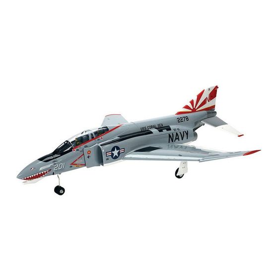
- Page 2 F-4 Phantom 32 DF Assembly Manual * Pilot figures shown are not included...
-
Page 3: Meaning Of Special Language
Fly only in open areas to ensure safety. It is Safety can never be taken lightly. recommended flying be done at AMA (Academy of Model Aeronautics) approved flying sites. Consult local laws and ordinances before choosing a location to fly your aircraft. E-flite F-4 Phantom 32 DF Assembly Manual... -
Page 4: Table Of Contents
) indicate the step will require repeating, such as Motor Setup ............4 an E-flite 6S 5000mAh 30C Li-Po pack. And it does for a right or left wing panel, two servos, etc. Optional Accessories ..........4 so without resorting to drag-inducing cheater holes. -
Page 5: Recommended Radio Equipment
PAAPT08 Light Gray HANU882 Threadlock PAAPT42 True Red HANU866 Silicone adhesive DEVS250 Silver HANU881 White HANU870 Hardware/Accessory Sizes Main wheel diameter -inch (48mm) Nose wheel diameter -inch (33mm) Wing bolt 8-32 x 1/4-inch E-flite F-4 Phantom 32 DF Assembly Manual... -
Page 6: Wing Tip Installation
This will keep the servos from moving to their endpoints until the transmitter and receiver connect. 6. Repeat steps 1 through 5 to install the remaining wing tip panel to the main wing panel. E-flite F-4 Phantom 32 DF Assembly Manual... -
Page 7: Hinging The Ailerons And Flaps
The gap between each surface, and the line projected from the wing root, should be equal. E-flite F-4 Phantom 32 DF Assembly Manual... -
Page 8: Aileron And Flap Servo Installation
Note that one servo is set in the opposite orientation as shown in the photo in the following column. E-flite F-4 Phantom 32 DF Assembly Manual... - Page 9 6. Position the servo between the two blocks. With the servo resting against the servo cover, use a pencil to mark the locations for the four servo mounting screws on the blocks. E-flite F-4 Phantom 32 DF Assembly Manual...
- Page 10 This is dependant on the exact location of the servo. Use the screws provided with the servo and a #1 Phillips screwdriver to attach the servo to the mounting blocks. E-flite F-4 Phantom 32 DF Assembly Manual...
-
Page 11: Control Horn Installation
3. Apply low-tack tape around the opening for the aileron control horn. Position the tape so it is 1/32-inch (1mm) away from the sides of the hole, as well as from the marks made in the previous step. E-flite F-4 Phantom 32 DF Assembly Manual... -
Page 12: Flap And Aileron Linkage Installation
Assemble the flap linkage using the silicone tubing, one 2mm nut, two metal clevises, and a 2mm x 25mm threaded rod. Use the length in the photo as a starting point for the length of the rod. E-flite F-4 Phantom 32 DF Assembly Manual... - Page 13 2 to the opposite flap until you have checked the throws. Doing so may cause the servo to bind in the UP position, which could cause damage to the flap servo. E-flite F-4 Phantom 32 DF Assembly Manual...
-
Page 14: Wing Spar Installation
The spar will slide in easily, so doesn’t get damaged. don’t force it in any further than it will slide. Use a felt-tipped pen to mark the spar at the wing root. E-flite F-4 Phantom 32 DF Assembly Manual... - Page 15 9/64-inch ball driver to lightly tighten the screws to secure the wing joiner in the fuselage, and low-tack tape to hold the wing in position until the epoxy has cured. E-flite F-4 Phantom 32 DF Assembly Manual...
-
Page 16: Main Landing Gear Installation
Leave 1/32-inch (1mm) of covering around the inside edges. Use a trim seal tool to iron down the covering around the edges to finish the opening. E-flite F-4 Phantom 32 DF Assembly Manual... - Page 17 Remove the screws after threading the holes. 4. Use the drill and drill bit prepared in the previous step to drill the four holes for the landing gear block or retract mechanism mounting screws. E-flite F-4 Phantom 32 DF Assembly Manual...
- Page 18 These struts are designed for the weight and speeds of the F-4 Phantom. Use the struts supplied with the kit for the retract assembly. E-flite F-4 Phantom 32 DF Assembly Manual...
-
Page 19: Optional Main Landing Gear Doors
If the wheel is hard to install, use a file to remove this bur. 10. Repeat steps 2 through 9 to install the remaining main landing gear and wheel. E-flite F-4 Phantom 32 DF Assembly Manual... - Page 20 Prepare both blocks at this time. 7. Use a drill and 1/16-inch (1.5mm) drill bit to drill the two mounting holes in the landing gear door block. E-flite F-4 Phantom 32 DF Assembly Manual...
- Page 21 Work slowly when using a sanding drum on the screws. The screws will heat up while sanding, which could melt the landing gear door. E-flite F-4 Phantom 32 DF Assembly Manual...
-
Page 22: Rudder And Elevator Servo Installation
16. Repeat steps 2 through 15 to install the second landing gear door. 3. Prepare and epoxy the servo mounting blocks as shown in the section “Aileron and Flap Servo Installation.” Allow the epoxy to fully cure before proceeding. E-flite F-4 Phantom 32 DF Assembly Manual... -
Page 23: Rudder Installation
Dipping the hinge knuckles in heated petroleum jelly (in a liquid state) is easier than trying to apply it with a toothpick in the gel state. E-flite F-4 Phantom 32 DF Assembly Manual... - Page 24 10. Attach the clevis to the torque rod. Slide the silicone tubing over the clevis. E-flite F-4 Phantom 32 DF Assembly Manual...
-
Page 25: Elevator Installation
Attach the clevis to the servo horn on the inner hole and adjust the length of the pushrod so the rudder is centered. Tighten the 2mm nut against the clevis, then slide the silicone tubing over the clevis. E-flite F-4 Phantom 32 DF Assembly Manual... - Page 26 Allow the CA to wick in between the two for a secure bond. 8. Once the elevator position has been set, slide the silicone keepers onto both clevises to keep the clevises from opening accidentally. E-flite F-4 Phantom 32 DF Assembly Manual...
-
Page 27: Fan Installation
10. Use the tape included with the model to attach Fan bottom the tail cone to the fuselage. 2. Follow the instructions included with the fan unit to prepare it for installation in your model. E-flite F-4 Phantom 32 DF Assembly Manual... - Page 28 This hardens the wood, making the screws fairing as well. more secure. You can also mount the pin vise in a drill so it can reach down inside the fuselage, saving some time when drilling the holes. E-flite F-4 Phantom 32 DF Assembly Manual...
-
Page 29: Nose Gear Installation
Flat file Phillips screwdriver: #1 The installation of the retracts and fixed gear follow the same procedure. The only difference is the installation of the nose gear strut, which has been highlighted in gray. E-flite F-4 Phantom 32 DF Assembly Manual... - Page 30 9. Install the steering servo in from the top of the fuselage using the hardware provided with the servo and a #1 Phillips screwdriver. The servo output faces the rear of the fuselage. E-flite F-4 Phantom 32 DF Assembly Manual...
- Page 31 12. Connect the clevis without the tubing to the steering arm of the nose gear assembly. E-flite F-4 Phantom 32 DF Assembly Manual...
- Page 32 2.5mm hex wrench. The 3mm screw can then be placed in the tubing and against the hex wrench so it can be easily installed to secure the landing gear. E-flite F-4 Phantom 32 DF Assembly Manual...
-
Page 33: Receiver And Speed Control Installation
Gear Flaps (requires Y-harness) Aux 1 Left Aileron Aux 2 Nose Gear Steering Aux 3 Retracts Programs for the F-4 Phantom using the DX8 are available for download on the Spektum website. E-flite F-4 Phantom 32 DF Assembly Manual... -
Page 34: Motor Battery Installation
Secure the leads inside the fuselage using clear tape. 2. Apply the mating hook and loop tape to the battery tray in the fuselage. E-flite F-4 Phantom 32 DF Assembly Manual... -
Page 35: Canopy Assembly
4. Place the interior in the canopy. It may be necessary to bend the interior slightly to fit past the canopy frame. 2. Use hobby scissors to trim the height of the pilots so they are 1 -inches (31mm) in height. E-flite F-4 Phantom 32 DF Assembly Manual... -
Page 36: Decal Placement
Apply the decals to your model using the photos located in this section of the manual, the box art from your model and on Page 43. E-flite F-4 Phantom 32 DF Assembly Manual... -
Page 37: Center Of Gravity
(145 to 155mm) back from the leading edge of the wing at the root as shown with the battery pack installed. Mark the location of the CG on the top of the wing with a felt-tipped pen. E-flite F-4 Phantom 32 DF Assembly Manual... -
Page 38: Control Throws
You can experiment with higher rates to Down match your preferred style of flying. High Expo 10% Expo 8% Expo 5% E-flite F-4 Phantom 32 DF Assembly Manual... -
Page 39: Range Test Your Radio
Generally, very slight back pressure on the elevator will allow the airplane to rotate smoothly at a comfortable, safe airspeed. The F-4 Phantom 32 will climb out at a nice angle of attack. E-flite F-4 Phantom 32 DF Assembly Manual... -
Page 40: Daily Flight Checks
HORIZON MAKES NO OTHER WARRANTY OR the nose. We hope you enjoy flying the E-flite F-4 REPRESENTATION, AND HEREBY DISCLAIMS ANY Phantom 32 4. Perform a ground range check before each AND ALL IMPLIED WARRANTIES, INCLUDING, day’s flying session. -
Page 41: Warranty Services
Champaign, Illinois 61822 USA Notice: Do not ship LiPo batteries to Horizon. If you productsupport@horizonhobby.com have any issue with a LiPo battery, please contact 877-504-0233 the appropriate Horizon Product Support office. E-flite F-4 Phantom 32 DF Assembly Manual... -
Page 42: Compliance Information For The European Union
AMA Document #555. (h) Not operate model aircraft while under the influence of alcohol or while using any drug which could adversely affect the pilot’s ability to safely control the model. E-flite F-4 Phantom 32 DF Assembly Manual... - Page 43 (b) Fly using the assistance of a camera or First-Person will be completed before the first flight of a new or View (FPV) only in accordance with the procedures repaired model aircraft. outlined in AMA Document #550. E-flite F-4 Phantom 32 DF Assembly Manual...
- Page 45 © 2011 Horizon Hobby, Inc. horizonhobby.com www.e-fliterc.com E-flite, Delta-V, DSM2, DSMX, Celectra, UltraCote, JR and the Horizon Hobby logo are trademarks or registered trademarks of Horizon Hobby, Inc. The Spektrum trademark is used with permission of Bachmann Industries, Inc. All other trademarks, service marks and logos are the property of their respective owners.
- Page 46 E-Flite F-4 Phantom 32 DF Описание...
Need help?
Do you have a question about the F-4 Phantom 32 DF and is the answer not in the manual?
Questions and answers