
Related Manuals for Hitachi HAMMER H 65SC


Summary of Contents for Hitachi HAMMER H 65SC
- Page 1 MODEL H 65SC POWER TOOLS TECHNICAL DATA HAMMER H 65SC SERVICE MANUAL LIST No. E451 Nov. 1999 SPECIFICATIONS AND PARTS ARE SUBJECT TO CHANGE FOR IMPROVEMENT...
- Page 2 REMARK: Throughout this TECHNICAL DATA AND SERVICE MANUAL, a symbol(s) is(are) used in the place of company name(s) and model name(s) of our competitor(s). The symbol(s) utilized here is(are) as follows: Competitors Symbols Utilized Model Name Company Name HM1303 MAKITA HM1500 MAKITA...
-
Page 3: Table Of Contents
Notice for use Specifications and parts are subject to change for improvement. Refer to Hitachi Power Tool Technical News for further information. CONTENTS [ Business Section ] Page 1. PRODUCT NAME • • • • • • • • • • • • • • • • • • • • • • • • • • • • • • • • • • • • • • • • • • • • • • • • • • • • • • • • • • • • • • • • • • • • • • • • • • • • • • • • • • • • • • • • • • • • • • • • • • • • • • • • • • • • • • • • • • • • • • • •... -
Page 4: Product Name
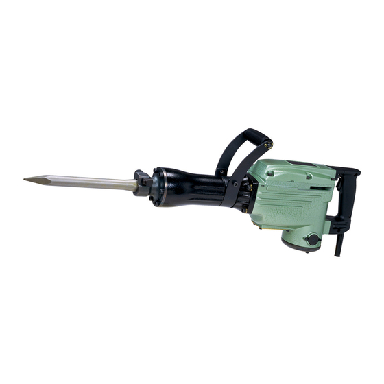
1. PRODUCT NAME Hitachi Electric Hammer, Model H 65SC 2. MARKETING OBJECTIVE The Model H 65SC is a double-insulated version of the existing single-insulated Model PH-65A. It has a recirculating lubricating system. Demolishing and chipping power is comparable to that of the PH-65A, as is the basic structure. -
Page 5: Selling Point Descriptions
Demolition performance is 1.1 to 1.3 times larger than that of similar products thanks to the maximum 39.5 J impact energy and efficient striking. Maker Model Ratio of demolished weight (%) • HITACHI H 65SC HITACHI PH-65A --- 2 ---... -
Page 6: Specifications
5. SPECIFICATIONS Item H 65SC Power source Single-phase AC 50/60 Hz Voltage (V) 110, 115, 230, 240 Motor type AC single-phase series commutator motor Insulation structure Double insulation Enclosure Materials: Aluminum alloy die casting Cast aluminum alloy Glass-fiber reinforced plastic resin Paint: Hammer-net silver green and black Switch... -
Page 7: Optional Accessories
5-1. Optional Accessories 1. Demolition work (1) Bull point Overall length Code No. 410 mm (16-9/64") 944961 2. Grooving and chiseling work (1) Cold chisel Overall length Code No. 410 mm (16-9/64") 944962 3. Cutting and stripping work (asphalt cutting, etc.) (1) Cutter Width Overall length... - Page 8 5. Tamping work (1) Rammer (2) Shank (SDS-max shank type) Overall length Code No. Code No. 944965 250 mm (9-27/32") 944966 Ext. Dia. 200 mm dia. (7-7/8") 6. Electric hammer oil Capacity Code No. 1 liter (0.26 gallon) 955009 (Note) Code numbers listed above are subject to change.
-
Page 9: Comparisons With Similar Products
6. COMPARISONS WITH SIMILAR PRODUCTS 6-1. Specification Comparisons Maker HITACHI Model name H 65SC PH-65A Power input 1,240 1,240 1,300 1,430 Full-load impact rate /min 1,400 1,400 1,450 1,300 Length (25-15/32") (25-9/32") (26-37/64") (25-15/32") Dimensions Height (9-1/4") (9-3/32") (8-11/32") (8-15/32") Width (4-23/32") -
Page 10: Precautions In Sales Promotion
Each Model H 65SC unit is provided with a Caution Plate (illustrated below) which lists basic safety precautions in its use. Carefully ensure that the customer fully understands and follows these precautions before using the tool. For the U.S.A. and Canada Hitachi Koki -- WARNING -- To reduce the risk of injury, user must read and understand instruction manual. -
Page 11: Impact Performance At Low Temperatures
Shell Omala Oil #150 without fail. To ensure that the appropriate oil is used, the customers should be urged to purchase and use the optional accessory Hitachi Electric Hammer Oil, Code No. 955009, which is available in one liter (0.26 gallon) containers. -
Page 12: Reference Information
8. REFERENCE INFORMATION 8-1. Structure of the Main Body The primary structure of the Model H 65SC is similar with the Model PH-65A, as illustrated. (Fig. 3) Gear Cover Ass'y Front Cover Inner Cover Striker Stop Lever Shank Sleeve L Ring Crank Shaft Counter Gear Switch Handle... -
Page 13: Movement Of The Stop Lever
8-3. Movement of the Stop Lever After an extended period of use, the operation of the Stop Lever may become difficult due to incursion of concrete powder or similar materials into its sliding portion. In such a case, apply oil into the sliding portion between the Stop Lever and fitting portion of the Front Cover. - Page 14 Press the end surface of the armature with a hand press. Inner Cover [45] Crank Shaft [37] Armature Ass'y [61] Tubular jig Fig. 6 Disassembly of the Crank Shaft [37] section First, remove the four Seal Lock Hex. Socket Hd. Bolts M5 x 16 [33] which fix the Bearing Cover [32]. Then, as illustrated in Fig.
- Page 15 Removal of the Striker [8] and related parts Remove the four Nylock Hex. Socket Hd. Bolts M8 x O-Ring [14] 35 [22], and separate the Cylinder Case [20] from the Slender screwdriver Housing Ass'y [59]. From the Cylinder Case [20], Shank Sleeve [15] take out the Striker [8], Piston [11], and Connecting...
-
Page 16: Reassembly
9-1-2. Reassembly Reassembly can be accomplished by following the disassembly procedures in reverse. However, special attention should be given to the following items. (1) Reassembly of the Crank Shaft [37] section: Press-fit the Ball Bearing 6205DDCMPS2L [31] into the Inner Cover [45], and fasten Bearing Cover [32] onto the Inner Cover [45] with the four Seal Lock Hex. - Page 17 (4) Reassembly of the Oil Felt: To replace the Oil Felt [79], follow the procedures described below. Slender-Tipped Rod Oil Felt [79] or Steel Wire Oil Felt [79] Protruding amount: 10 --- 11 mm (0.39" --- 0.43") Recess Felt Holder (C) Ass'y [77] Fig.
- Page 18 Oil Felt [79] Recess Protrusion Connecting Rod Ass'y [38] M8 x 16 Hex. Bolt [35] Front Cover Housing Ass'y Oil Felt [79] Oil Tank Chamber Felt Holder (C) Ass'y [77] Oil Tank Chamber Fig. 15 Fig. 14 (5) How to install Seal Ring (A) [44]: To prevent oil from leaking through between the Housing Ass'y [59] and the Inner Cover [45], Seal Ring (A) [44] is installed in the Inner Cover [45] for sealing oil.
-
Page 19: Screw Locking Agent Tb1401
(1) Prior to reassembly, all M5, M6, Hexagon Socket Hd. Bolts and Machine Screws must be coated with Screw Locking Agent ThreeBond TB1401. (2) The following parts must be replaced with Hitachi Genuine Parts once they are loosened. Front Cover Fixing Bolts:... -
Page 20: Insulation Tests
Wiring diagram of products without noise suppressor (Fig. 18) Switch Stator Tube Black Tube Plug Armature White Tube Pillar Terminal Stator Fig. 18 9-1-6. Insulation Tests On completion of disassembly and repair, measure the insulation resistance and dielectric strength. Insulation resistance: 7 MΩ or more with DC 500 V Megohm Tester. Dielectric strength: AC 4000 V/1 minute, with no abnormalities 220 V --- 240 V... -
Page 21: Standard Repair Time (Unit) Schedules
10. STANDARD REPAIR TIME (UNIT) SCHEDULES Variable 120 min. MODEL Fixed Work Flow H 65SC Housing Switch Stator Ass'y Cord Ass'y General Assembly Handle Gear Cover Armature Ass'y Fixed Cost Switch Ball Bearing Handle Front Cover Mouth Cylinder Case 0 min. (6201) Front Cover Ass'y... -
Page 22: Assembly Diagram For H 65Sc
Assembly Diagram for H 65SC --- 19 ---... - Page 23 H 65SC PARTS ITEM CODE NO. DESCRIPTION REMARKS USED 998-423 STOP LEVER 998-426 NEEDLE ROLLER 306-437 NYLOCK HEX. SOCKET HD. BOLT M8X30 998-424 SPRING CASE 956-975 LEVER SPRING 998-425 DAMPER (B) 957-152 FRONT COVER 956-958 STRIKER 944-927 L-RING 944-928 PISTON PIN 956-957 PISTON 944-918...
- Page 24 H 65SC PARTS ITEM CODE NO. DESCRIPTION REMARKS USED 956-948 COUNTER GEAR 600-1VV BALL BEARING 6001VVCMPS2L 960-251 HEX. HD. TAPPING SCREW D5X65 956-764 SPECIAL WASHER 340-259G STATOR ASS’Y 115V INCLUD.57,63 FOR USA 340-259E STATOR ASS’Y 220V-230V INCLUD.57,63 945-932 BRUSH TERMINAL 620-1DD BALL BEARING 6201DDCMPS2L 318-208...
-
Page 25: Standard Accessories
H 65SC PARTS ITEM CODE NO. DESCRIPTION REMARKS USED 996-438 VINYL TUBE (A) (I.D.7XT0.5X50) FOR USA 980-063 TERMINAL 992-810 TERMINAL FOR HOL 930-804 TERMINAL M4.0 (10 PCS.) FOR USA 984-750 TAPPING SCREW (W/FLANGE) D4X16 960-266 CORD CLIP 940-778 CORD ARMOR D10.7 958-049 CORD ARMOR D8.2 987-707...