Table of Contents
Advertisement
Quick Links
Advertisement
Table of Contents

Related Manuals for Datavideo SE-2000


Summary of Contents for Datavideo SE-2000
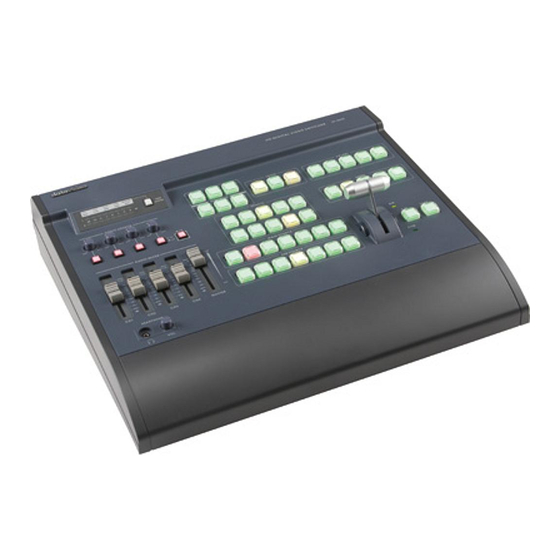
- Page 1 Digital Video Switcher SE-2000 INSTRUCTION MANUAL www.datavideo-tek.com...
-
Page 2: Table Of Contents
Contents Warnings and Precautions .......................... 4 Warranty ................................ 5 Standard Warranty........................... 5 Two Year Warranty ..........................5 Disposal ..............................5 Packing List ............................. 5 Introduction ..............................6 Product Overview ............................ 6 Features ..............................6 Connections & Controls ..........................7 Keyboard ..............................7 Audio mixer ............................ - Page 3 Disclaimer of Product and Services The information offered in this instruction manual is intended as a guide only. At all times, Datavideo Technologies will try to give correct, complete and suitable information. However, Datavideo Technologies cannot exclude that some information in this manual, from time to time, may not be correct or may be incomplete.
-
Page 4: Warnings And Precautions
7. This product should only be operated from the type of power source indicated on the marking label of the AC adapter. If you are not sure of the type of power available, consult your Datavideo dealer or your local power company. -
Page 5: Warranty
Certain parts with limited lifetime expectancy such as LCD Panels, DVD Drives, Hard Drives are only covered for the first 10,000 hours, or 1 year (whichever comes first). • Any second year warranty claims must be made to your local Datavideo office or one of its authorized Distributors before the extended warranty expires. Disposal For EU Customers only - WEEE Marking This symbol on the product indicates that it should not be treated as household waste. -
Page 6: Introduction
The brand new SE-2000 switcher not only meets your request for true full 1920 x 1080 HD quality, but also provides an array of simple-to-operate features, including up to 14 pre-stored logos, digital clock display, five user setup, DVI-D connection for use with presentation software and easy titling, and many more features. -
Page 7: Connections & Controls
Connections & Controls Keyboard 1. Audio mixer 7. Transition Speed 2. Audio input selectors / Level Controls 8. Transition Effects 3. Audio meters 9. CUT & TAKE 4. Menu and Controls 10. T-Bar 5. Logo & Clock Selection 11. Main and Sub Source selection 6. -
Page 8: Audio Mixer
Audio Input Source Selectors and Level Controls This section of the SE-2000 controls which audio input channel (CH1~CH4) will be sent to the Audio Bus and its associated Fader. This row of audio channel selection buttons has LEDs built in to show which input channel is active. -
Page 9: System Configuration Menu
System Configuration Menu Press the Menu button in the SE-2000 function section to enter the System Configuration Menu. Press the up, down, left, and right arrow buttons to navigate the menu options and to change values. Use the ENT button to save and confirm any setting that has been amended. -
Page 10: T-Bar
How to calibrate the T-bar: 1. Turn off the SE-2000 power, and push the T-Bar up as far as it can go to its Top or AIR position then move the T-Bar back down by 2mm. 2. Press and hold in the SET and SUB SOURCE 1 buttons at the same time. -
Page 12: Multi Preview Output
Supports two channels XLR Balanced Audio output. 12. AUDIO IN The SE-2000 supports four XLR Balanced Audio Input channels. There are two kinds of switches under AUDIO IN: The LINE/MIC switch is used to set the audio as LINE in or MIC in. -
Page 14: Main Source And Sub Source Rails
Main Source and Sub Source Rails The Main Source Rail shows the active channel, this is the Live output. The active channel will also appear as the Program Output (PGM). You can immediately switch or CUT from one input channel to another directly on the Main Source Rail, you will see the PROGRAM Output switch as you press different keys along this rail. -
Page 15: System Configuration Menu
System Configuration Menu Menu and Navigation Press the MENU button in the Function section of the SE-2000’s keyboard to enter the System Configuration Menu. The menu will be displayed on the SE-2000’s Multi Preview output as below. Press the UP, DOWN, LEFT and RIGHT arrow buttons to highlight or select a menu option. Then use the UP and DOWN arrow buttons to change the value of the selected item or option. -
Page 16: Pip Setting
If you want to enable the PIP function, you must first press the SET key in the PIP / KEY section of the SE-2000 keyboard, then press the PIP PVW key and then select the Sub Source channel required for the PIP window. -
Page 17: Mode Setting
Press the arrow buttons to select an item and press the ENT to confirm the setting. This mode is used to return the SE-2000 BASIC profile (USER 0) to its factory default settings. If the BASIC profile is changed then any USER profiles (1 ~ 5) linked to BASIC will also be changed. -
Page 18: Background
Press the arrow buttons to select an item and press the ENT to confirm the setting. This mode is used to set the clock within the SE-2000. The current Clock value is displayed in between the PREVIEW and PROGRAM windows of the Multi Preview Display. -
Page 19: Audio Inputs And Levels
NOTE: Audio cannot be de-embedded by the SE-2000 from a HD-SDI input and Audio will not be embedded into the SE-2000’s HD-SDI PGM outputs. For ideas on how best to do this before and after the SE-2000 mixer see Example SE-2000 Set Ups (Page 20). -
Page 20: Example Se-2000 Set Ups
Example SE-2000 Set Ups... -
Page 21: Se-2000 Configuration Utility
SE-2000 Configuration Utility The Configuration Utility software allows a PC (running Windows XP Professional) to make changes to the mixer*. A cable needs to be connected between the RS-232 port on the rear of the SE-2000 and the PC COM1 Serial port. -
Page 23: Setting Up A Luma Key Overlay With Powerpoint
Setting up a Luma Key overlay with PowerPoint The SE-2000 has 5 inputs. Input 5 is DVI only and this can be used to connect a DVI-D cable from a computer’s monitor/graphics card. The PC graphics card will need 2 connections 1 for the PC monitor and a spare DVI-D connection to go to input 5 on the SE-2000. -
Page 24: Hd-Sdi Cabling Advice
SDI signal received. The signal is attenuated because part of it is reflected back and does not make it to the receiver (SE-2000 for example); it is also distorted because the reflected signal mixes with the original signal causing it to distort as well as adding to the noise floor. -
Page 25: How To Update Se-2000 Firmware
How to update SE-2000 firmware From time to time Datavideo may release new firmware to either add new features or to fix reported bugs in the current mixer firmware. Customers can update the mixer firmware themselves if they wish or they can contact their local dealer or reseller for assistance should they prefer this method. - Page 26 Now turn the mixer ON. Once the application discovers the mixer it will check the firmware on the mixer and report if it needs updating. Click NEXT to start the update. You will be asked to confirm that you want to proceed click YES.
-
Page 27: Se-2000 Bespoke Tally Cabling Advice
This page shows information for people wishing to create their own bespoke cabling for the purpose of connecting an ITC-100 or TB-5 unit to the Tally Output connection on the rear of the SE-2000 mixer. If wish to have this option but do not have the necessary skills to make this cable then please contact your local dealer or Datavideo office who may be willing to assist in the creation of a cable. -
Page 28: Se-2000 Rs-232 Remote Control Protocol
115200 Data bits Parity None Stop bits Pin Assignment D-Sub 9pin Female The pin assignment of the Host Controller and SE-2000 is shown in the following table: Host SE-2000 Receive A (RX-) Transmit A (TX-) Transmit B (TX+) Receive B (RX+) ... -
Page 29: Crc (Crcl,Crch)
CRC (CRCL,CRCH) Check sum! It is transmitted lower byte first. All the bytes except the last 2 from the block are used to calculate the check sum. There must be 0x0000 after the check sum calculation including the last 2 bytes, if the data have been transmitted error free. - Page 30 unsigned short ComPort_Flag; unsigned short CMD_Length; unsigned char CMD_Buf[128]; void Cal_Checksum(void) int i; unsigned char crc_lo,crc_hi; unsigned char new_crc_lo,new_crc_hi; unsigned char temp; crc_lo=CMD_Buf[CMD_Length-2]; crc_hi=CMD_Buf[CMD_Length-1]; for(i=0;i<(CMD_Length-2);i++) temp=crc_lo^CMD_Buf[i]; new_crc_hi=CRC16_TABLE_HI(temp); // Reference to Table 1 new_crc_lo=CRC16_TABLE_LO(temp)^crc_hi; // Reference to Table 2 crc_lo=new_crc_lo; crc_hi=new_crc_hi; CMD_Buf[CMD_Length-2]=crc_lo;...
-
Page 31: Table 1. Lower Crc Byte Calculation Coefficients.(Hex)
Table 1. Lower CRC byte calculation coefficients.(Hex) 000h 0c1h 081h 040h 001h 0c0h 080h 041h 001h 0c0h 080h 041h 000h 0c1h 081h 040h 001h 0c0h 080h 041h 000h 0c1h 081h 040h 000h 0c1h 081h 040h 001h 0c0h 080h 041h 001h 0c0h 080h 041h 000h 0c1h 081h 040h 000h 0c1h 081h 040h 001h 0c0h 080h 041h 000h 0c1h 081h 040h 001h 0c0h 080h 041h 001h 0c0h 080h 041h 000h 0c1h 081h 040h... -
Page 32: Table 2. Higher Crc Byte Calculation Coefficients.(Hex
Table 2. Higher CRC byte calculation coefficients.(Hex 000h 0c0h 0c1h 001h 0c3h 003h 002h 0c2h 0c6h 006h 007h 0c7h 005h 0c5h 0c4h 004h 0cch 00ch 00dh 0cdh 00fh 0cfh 0ceh 00eh 00ah 0cah 0cbh 00bh 0c9h 009h 008h 0c8h 0d8h 018h 019h 0d9h 01bh 0dbh 0dah 01ah 01eh 0deh 0dfh 01fh 0ddh 01dh 01ch 0dch 014h 0d4h 0d5h 015h 0d7h 017h 016h 0d6h 0d2h 012h 013h 0d3h 011h 0d1h 0d0h 010h... -
Page 33: Table 3. Command Type
Table 3. Command Type COM (Hex) ARG (Hex) Description Sub source: Set SDI input port 1 Sub source: Set SDI input port 2 Sub source: Set SDI input port 3 Sub source: Set SDI input port 4 Sub source: Set SDI input port 5 Sub source: Set Black Screen Sub source: Set Colour Bar Main source: Set SDI input port 1... -
Page 34: Table 4. Response Code
Cut function Auto function PIP source: Set SDI input port 1 PIP source: Set SDI input port 2 PIP source: Set SDI input port 3 PIP source: Set SDI input port 4 PIP source: Set SDI input port 5 PIP display on Sub source PIP turn off on Sub source PIP display on Main source PIP turn off on Main source... -
Page 35: Table 5. Status Code (41 Bytes Reference Pages 35 & 37)
Table 5. Status Code (41 Bytes reference pages 35 & 37) Byte 1: Byte 2: Byte 3: Byte 4: Current_User_Number Input A Input B PIP_Input Byte 5: Byte 6: Byte 7: Byte 8: Effect Speed Speed_Value_0 Speed_Value_1 Byte 9: Byte 10: Byte 11: Byte 12: Speed_Value_2... - Page 36 Current_User_Number – current user number (0…5), number 0 corresponds to the Master User which other the other users settings and adjustments can be linked to. Input_A, Input_B, PiP_Input – input number currently switched to the multiplexor’s Line A, multiplexor’s Line B and PiP shaper input;...
- Page 37 Inp_3_Mode – the current input 3 mode, 0 – SDI, 1 – DVI; Link_Flags – Master user settings link flags, it may be unlinked(value 0) or linked(value1) to the corresponding basic parameter: bit 7 – input 0 settings link flag (brightness, contrast, saturation), bit 6 –...
-
Page 38: Optional Datavideo Accessory Items For The Se-2000
Datavideo have a number of accessory products which will allow you to get the most from your new SE-2000. Please speak to your local dealer or visit the website for your local Datavideo office for more details on these and other products. -
Page 40: Service And Support
It is our goal to make your products ownership a satisfying experience. Our supporting staff is available to assist you in setting up and operating your system. Please refer to our web site www.datavideo-tek.com for answers to common questions, support requests or contact your local office below.
Need help?
Do you have a question about the SE-2000 and is the answer not in the manual?
Questions and answers