Table of Contents
Advertisement
Owner's Operator and Maintenance Manual
Get-U-Up
Lift
™
DEALER: This manual MUST be given to the user of the patient lift.
USER: BEFORE using this patient lift, read this manual and save for future reference.
For more information regarding
Invacare products, parts, and services,
please visit www.invacare.com
Advertisement
Table of Contents

Related Manuals for Invacare GET-U-UP LIFT


Summary of Contents for Invacare GET-U-UP LIFT
- Page 1 ™ DEALER: This manual MUST be given to the user of the patient lift. USER: BEFORE using this patient lift, read this manual and save for future reference. For more information regarding Invacare products, parts, and services, please visit www.invacare.com...
-
Page 2: Symbol Legend
TECHNICAL PERSONNEL BEFORE ATTEMPTING TO USE THIS EQUIPMENT - OTHERWISE, INJURY OR DAMAGE MAY OCCUR. Invacare products are specifically designed and manufactured for use in conjunction with Invacare accessories. Accessories designed by other manufacturers have not been tested by Invacare and are not recommended for use with Invacare products. -
Page 3: Table Of Contents
SPECIAL NOTES ... 5 LABEL LOCATIONS ... 6 TYPICAL PRODUCT PARAMETERS ... 7 SECTION 1—GENERAL GUIDELINES ... 8 Weight Limitation ...8 Assembling the Lift...8 Using the Sling...8 Operating the Lift...9 Lifting the Patient ...9 Transferring the Patient...9 Performing Maintenance...9 SECTION 2—ASSEMBLY... 10 Attach the Mast to the Base Assembly ... - Page 4 SECTION 8—MAINTENANCE ... 25 Maintenance Safety Inspection Checklist... 25 Hydraulic Pump... 25 Lubricating the Lift ... 26 Detecting Wear and Damage... 26 Cleaning the Sling and the Lift... 26 Replacing the Knee Pad ... 26 LIMITED WARRANTY ... 27 ™ Get-U-Up Lift TABLE OF CONTENTS...
-
Page 5: Special Notes
Signal words are used in this manual and apply to hazards or unsafe practices which could result in personal injury or property damage. Refer to the table below for definitions of the signal words. SIGNAL WORD DANGER WARNING CAUTION THE INFORMATION CONTAINED IN THIS DOCUMENT IS SUBJECT TO CHANGE WITHOUT NOTICE. Check ALL parts for shipping damage. If shipping damage is noted, DO NOT use. Contact dealer/carrier for further instruction. MAINTENANCE Maintenance MUST be performed ONLY by qualified personnel. Part No 1148115 SPECIAL NOTES Danger indicates an imminently hazardous situation which, if not avoided, will result in... -
Page 6: Label Locations
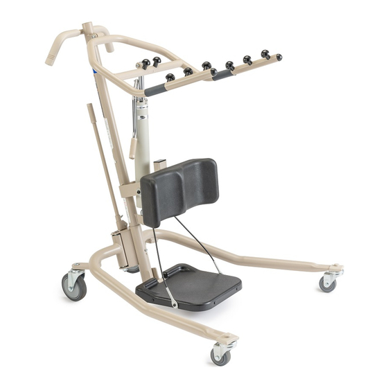
OPERATION OF THE PATIENT LIFT The mast (C) includes the steering handles used to move and guide the lift. The mast is supported in a socket in the rear center of the base with casters (A). For transporting the lift in a vehicle, the mast, boom and pump assembly may be lifted from the base socket for convenient storage. -
Page 7: Typical Product Parameters
TYPICAL PRODUCT PARAMETERS HEIGHT AT SLING HOOK-UP - MAX. HEIGHT AT SLING HOOK-UP - MIN. BASE WIDTH OPEN BASE WIDTH CLOSED BASE HEIGHT (CLEARANCE) BASE LENGTH OVERALL HEIGHT OVERALL LENGTH OVERALL WIDTH CASTER SIZE (REAR/FRONT) SLING OPTIONS SLING MATERIAL STANDING SLING WIDTH LENGTH TRANSPORT SLING... -
Page 8: Section 1-General Guidelines
SECTION 1—GENERAL GUIDELINES SECTION 1—GENERAL GUIDELINES WARNING SECTION 1 - GENERAL GUIDELINES contains important information for the safe operation and use of this product. Check all parts for shipping damage before using. In case of damage, DO NOT use the equipment. Contact the dealer for further instructions. The Invacare patient lift is NOT a transport device. It is intended to transfer an individual from one resting surface to another (such as a bed to a wheelchair). Moving a person suspended in a sling over ANY distance is NOT recommended. DO NOT attempt to transfer without the approval of the patient’s physician, nurse or medical assistant. Thoroughly read the instructions in this Owner’s Manual, observe a trained team of experts performing the lifting procedures and then perform the entire lift procedure several times with proper supervision and a capable individual acting as a patient. Invacare Stand Assist and Transfer slings are specifically designed to be used in conjunction with Invacare patient lifts. Slings and accessories designed by other manufacturers are not to be utilized as a component of Invacare’s patient lift system. Use the sling that is recommended by the individual’s doctor, nurse or medical assistant for the comfort and safety of the individual that is being lifted. Weight Limitation DO NOT exceed the maximum weight limitation of the patient lift. The Get‐U‐Up lift has a weight limitation ... -
Page 9: Operating The Lift
SECTION 1—GENERAL GUIDELINES DO NOT alter slings. Be sure to check the sling attachments each time the sling is removed and replaced, to ensure that it is properly attached before the patient is removed from a stationary object (bed, chair or commode). If the patient is in a wheelchair, secure the wheel locks in place to prevent the chair from moving forwards or backwards. When connecting slings equipped with color coded straps to the patient lift, the shortest of the straps MUST be at the back of the patient for support. Using long section will leave little or no support for the patient’s back. The loops of the sling are color coded and can be used to place the patient in various positions. The colors make it easy to connect both sides of the sling equally. Make sure that there is sufficient head support when lifting a patient. Use an Invacare sling that is recommended by the individual’s doctor, nurse or medical assistant for the comfort and safety of the individual being lifted. Operating the Lift Make sure there is an audible click when mounting battery on the battery charger to confirm proper mounting. Otherwise, injury or damage may occur. Use the handles to push or pull the patient. Lifting the Patient Before positioning the legs of the stand up lift around the patient, make sure that the patient’s feet are out of the way of the foot plate, otherwise injury may occur. Adjustments for safety and comfort should be made before moving the patient. Patient’s arms should be outside of the sling straps. Before lifting a patient from a stationary object (wheelchair, commode or bed), slightly raise the patient off of the stationary object and check that all sling attachments are secure. If any attachment is not correct, lower the patient and correct the problem, then raise the patient and check again. During transfer, with the patient suspended in a sling attached to the lift, DO NOT roll caster base over objects such as carpet, raised carpet bindings, door frames, or any uneven surfaces or obstacles that would create an imbalance of the patient lift to tip over. Use the steering handle on the mast at ALL times to push or pull the patient lift. Invacare recommends locking the rear swivel casters ONLY when positioning or removing the sling (stand assist or transfer) from around the patient. Transferring the Patient Before transferring, check that the product’s weight capacity can withstand the patient’s weight. -
Page 10: Section 2-Assembly
SECTION 2—ASSEMBLY Each time the mast is removed and assembled to the base assembly, the mast MUST be locked into the socket of the base assembly. Attach the Mast to the Base Assembly NOTE: For this procedure, refer to FIGURE 2.1. Remove the locking screw from the base assembly. Match the notch at the bottom of the mast with the tabs inside the socket of the base assembly. Insert the mast into the socket and onto the tabs. Try to turn the mast. NOTE: If the mast turns in the socket, repeat STEPS 2 and 3 until proper alignment is obtained. If the mast does not turn in the socket, insert the locking screw into the base and tighten securely. -
Page 11: Attach The Horn To The Mast And Actuator
CAUTION The horn MUST pivot easily. At the attachment point of the horn to the mast assembly, use an Allen wrench to hold the locknut and turn the shoulder bolt by hand (it should rotate without a lot of force being applied). Raise the horn. Push the control handle away from the pump assembly. If the horn pivots easily, tighten the shoulder bolt and locknut. NOTE: If the horn does not pivot easily or not at all, remove the locknut and shoulder bolt. Check all hardware for proper alignment. Reinstall hardware and repeat STEPS 1‐4. If alignment problems continue, contact the Technical Support Department at Invacare. Part No 1148115 Horn Horn Bushing Shoulder Bolt and Steel Nylon Washer Washers Locknut and Steel Washer Cylinder Lugs Locknut Actuator Cylinder Rod FIGURE 2.2 Attach the Horn to the Mast and Actuator... -
Page 12: Attaching/Adjusting The Knee Pad
Attaching/Adjusting the Knee Pad NOTE: For this procedure, refer to FIGURE 2.3. WARNING Never adjust knee pad while patient is in the standing position or while the lift is moving. Always make sure that the adjustment pins are fully engaged in the height adjustment holes before use. Pick a height setting that will be comfortable to the ... -
Page 13: Section 3-Operation
Invacare slings and lift accessories are specifically designed to be used in conjunction with Invacare lifts. Slings and accessories designed by other manufacturers are not to be utilized as a component of Invacare’s lift system. DO NOT exceed maximum weight limitation of the lift. The weight limitation for the Get-U-Up Lift is 350 lbs. -
Page 14: Operating The Lift
Operating the Lift NOTE: For this procedure, refer to FIGURE 3.1. Opening the Legs Stand at the rear of the lift and grasp the shifter handle in one‐hand and place the opposite hand on the steering handle of the mast for balance. Refer to Details “A” and “B”. Push the shifter handle to your right to release the lock pin from its mounting hole. Turn the handle clockwise until you are able to secure the lock pin into the opposite mounting hole to fully open the legs of the base. Refer to Detail “C”. NOTE: The lock pin MUST insert into its mounting hole in the socket assembly to lock the legs in the full open position. The shifter handle will be in the vertical position and parallel with the mast assembly. If the shifter handle is NOT vertical, the lock pin is NOT seated in the socket assembly. DO NOT use the lift until the lock pin is properly seated and locked in place or injury and/or damage may occur. Closing the Legs Stand at the rear of the lift and grasp the shifter handle in one‐hand. -
Page 15: Raising/Lowering Model Hydraulic Lifts
SECTION 3—OPERATION Raising/Lowering the Hydraulic Lift NOTE: For this procedure, refer to FIGURE 3.2. Raising the Lift NOTE: Ensure the control valve is in the closed position (control valve positioned towards pump handle). Move the pump handle up and down to raise the lift. Lowering the Lift NOTE: Ensure the control valve is in the open position (control valve positioned away from pump handle). NOTE: The weight of the person on the lifting arm causes the lift arm to lower when the control valve is open. NOTE: The rate of descent is controlled by varying the amount that the control valve is opened. A safety gate is part of the hydraulic system that maintains a SLOW constant descent of the boom regardless of how far the control valve is opened. Pump Handle Pump Handle Closed Open Control Valve FIGURE 3.2 Raising/Lowering the Hydraulic Lift ™ Part No 1148115 Get-U-Up Lift... -
Page 16: Section 4-Lifting
DO NOT attempt any transfer without approval of the patient’s physician, nurse or medical assistant. Invacare patient slings are made specifically for use with Invacare patient lifts. For the safety of the patient, DO NOT intermix patient slings and patient lifts of different manufacturers. -
Page 17: Lifting The Patient
Lifting the Patient DO NOT exceed the maximum weight limitation of 350 lbs. DO NOT use slings and stand up lifts of different manufacturers. Invacare slings are made specifically for use with Invacare stand up lifts. Injury or damage may occur. -
Page 18: Moving The Patient
Casters Moving the Patient DO NOT move a person suspended in a sling any distance. The Invacare lift is NOT a transport device. It is intended to transfer a seated individual from one resting surface to another (such as a bed to a wheelchair). Otherwise, injury or damage may occur. -
Page 19: Section 5-Transferring
DO NOT use slings and stand up lifts of different manufacturers. Invacare slings are made specifically for use with Invacare stand up lifts. Otherwise, injury or damage may occur. -
Page 20: Transferring To A Commode
Transferring to a Commode NOTE: For this procedure, refer to FIGURE 5.1. Raise the patient high enough to clear the arms of the commode chair. Their weight will be supported by the lift. Refer to Detail “A”. Guide the patient onto the commode chair. Lower the patient onto the commode chair. Perform one of the following (refer to Detail “B” or “C”): • Standing Sling ‐ unhook the standing sling from the attachment points on the lift. • Transport Sling ‐ Unhook the transport sling from the bottom attachment points on the lift. ii. Lift up on the patient’s legs and remove the thigh supports from underneath the patient. iii. If desired, unhook the transport sling from the top attachment points on the lift. NOTE: The patient can remain in the upper portion of the transport sling while using the commode. Instruct or assist the patient in lifting their feet off the footplate. Remove the sling from around the patient. Pull the lift away from the commode. When complete, recheck the sling for correct attachments. To lift the patient from the commode, refer to Lifting starting on page 16. ™ Get-U-Up Lift DETAIL “A”... -
Page 21: Transferring To A Wheelchair
Transferring to a Wheelchair NOTE: For this procedure, refer to FIGURE 5.2. NOTE: Before transferring, check that the wheelchair weight capacity can withstand the patientʹs weight. Refer to Typical Product Parameters in the wheelchair owner’s manual Ensure the legs of the lift with the patient in the sling are in the open position. Move the wheelchair into position. Refer to Detail “A”. Engage the rear wheel locks of the wheelchair to prevent movement of the wheelchair. Refer to Detail “B”. WARNING DO NOT place the patient in the wheelchair if the locks are not engaged. The wheelchair wheel locks MUST be in a locked position before lowering the patient into the wheel- chair for transport. -
Page 22: Transferring To A Bed
Transferring to a Bed NOTE: For this procedure, refer to FIGURE 5.3. NOTE: The lower center of gravity provides stability making the patient feel more secure and the lift easier to move. NOTE: The lift arms will stay in position until lowered. Position the patient as far over the bed as possible. NOTE: If patient is being transferred from a surface that is lower than the bed, raise the patient above the surface of the bed. The patient should be elevated just high enough to clear the bed with their weight fully supported by the lift. Lower the patient onto the bed. Unhook the sling from all attachment points on the lift. Instruct the patient to lift their feet off of the footplate. Assist the patient if necessary. Remove the standing or transport sling from around the patient. Pull the lift away from the bed. ™ Get-U-Up Lift DETAIL “A” - LOWERING DETAIL “B” - UNHOOKING THE SLING FIGURE 5.3 Transferring to a Bed Part No 1148115... -
Page 23: Section 6-Using The Patient Lift As A Standing Aid
SECTION 6—USING THE PATIENT LIFT AS A STANDING NOTE: For this procedure, refer to FIGURE 6.1. NOTE: The Get‐U‐Up lift can be used as an aid to lift a person from a seated to a standing position. A minimum of two caregivers is required for this procedure. NOTE: Invacare recommends that two assistants be used for all lifting preparation and transferring to/from procedures; however, our equipment will permit proper operation by one assistant. The use of one assistant is based on the evaluation of the health care professional for each individual case. Standing Procedure Ensure that the patient is capable of walking. Fold the footplate toward the mast. Use the adjustment pins to move the kneepad to a comfortable position. Ensure that the patient is in a sitting position to begin the procedure. A. If the patient is in bed and requires assistance to come to a sitting position, raise the back of the bed. B. Place the lift over the bed with the lift arms angled toward the patient. C. Instruct the patient to grasp the lift arms. D. As the lift arms are raised, the patient should move legs to the side of the bed until a sitting position on the side of the bed is assumed. NOTE: The caregivers should assist as needed. E. Pull the lift away as needed to accommodate the ... -
Page 24: Section 7-Troubleshooting
SECTION 7—TROUBLESHOOTING SYMPTOMS Stand up lift feels loose. Casters/brakes noisy or stiff. Noisy or dry sound from pivots. Lift arms will not lower in uppermost position. NOTE: If problems are not remedied by the suggested means, please contact your dealer or Invacare. ™ Get-U-Up Lift FAULTS Mast/base joint loose. Tighten the bolt, washer and locknut that secure the Tie-rods are loose. -
Page 25: Section 8-Maintenance
DO NOT attempt to open the hydraulic pump or obtain local service. This will void the warranty and might result in damage and costly repair. Consult your dealer or contact Invacare for information. Part No 1148115... -
Page 26: Lubricating The Lift
Lubricating the Lift A six month check and lubrication should ensure continued safety and reliability of the patient lift. The casters MUST swivel and roll smoothly. A light grease (waterproof auto lubricant) may be applied to the ball bearing swivel of the casters once a year. Apply more frequently if the casters are exposed to extreme moist conditions. Lubricate all pivot points. Wipe all excess lubricant from lift surface. The connection between the mast and the base should be cleaned and coated with petroleum jelly prior to assembly. Detecting Wear and Damage It is important to inspect all stressed parts, such as slings, sling attachment knobs, and any pivot for slings for signs of cracking, fraying, deformation or deterioration. Replace any defective parts immediately and ensure that the lift is not used until repairs are made. All sling metal parts should be inspected every three months and if wear is apparent, replacement must be made. Check that all labels are present and legible. Replace if necessary. Cleaning the Sling and the Lift The sling should be washed regularly in water temperature of 180°F (82°C) and a biological solution. A soft cloth, dampened with water and a small amount of mild detergent, is all that is needed to clean the lift. The lift can be cleaned with non‐abrasive cleaners. Replacing the Knee Pad NOTE: For this procedure, refer to FIGURE 8.1. Remove the four button screws and washers that secure existing knee pad to the lift. Remove the existing knee pad from the lift. Position the mounting holes in the new knee pad with the mounting holes in the lift. Using the existing hardware, secure the new knee pad to the lift. Knee Pad Adjustment Pin (1 of 2) ™... -
Page 27: Limited Warranty
If within such warranty period any such product shall be proven to be defective, such product shall be repaired or replaced, at Invacare’s option. This warranty does not include any labor or shipping charges incurred in replacement part installation or repair of any such product. - Page 28 800-333-6900 800-668-5324 All rights reserved. Trademarks are identified by the symbols ™ and ®. All trademarks are owned by or licensed to Invacare Corporation or its subsidiaries unless otherwise noted. ©2009 Invacare Corporation Part No 1148115 Rev B - 06/09...
Need help?
Do you have a question about the GET-U-UP LIFT and is the answer not in the manual?
Questions and answers