
Related Manuals for Grunaire GSU091HX


Summary of Contents for Grunaire GSU091HX
-
Page 1: Service Manual
SERVICE MANUAL DC Inverter Multi-Split Air-Condition Unit Indoor Unit Outdoor Unit GSU091HX GSU091HX GSU121HX GSU121HX GSU181HX GSU181HX GSU241HX GSU241HX REFRIGERENT HEAT PUMP R410A GRUNAIRE HX SERIES SERVICE MANUAL... - Page 2 ELECTRICAL DATA ..................... 7-1 WIRING DIAGRAMS ................... 8-1 REFRIGERATION DIAGRAMS ................9-1 10. TUBING CONNECTIONS ..................10-1 11. CONTROL SYSTEM ................... 11-1 12. TROUBLESHOOTING ..................12-1 13. EXPLODED VIEWS AND SPARE PARTS LISTS ..........13-1 14. APPENDIX A GRUNAIRE HX SERIES SERVICE MANUAL...
-
Page 3: Main Features
INTRODUCTION General The new grunaire HX series minisplit is a high efficiency DC inverter technology outdoor unit, It can be matched to several inverter indoor units such as wall mounted type with a capacity range of 9000 – 12000 BTU for each single indoor unit. - Page 4 38.6×15.7×26.0 38.2×15.6×29.9 40.2×17.1×34.1 Outdoor Dimensions W x D x H(In.) 36.2×13.2×23.0 39.2×16.3×26.8 39.0×16.1×30.3 40.6×17.3×37.8 Outdoor Package Dimensions W x D x H(In.) Outdoor Net Weight (lbs.) Outdoor Gross Weight(lbs. ) R410A R410A R410A R410A Refrigerant GRUNAIRE HX SERIES SERVICE MANUAL...
- Page 5 49.21' Connection Charge over Design Length 0.20 oz / Ft. 0.20 oz / Ft. 0.20 oz / Ft. Connection Pipes 1/4" / 3/8" 1/4" x 1/2" 1/4" x 1/2" Design Pressure (PSI) 623.66 623.66 623.66 GRUNAIRE HX SERIES SERVICE MANUAL...
- Page 6 Unit Dimensions (W x H x D) (in) 36.61 x 10.83 x 8.27 Packing Dimensions W x H x D) (in) 39.96 x 13.97 x 12.79 Net / Gross Wt (lbs) 30.86 / 37.48 Dehumidifying Volume (pt/hr) 3.03 Auto-restart GRUNAIRE HX SERIES SERVICE MANUAL...
- Page 7 Unit Dimensions (W x H x D) (in) 36.61 x 10.83 x 8.27 Packing Dimensions W x H x D) (in) 39.96 x 13.97 x 12.79 Net / Gross Wt (lbs) 30.86 / 37.48 Dehumidifying Volume (pt/hr) 3.03 Auto-restart GRUNAIRE HX SERIES SERVICE MANUAL...
- Page 8 Unit Dimensions (W x H x D) (in) 36.61 x 10.83 x 8.27 Packing Dimensions W x H x D) (in) 39.96 x 13.97 x 12.79 Net / Gross Wt (lbs) 30.86 / 37.48 Dehumidifying Volume (pt/hr) 3.03 Auto-restart GRUNAIRE HX SERIES SERVICE MANUAL...
- Page 9 Unit Dimensions (W x H x D) (in) 36.61 x 10.83 x 8.27 Packing Dimensions W x H x D) (in) 39.96 x 13.97 x 12.79 Net / Gross Wt (lbs) 30.86 / 37.48 Dehumidifying Volume (pt/hr) 3.03 Auto-restart GRUNAIRE HX SERIES SERVICE MANUAL...
- Page 10 Unit Dimensions (W x H x D) (in) 36.61 x 10.83 x 8.27 Packing Dimensions W x H x D) (in) 39.96 x 13.97 x 12.79 Net / Gross Wt (lbs) 30.86 / 37.48 Dehumidifying Volume (pt/hr) 3.03 Auto-restart GRUNAIRE HX SERIES SERVICE MANUAL...
- Page 11 Unit Dimensions (W x H x D) (in) 36.61 x 10.83 x 8.27 Packing Dimensions W x H x D) (in) 39.96 x 13.97 x 12.79 Net / Gross Wt (lbs) 30.86 / 37.48 Dehumidifying Volume (pt/hr) 3.03 Auto-restart GRUNAIRE HX SERIES SERVICE MANUAL...
- Page 12 Unit Dimensions (W x H x D) (in) 36.61 x 10.83 x 8.27 Packing Dimensions W x H x D) (in) 39.96 x 13.97 x 12.79 Net / Gross Wt (lbs) 30.86 / 37.48 Dehumidifying Volume (pt/hr) 3.03 Auto-restart GRUNAIRE HX SERIES SERVICE MANUAL...
- Page 13 F WB 3 . 1 O p e r a t i n g L i mi t s Outdoor Cooling Upper limit (DB) Lower limit (DB) Heating Upper limit (DB) Lower limit (DB) 198–264V/115V Voltage GRUNAIRE HX SERIES SERVICE MANUAL...
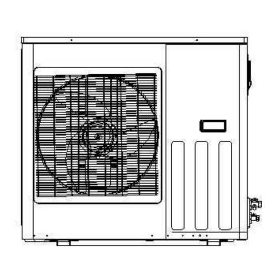
- Page 14 O U T LI N E DI M EN S I O NS outdoor Unit: GSU091HX outdoor Unit: GSU121HX GRUNAIRE HX SERIES SERVICE MANUAL...
- Page 15 4.3 outdoor Unit: GSU181HX 4.4 outdoor Unit: GSU241HX GRUNAIRE HX SERIES SERVICE MANUAL...
- Page 16 4.5 outdoor Unit:HX-50V9A-S 4.6 outdoor Unit:HX-V64T9AD GRUNAIRE HX SERIES SERVICE MANUAL...
- Page 17 4.7 outdoor Unit:HX-V64WC9A GRUNAIRE HX SERIES SERVICE MANUAL...
- Page 18 TC – Total Cooling Capacity, BTU SC – Sensible Capacity, BTU PI – Power Input, kW WB – Wet Bulb Temp., ( DB – Dry Bulb Temp., ( ) ID – Indoor OD – Outdoor GRUNAIRE HX SERIES SERVICE MANUAL...
- Page 19 85 - 105 % of nominal 59~75 (Protection Range) 80 - 120 % of nominal 5.1.1.3 Capacity Correction Factors Cooling Capacity Ratio Vs. Outdoor Temperature Cooling Capacity Correction Factor 90/73 84/70 81/66 75/63 72/59 Outdoor Temp.(deg F) GRUNAIRE HX SERIES SERVICE MANUAL...
- Page 20 Heating Capacity Ratio Vs. Outdoor Temperature Heating Capacity Correction Factor Outdoor Temp.(deg F) GRUNAIRE HX SERIES SERVICE MANUAL...
- Page 21 0.88 0.90 0.92 0.93 0.94 9936 10704 11424 12192 12960 9634 9815 10058 10239 10482 0.97 0.98 0.99 1.01 1.02 9264 10032 10752 11520 12288 9270 9512 9694 9936 10118 1.07 1.08 1.09 1.11 1.13 GRUNAIRE HX SERIES SERVICE MANUAL...
- Page 22 85 - 105 % of nominal 59~75 (Protection Range) 80 - 120 % of nominal 5.2.1.3 Capacity Correction Factors Cooling Capacity Ratio Vs. Outdoor Temperature Cooling Capacity Correction Factor 90/73 84/70 81/66 75/63 72/59 Outdoor Temp.(deg F) GRUNAIRE HX SERIES SERVICE MANUAL...
- Page 23 1.46 1.48 1.52 1.54 1.56 14904 16056 17136 18288 19440 14310 14580 14940 15210 15570 1.60 1.62 1.64 1.66 1.68 13896 15048 16128 17280 18432 13770 14130 14400 14760 15030 1.77 1.79 1.81 1.83 1.87 GRUNAIRE HX SERIES SERVICE MANUAL...
- Page 24 85 - 105 % of nominal 59~75 (Protection Range) 80 - 120 % of nominal 5.2.3.3 Capacity Correction Factors Cooling Capacity Ratio Vs. Outdoor Temperature Cooling Capacity Correction Factor 90/73 84/70 81/66 75/63 72/59 Outdoor Temp.(deg F) GRUNAIRE HX SERIES SERVICE MANUAL...
- Page 25 2.11 2.14 2.20 2.23 2.26 19872 21408 22848 24384 25920 19080 19440 19920 20280 20760 2.32 2.35 2.38 2.41 2.44 18528 20064 21504 23040 24576 18360 18840 19200 19680 20040 2.56 2.59 2.62 2.65 2.71 GRUNAIRE HX SERIES SERVICE MANUAL...
- Page 26 85 - 105 % of nominal 59~75 (Protection Range) 80 - 120 % of nominal 5.2.4.3 Capacity Correction Factors Cooling Capacity Ratio Vs. Outdoor Temperature Cooling Capacity Correction Factor 90/73 84/70 81/66 75/63 72/59 Outdoor Temp.(deg F) GRUNAIRE HX SERIES SERVICE MANUAL...
- Page 27 Outdoor Temp.(deg F) Capacity Correction Factor Due to Tubing Length (One Way) 5.3.1 Indoor units Model HXS-25V9A-A21A HX-V32G9A-H46 HXS-32V9A-A21A HX-V25G9A-A77 HXS-25V9A-A27A HX-V32G9A-H77 HXS-32V9A-A27A HX-V25G9A-A79 HXS-25V9A-A48A HX-V32G9A-H79 HXS-32V9A-A48A GSI091HX HX-V25G9A-A30 GSI121HX HX-V32G9A-H30 GSI181HX HX-V25G9A-A46 GSI241HX 5.3.1.1 Cooling GRUNAIRE HX SERIES SERVICE MANUAL...
- Page 28 5.3.1.2 Heating GRUNAIRE HX SERIES SERVICE MANUAL...
- Page 29 6. Pressure Curve Model GSU091HX HX-50V9A-S GSU121HX HX-V64WC9A GSU181HX HX-V64T9AD GSU241HX 6.1.1 Suction Pressure Curve 6.1.2 Discharge Pressure Curve GRUNAIRE HX SERIES SERVICE MANUAL...
- Page 30 Maximum Current 12.2A Inrush Current Starting Current Circuit breaker Power supply wiring - No. x cross section 1 X 3 X 2.5 mm 2 X 4 X 1 mm Interconnecting cable - No. x cross section GRUNAIRE HX SERIES SERVICE MANUAL...
- Page 31 Inrush current is the current when power is up. (charging the DC capacitors at outdoor unit controller). Starting current is the current when starting the compressor NOTE Power wiring cord should comply with local lows and electrical regulations requirements. GRUNAIRE HX SERIES SERVICE MANUAL...
- Page 32 G S U 0 9 1 H X W i r i n g D i a g r a m 8 . 2 G S U 1 2 1 H X W i r i n g D i a g r a m GRUNAIRE HX SERIES SERVICE MANUAL...
- Page 33 G S U 1 8 1 H X W i r i n g D i a g r a m 8 . 4 G S U 2 4 1 H X W i r i n g D i a g r a m GRUNAIRE HX SERIES SERVICE MANUAL...
- Page 34 8 . 6 H X - V 6 4 W C 9 A H X - V 6 4 T 9 A D W i r i n g D i a g r a m GRUNAIRE HX SERIES SERVICE MANUAL...
- Page 35 G S U 2 4 1 H X 8 . 6 I n d o o r - O u t d o o r W i r i n g D i a g r a m GRUNAIRE HX SERIES SERVICE MANUAL...
-
Page 36: Refrigeration Diagrams
G S U 0 9 1 H X R e f r i g e r a t i o n D i a g r a m 9 . 2 G S U 1 2 1 H X R e f r i g e r a t i o n D i a g r a m GRUNAIRE HX SERIES SERVICE MANUAL... - Page 37 R e f r i g e r a t i o n D i a g r a m 9 . 4 H X - 5 0 V 9 A - S R e f r i g e r a t i o n D i a g r a m GRUNAIRE HX SERIES SERVICE MANUAL...
- Page 38 H X - V 6 4 W C 9 A H X - V 6 4 T 9 A D R e f r i g e r a t i o n D i a g r a m GRUNAIRE HX SERIES SERVICE MANUAL...
- Page 39 When the outdoor unit is installed above the indoor unit an oil trap is required every 5m along the suction line at the lowest point of the riser. Incase the indoor unit is installed above the outdoor, no trap is required GRUNAIRE HX SERIES SERVICE MANUAL...
- Page 40 Ventilation: 60 F――90 F, default is 77 Sleeping It can set or cancel 24HR sleep . Timer on or timer off Timer can set 24HR on or off. Air flower control. GRUNAIRE HX SERIES SERVICE MANUAL...
- Page 41 Cooling 1280 1180 1080 speed Heating 1280 1180 1080 speed 18000BTU: mode high middle Cooling 1230 1000 speed Heating 1230 1000 speed 12000BTU: mode high middle Cooling 1000 speed Heating 1000 speed GRUNAIRE HX SERIES SERVICE MANUAL...
- Page 42 Fan speed is determined by the difference of room temp. and set temp. in auto wind. speed high middle ΔT It have anti freeze protection of indoor coil ,fan motor fault protection, sensor fault protection, unit abnormal protection in cooling mode. 2.Dehumidify:(ΔT=Troom temp.-Tset temp.) GRUNAIRE HX SERIES SERVICE MANUAL...
- Page 43 F,flap is open at 85°and is running at lower speed, when Tp Note:①When Tp≤86 ≥90 F, it is running at set speed and flap revert to prior state. ②If Tp≤77 F,turn off indoor blower fan. GRUNAIRE HX SERIES SERVICE MANUAL...
- Page 44 when it set timer , the timer lamp is light and display set temp. sleep If set sleep, the sleep lamp is light, set temp. and fan speed can be adjust. Timer and sleep can set together, which time is end then perform this function. GRUNAIRE HX SERIES SERVICE MANUAL...
- Page 45 When the temp. of middle coil pipe more than or equal to 135 F, indoor blower fan is running at high speed, if the temp. more than or equal to 149 F , it turn off outdoor GRUNAIRE HX SERIES SERVICE MANUAL...
-
Page 46: Other Function
Fault display of outdoor unit: fault display Transducer module protection Over current Discharge temperature of compressor overheat, ambient temperature overheat DC voltage of outdoor unit abnormal Leakage or reverse valve fault Outdoor sensor fault Compressor drive fault GRUNAIRE HX SERIES SERVICE MANUAL... - Page 47 Pressing Tubro for 5 times+Setting temp.89 H01:Indoor temp. 62 F,Compressor min H11:Indoor temp. 47 F,Compressor min H12:Indoor temp. 47 F,Compressor max H22:Indoor temp. 35 F,Compressor max H32:Indoor temp. 17 F,Compressor max H2V:Indoor temp. 35 F,Compressor mid GRUNAIRE HX SERIES SERVICE MANUAL...
- Page 48 Signal input of suction temperature of compressor e) Signal input of power supply voltage over-heat protection signal of compressor g) communication signal of indoor unit 1 h) communication signal of indoor unit 2 protection signal of outdoor IPM module GRUNAIRE HX SERIES SERVICE MANUAL...
- Page 49 3. The fan motor speed of outdoor unit as below table in normal running, it has 20 seconds delay after speed change. Speed table of outdoor fan motor indoor unit <2hp capacity ≥ ≥ outdoor ambient cooling Speed grade T<66 middle middle high F≤T<81 T≥81 middle high high GRUNAIRE HX SERIES SERVICE MANUAL...
- Page 50 1. The reverse valve is ahead run 20 seconds before compressor turn on. 2. After compressor turn off, the reverse valve delay 60 seconds shutdown. 3. The control of reverse valve as figure 6 during defrost process. GRUNAIRE HX SERIES SERVICE MANUAL...
- Page 51 Interval time(Td) change Td <2 minutes Last interval time add 5 minutes 3 minutes≥Td≥2 Same as last interval time minutes ≥4 minutes Last interval time reduce 5 minutes 4. Time sequence of defrost process(figure 6). GRUNAIRE HX SERIES SERVICE MANUAL...
- Page 52 30 seconds, it will display communication fault. If all communication channels are failure, air conditioner will shutdown and display fault code. GRUNAIRE HX SERIES SERVICE MANUAL...
- Page 53 1) The protection don’t effect if the temp. sensor of outdoor ambient fault. 2) The air conditioner stop running immediately and display error code if outdoor ambient temp. more than 131 F or less than -4 12. Over current protection of compressor GRUNAIRE HX SERIES SERVICE MANUAL...
- Page 54 十一、Outdoor unit fault of indoor unit display fault display Transducer module protection Over current Discharge temperature of compressor overheat, ambient temperature overheat DC voltage of outdoor unit abnormal Leakage or reverse valve fault Outdoor sensor fault Compressor drive fault GRUNAIRE HX SERIES SERVICE MANUAL...
-
Page 55: Troubleshooting
3,Temp. sensor of condenser middle short or cut off.---change sensor. P2:(auto-restart) 1,over current protection of inverter module. 2,over voltage protection of inverter module. 3,high temp. protection of inverter module. 1,over load (outdoor ambient temp. more high). 2,Voltage over low. GRUNAIRE HX SERIES SERVICE MANUAL... - Page 56 1,PFC board fault.---change PFC board. 2,Communication of main board and PFC board fault.---check wires of main board and PFC board. P8: 1,Less refrigerant.---add refrigerant. 2,Coil pipe sensor can’t contact with coil pipe. 3,4-way valve fault.---change 4-way vavle fault. GRUNAIRE HX SERIES SERVICE MANUAL...
- Page 57 1 3 . E X P L O D E D V I E W S AN D S P AR E P AR T S L I S T S 13.1 outdoor unit :GSU091HX description name number NO. description...
- Page 58 电机 Motor 干燥过滤器 Desiccation filter 轴流风机 Axial flow fan 右侧板 Right panel 前网罩 Front Grill 大抽手 Large handle 前面板 Front Plate 阀座板 Valve installation plate 左护网 Left protect net 低压阀 Low-pressure valve 左侧板 Left panel GRUNAIRE HX SERIES SERVICE MANUAL...
- Page 59 Left panel 阀座板 Valve installation plate 电机支架 Motor support 低压阀 Low-pressure valve 冷凝器 Condenser 高压阀 High-pressure valve 顶盖板 Top panel 维修板 Maintenance plate 电器盒 Electric box 压缩机 Compressor 背网 Rear Grill 中隔板 Partition board 底盘 Base GRUNAIRE HX SERIES SERVICE MANUAL...
- Page 60 Right panel 轴流风机 Axial flow fan 电器盒盖 Top of the Electric box 前网罩 Front Grill 阀座板 Valve installation plate 前面板 Front Plate 低压阀 Low-pressure valve 左护网 Left protect net 高压阀 High-pressure valve 左侧板 Left panel GRUNAIRE HX SERIES SERVICE MANUAL...
- Page 61 Maintenance plate 电器盒 Electric box 干燥过滤器 Desiccation filter 背网 Rear Grill 压缩机 Compressor Steam liquid 汽液分离器 中隔板 Partition board segregator Four-way valve 四通阀组件 底盘 Base assembly Electronic 电子膨胀阀 电 机 Motor expansion valve 右侧板 Right panel GRUNAIRE HX SERIES SERVICE MANUAL...
- Page 62 小抽手 Small handle 中隔板 Partition board 干燥过滤器 Desiccation filter 电器盒 Electric box 压缩机 Compressor 四通阀组件 Four-way valve assembly 油汽分离器 Oil and steam separator 电子膨胀阀 Electronic expansion valve 底盘 Base 右侧板 Right panel 电 机 Motor GRUNAIRE HX SERIES SERVICE MANUAL...
- Page 63 APPENDIX A INSTALLATION AND OPERATION MANUAL INSTALLATION MANUAL HX GRUNAIRE HX SERIES SERVICE MANUAL...
- Page 64 INSTALLATION/SERVICE TOOLS (ONLY FOR R410A PRODUCT) REFRIGERANT TUBING FINAL TASKS NOTE: This manual is for Multi split applications only. For indoor units installation please refer to the installation manual supplied within the indoor unit packa GRUNAIRE HX SERIES SERVICE MANUAL...
- Page 65 1 LOCATION OF OUTDOOR UNIT Select the location considering the following: O U T D O O R U N I T 1 .The location must allow easy servicing and provide good air circulation as shown in fig2. 2.The unit may be suspended from a wall by a bracked(Optional)or located in a free standing position on the floor(preferably slightly elevated).
- Page 66 2 ELECTRICAL CONNECTION BETWEEN OUTDOOR AND INDOOR UNIT ELECTRICAL REQUIREMENTS Electrical wiring and connections should be made by qualified electricians and in accordance with local electrical codes and regulation.The air conditioner units must be grounded. The air conditioner units must be connected to an adequate power outlet from a separate branch circuit protected by a time delay circuit breaker,as specified on unit's nameplate.
- Page 67 3 INSTALLATION/SERVICE TOOLS (ONLY FOR R410A PRODUCT) C A U T I O N New Refrigerant Air Conditioner Installation This air conditioner adopts the new HFC refrigeran t (R410A) which does not destroy ozone layer. R410A refrigerant is approx . 1.6 times of refigerant R22. Accompanied with the adoption of the new refrigerant , the refrigeration machine oil has also been changed.
- Page 68 By incressing the clamp bar'receiving hole Flare tool size , strength of spring in the tool has been (clutch type) improved. Gauge for projection Used when flare is made by using conventional adjustment flare tool. Connected to conventional vacuum pump,it is necessary to use an adapter to prevent vacuum pump oil from flowing back into the charge Vacuum pump adapter...
-
Page 69: Refrigerant Tubing
4 REFRIGERANT TUBING CONNECT THE INDOOR TO THE OUTDOOR UNIT The indoor unit contains a small quantity of nitrogen.Do not unscrew the nuts from the unit until you are ready to connect the tubing.The outdoor unit is supplied with suffcient refrigerant charge(R410A). Refer to outdoor unit nameplate. - Page 70 Tightening torques of unions and valve caops: TUBE SIZE TORQUE Liquid line 1/4" 1 5 - 2 0 N.M. Suction line 3/8" 3 0 - 3 5 N.M. Suction line 1/2" 5 0 - 5 4 N.M. Suction line 5/8" 7 5 - 7 8 N.M.
- Page 71 1 .Charging set 5.Cap 9.Liquid valve 2.Vacuum pump 6.Suction valve 10.INDOOR UNIT 3.OUTDOOR UNIT 7.Service valve 1 1.Suction flare connection 4.Service valve 8.Cap 12.Liquid flare connection 5 FINAL TASKS 1 .Check all valve caps and ensure that they had tightened properly.Close the valve cover. 2.Fill gaps on the wall between hole sides and tubing with sealer.
Need help?
Do you have a question about the GSU091HX and is the answer not in the manual?
Questions and answers