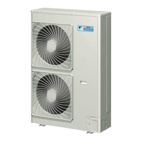
Summary of Contents for Daikin RMXS48LVJU
-
Page 1: Installation Manual
INSTALLATION MANUAL Installation manual English Manuel d’installation Français Manual de instalación Español Model RMXS48LVJU... -
Page 2: Table Of Contents
CONTENTS 1. SAFETY PRECAUTIONS ............1 7. PRECAUTIONS ON REFRIGERANT PIPING......8 7-1. Installation tools ..............8 2. INTRODUCTION..............3 7-2. Selecting piping material ........... 8 2-1. Combination ..............3 7-3. Protection against contamination when installing pipes..8 2-2. Standard operation limit ............ 3 7-4. - Page 3 WARNING • Installation shall be left to the authorized dealer or another trained professional. Improper installation may cause water leakage, electrical shock, fire, or equipment damage. • Install the air conditioner according to the instructions given in this manual. Incomplete installation may cause water leakage, electrical shock, fire or equipment damage. •...
-
Page 4: Introduction
This series uses R410A new refrigerant. Be absolutely sure to comply with “7. PRECAUTIONS ON REFRIGERANT PIPING”, Standard operation limit”. because even greater caution is needed to prevent impurities RMXS48LVJU Model name from entering R410A (mineral oils and water). Remarks... -
Page 5: Standard Supplied Accessories
2-5 Standard supplied accessories • Safe places which can withstand the unit’s weight and vibration and where the unit can be installed level. Make sure that the accessories shown below are all present. • Locations not exposed to rain. (The accessories can be found behind the front panel.) •... - Page 6 In case of installing multiple units (2 units or more) in lateral con- inch (mm) nection per row • In case obstacles exist in front of the air inlet and on both sides 0 < L ≤ 1/2H 10 (250) of the unit (Refer to figure 4-[3]) 1/2H <...
-
Page 7: Precautions On Installation
PRECAUTIONS ON INSTALLATION 6-1 Wiring connection example for whole system • Electrical wiring work should be done by a certified professional. • Install making sure the unit is level and the foundation is sturdy • Follow the “Electrical wiring diagram face plate” when carrying out enough to prevent vibration noise. -
Page 8: How To Lay The Power Supply Wiring And Transmission Wiring
Voltage current operating 4. Knockout hole for fuses current 5. Sideways 6. Forward RMXS48LVJU 60Hz 208/230V 7. Electrical Component Box CAUTION 8. Terminal block (X2M) 9. Binding band (accessory) • The wiring should be selected in compliance with local specifi- 10. -
Page 9: Inter-Unit Wiring Connection Procedure
6-4 Inter-unit wiring connection procedure • Piping work should be done within the maximum length, height difference, and length after branches set out in “7-8 Air tight test • Between indoor units in the same system, pass the wiring and vacuum drying”. between the units as shown in figure 17. -
Page 10: Heat Insulation Of Piping
• When connecting the pipings downward, remove the knock- (Refer to figure 24-[2]) 1. Rear-side connection out by making 4 holes in the middle on the each side of the 2. Gas side accessory pipe (1) knockout with a drill. 3. -
Page 11: Example Of Connection
7-7 Example of connection English... -
Page 12: Air Tight Test And Vacuum Drying
7-8 Air tight test and vacuum drying • Since the side boards may be deformed if only a torque wrench is used when loosening or tightening flare nuts, always lock the stop After doing the piping, perform the following inspections. valve with a wrench and then use a torque wrench. -
Page 13: Additional Refrigerant Charge
If all the refrigerant could not be added Location of “Cautions on Service” plate. Add refrigerant using the following procedure. See the “Cautions on The back of front panel Service” plate on the back of the front panel for details on the set- tings for adding refrigerant. -
Page 14: Test Run
10. TEST RUN <Precautions During Check Operation> • If operation is performed within 12 minutes of BP units and This unit is equipped with a crank case heater to ensure smooth outdoor units being turned on, H2P will light up, and the startup. -
Page 15: Caution For Refrigerant Leaks
Where the installation of a facility results in a concentration in excess of the maximum concentration level then it will be neces- Room where sary to revise the system. refrigerant leak Please consult your Daikin supplier. has occurred (outflow of all the refrigerant from the system) Pay a special attention to the place, such as a basement, etc. - Page 16 figure 1 figure 2 figure 3 unit : inch (mm) figure 4 figure 5 20 (500) or more 40 (1,000) 40 (1,000) or more or more 20 (500) or more 40 (1,000) or more unit : inch (mm) unit : inch (mm) figure 6 figure 7 L >...
- Page 17 figure 8 figure 9 figure 10 15/16 (20) 4 (100) unit : inch (mm) figure 11 4 (100) unit : inch (mm) figure 12 figure 13 5-1/2 (140) 5-1/2 (140) 24-3/8 (140) 1-3/4 (45) 16-5/8 (421) 24-1/8 (612) unit : inch (mm) figure 14 figure 15 figure 16...
- Page 18 figure 17 figure 18 figure 19 TO BP UNIT TO OUT/D UNIT F2 F1 F2 F1F2 F1F2 F1F2 F1F2 F1 F2 F1 F2 F1 F2 F1F2 F1F2 figure 20 figure 21 figure 22 figure 23 figure 24 figure 25 figure 26 figure 27 figure 28 figure 29...
- Page 19 Two-dimensional bar code is a code for manufacturing. 3P329623-1 M12B276 (1211)


Need help?
Do you have a question about the RMXS48LVJU and is the answer not in the manual?
Questions and answers