
Related Manuals for Kontron ETX CD


Summary of Contents for Kontron ETX CD
- Page 1 Kontron User's Guide ® ETX® CD ® Document Revision 1.0 All not approved entries are marked...
- Page 2 This page intentionally left blank...
-
Page 3: Table Of Contents
Connector X2 (ISA Bus) ...23 4.4.1 Connector X2 Signal Levels... 24 4.4.2 Connector X2 Signal Description... 26 Connector X3 (VGA, LCD, Video, COM1 and COM2, LPT/Floppy, Mouse, Keyboard) ... 26 Kontron User's Guide ETX CD ® XP SP2) ... 15 Table of Contents... - Page 4 Interrupt Request (IRQ) Lines ... 50 Direct Memory Access (DMA) Channels... 51 Memory Area ... 52 I/O Address Map ... 52 Peripheral Component Interconnect (PCI) Devices ... 52 Inter-IC (I2C) Bus... 52 Kontron User's Guide ETX CD Table of Contents...
- Page 5 12.1.2 PCI/104... 88 12.1.3 General PC Architecture ... 88 12.2 Ports... 89 12.2.1 RS-232 Serial ... 89 12.2.2 Serial ATA ... 89 12.2.3 USB ... 89 12.2.4 Programming ... 89 Appendix C: Document Revision...91 Kontron User's Guide ETX CD Table of Contents...
-
Page 6: User Information
IBM, XT, AT, PS/2 and Personal System/2 are trademarks of International Business ® Machines Corp. Microsoft is a registered trademark of Microsoft Corp. ® Intel is a registered trademark of Intel Corp. ® All other products and trademarks mentioned in this manual are trademarks of their ® respective owners. -
Page 7: Technical Support
4F, No.415, Ti-Ding Blvd., NeiHu District, Taipei 114, Taiwan Tel: +886 2 2799 2789 Fax: + 886 2 2799 7399 mailto:sales@kontron.com.tw Kontron User's Guide ETX CD Europe Kontron Embedded Modules GmbH Brunnwiesenstr. 16 94469 Deggendorf – Germany Tel: +49 (0) 991-37024-0 Fax: +49 (0) 991-37024-333 mailto:sales-kem@kontron.com... -
Page 8: Introduction
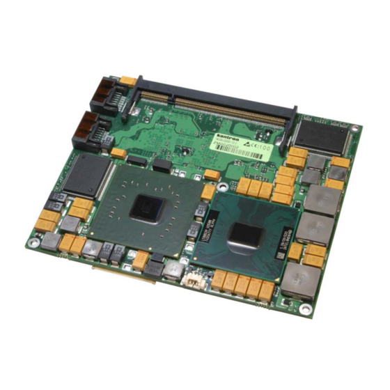
Advanced Configuration and Power Interface (ACPI) ® The ETX®-CD is built around the Intel Core Duo processors that use the Yonah and Merom Core and the Mobile Intel 945GME Express chipset, which is the first mobile platform to offer PCI Express functionality with extended life cycle support. -
Page 9: Etx® Documentation
A properly designed ETX® baseboard can work with several successive generations of ETX® modules. An ETX® baseboard design has many advantages of a custom, computer-board design but delivers better obsolescence protection, greatly reduced engineering effort, and faster time to market. Kontron User's Guide ETX CD 2 Introduction... -
Page 10: Specifications
® Streaming SIMD Extensions 2 (SSE2) and Streaming SIMD Extensions 3 (SSE3) ® The Intel Core Duo processor and Intel Core Solo processor in standard voltage and ® low voltage processors are offered at 667-MHz FSB Advanced power management features including Enhanced Intel SpeedStep®... - Page 11 DDR2-533 or DDR2-667 module up to 2GB capacity. Note: ETX®-CD equipped with the CeleronM423 is not able to drive memory modules faster than DDR2-533. Serial Digital Video Output (SDVO): Intel 945GM Concurrent Operation of PCI Express Graphics with SDVO ®...
- Page 12 S/PDIF output. Trustes Platform Module (TPM) Can be equipped optionally ® Is currently not supported ® BIOS: Phoenix, 1MB Flash-BIOS in Firmware Hub Flash Memory NV-EEPROM for CMOS-setup retention without battery ® Kontron User's Guide ETX CD 3 Specifications...
-
Page 13: Block Diagram
3 Specifications Watchdog timer (WDT): Winbond Super I/O Real-time clock (requires external battery) 3.1.1 Block diagram Kontron User's Guide ETX CD... -
Page 14: Mechanical Specifications
The maximum height of electrical components on the bottom side of the module is specified with 2.0mm in the ETX@ specification. On the ETX@-CD the Southbridge is soldered on the bottom side and Intel specified the ICH7 with 2.28mm ± 0.21mm Electrical Specifications 3.3.1... -
Page 15: Xp Sp2)
The system was turned off and the battery was removed from the evaluation board. The 2.5 V or 3.0 V of power was supplied from a DC power supply. Do not use these values to calculate the CMOS battery lifetime. Kontron User's Guide ETX CD 2 x 2,0 GHz Full On 4,82 A ®... -
Page 16: Environmental Specifications
The MTBF values shown below are for a 40° C in an office or telecommunications environment. Higher temperatures and other environmental stresses (extreme altitude, vibration, salt water exposure, etc.) lower MTBF values. System MTBF (hours) : ® Kontron User's Guide ETX CD 109418 3 Specifications... - Page 17 Estimated RTC battery life (as opposed to battery failures) is not accounted for in the above figures and need to be considered for separately. Battery life depends on both temperature and operating conditions. When the Kontron unit has external power; the only battery drain is from leakage paths. Kontron User's Guide ETX CD 3 Specifications...
-
Page 18: Etx® Connectors
5 V Input O-3,3 3,3 V Output 5 V Output Pull-Up Resistor Pull-Down Resistor Power Connection Not Connected / Reserved Kontron User's Guide ETX CD ISA Bus PCI Bus Audio Serial IRQ 3.3 V for external use (max. 500 mA) Fan-connector... -
Page 19: Connector X1 (Pci Bus, Usb, Audio)
* To protect external power lines of peripheral devices, make sure that: - the wires have the right diameter to withstand the maximum available current - the enclosure of the peripheral device fulfils the fire-protection requirements of IEC/EN60950 Kontron User's Guide ETX CD Signal Signal... -
Page 20: Connector X1 Signal Levels
PCI Bus Command and Byte enables 1 SNDR Audio Out Right Note: The termination resistors in this table are already mounted on the ETX®board. Please refer to the design guide for information about additional termination resistors. Kontron User's Guide ETX CD Type Termination O-3,3 O-3,3 O-3,3... - Page 21 Ground Ground Note: The termination resistors in this table are already mounted on the ETX® board. Please refer to the design guide for information about additional termination resistors. Kontron User's Guide ETX CD Type Termination IO-3,3 IO-3,3 PU 8k2 3,3V...
-
Page 22: Connector X1 Signal Description
ETX® Design Guide. Refer to the documentation for additional information. Three USB host controllers (two 1.1 UHCI and one EHCI high-speed 2.0 controller) are on the Intel® 82801GB south bridge device. The USB controllers comply with both versions 1.1 and 2.0 of the USB standard and are backward compatible. -
Page 23: Connector X2 (Isa Bus)
- The wires have the right diameter to withstand the maximum available current. - The enclosure of the peripheral device fulfils the fire-protection requirements of IEC/EN60950 ** IRQ9 is used for SCI in ACPI mode. Do not use for legacy ISA devices. Kontron User's Guide ETX CD Signal Signal... -
Page 24: Connector X2 Signal Levels
ISA Interrupt Request 4 Note: The termination resistors in this table are already mounted on the ETX® board. Please refer to the design guide for information about additional termination resistors. Kontron User's Guide ETX CD Type Termination IO-5 PU 8k2 5V... - Page 25 Ground Ground Note: The termination resistors in this table are already mounted on the ETX® board. Please refer to the design guide for information about additional termination resistors. Kontron User's Guide ETX CD Type Termination O-3,3 PU 8k2 5V I-3,3...
-
Page 26: Connector X2 Signal Description
ETX®-CD modules can implement an LVDS flat-panel interface called JUMPtec Intelligent LVDS Interface (JILI). These modules do not implement a parallel digital flat-panel interface called JUMPtec Intelligent Digital Interface (JIDI). LVDS Interface Pinout (JILI) Kontron User's Guide ETX CD Signal Signal DDCK... - Page 27 INIT# RTS2# DTR2# SLIN# DCD2# DSR2# CTS2# TXD2 RI2# VCC * VCC* RXD1 ACK# RTS1# BUSY DTR1# Kontron User's Guide ETX CD LCDDO9 LCDDO10 LCDDO4 LCDDO7 LCDDO5 LCDDO6 LCDDO1 LCDDO3 LCDDO0 LCDDO2 VCC * VCC * JILI_DAT LTGIO0** JILI_CLK BLON#...
- Page 28 *To protect external power lines of peripheral devices, make sure that: - the wires have the right diameter to withstand the maximum available current - the enclosure of the peripheral device fulfils the fire-protection requirements of IEC/EN60950 Kontron User's Guide ETX CD DCD1# DSR1#...
-
Page 29: Connector X3 (Signal Levels)
S-Video Chrominance / SCART Green Note: The termination resistors in this table are already mounted on the ETX® board. Please refer to the design guide for information about additional termination resistors. Kontron User's Guide ETX CD Type Termination O-3,3 O-3,3... - Page 30 Ground Ground Note: The termination resistors in this table are already mounted on the ETX® board. Please refer to the design guide for information about additional termination resistors. Kontron User's Guide ETX CD | KB/MS/IR] Type Floppy Density Select IO-5...
-
Page 31: Connector X3 Signal Description
The mouse uses I/O and IRQ resources. The BIOS allocates the resources during POST configuration. The resources are set to be compatible with common PC/AT settings. You can change some mouse-related parameters from the BIOS setup. Kontron User's Guide ETX CD... - Page 32 The floppy-disk controller uses I/O, IRQ, and direct memory access (DMA) resources. These resources are allocated by BIOS during POST configuration and are compatible with common PC/AT settings. You can change some parameters of the parallel-communication interface through the BIOS setup. Kontron User's Guide ETX CD...
-
Page 33: Connector X4 Subsystems
- the wires have the right diameter to withstand the maximum available current - the enclosure of the peripheral device fulfils the fire-protection requirements of IEC/EN60950 **This signal is not supported on the ETX®-CD. Kontron User's Guide ETX CD Signal SIDE_IOW#**... -
Page 34: Connector X4 (Signal Levels)
Power +5V Power +5V Note: The termination resistors in this table are already mounted on the ETX® board. Please refer to the design guide for information about additional termination resistors. Kontron User's Guide ETX CD Power control | Misc] Type O-3,3 O-3.3... - Page 35 Ground Ground Note: The termination resistors in this table are already mounted on the ETX® board. Please refer to the design guide for information about additional termination resistors. Kontron User's Guide ETX CD | Misc ] Type O-3,3 O-3,3 I-3,3...
-
Page 36: Connector X4 Signal Description
2.1. Refer to the documentation for additional information. Ethernet The Ethernet interface is based on the Intel® 82562 Fast Ethernet PCI controller. This 32-bit PCI controller is a fully integrated 10/100BASE-TX LAN solution. The Ethernet interface requires an external transformer. See the ETX® Design Guide for suggestions on transformer selection. -
Page 37: Feature Connector J11
Management (SM) Bus section in the Appendix A: System Resources chapter. Feature Connector J11 4.7.1 SDVO Output The ETX®-CD Serial Digital Video Out port is integrated in the Intel® 945GM northbridge. It has the following features: Serial Digital Video Out Port (SDVOB & SDVOC) support ®... -
Page 38: Bios Requirements
TV Clock Input positive GND13 Ground SDVO_CTRCLK I2C based control signal for SDVO devices; clock SDVO_CTRLDATA I2C based control signal for SDVO devices; data RESET# Reset signal 5V power 5V power 5V power Kontron User's Guide ETX CD 4 ETX® connectors... - Page 39 Reserved Reserved Kontron User's Guide ETX CD 4 ETX® connectors...
-
Page 40: Special Features
You can program the timeout period for the watchdog timer in two ranges: 1-second increments from 1 to 255 seconds ® 1-minute increments from 1 to 255 minutes ® Contact Kontron Embedded Modules technical support for information on programming and operating the WDT. Kontron User's Guide ETX CD 5 Special Features... -
Page 41: Design Considerations
The optimum cooling solution varies, depending on the ETX® application and environmental conditions. Please see the ETX® Design Guide for further information on thermal management. Heatspreader Dimensions This is the backside view of the heatspreader plate. Kontron User's Guide ETX CD 6 Design Considerations... - Page 42 6 Design Considerations Article numbers: 18030-0000-99-0: Heatspreader ETX®-CD, Threaded Hole Stand Off 18030-0000-99-1: Heatspreader ETX®-CD, Through Hole Stand Off Kontron User's Guide ETX CD...
-
Page 43: Important Technology Information
The Thermal Monitor controls the processor temperature by modulating (starting and stopping) the CPU core clocks at a 50% duty cycle (TM1) or by initiating an Enhanced Intel SpeedStep technology transition (TM2)* when the processor silicon reaches its maximum operating temperature (selectable in setup). -
Page 44: Summary
With a properly designed thermal solution, the TCC is only active for very short periods, hence processor performance impact is expected to be so minor that it would not be detectable. The Intel® Core Duo® and Core2Duo® processors support the THERMTRIP# signal for catastrophic thermal protection. -
Page 45: Etx®-Cd Onboard Fan Connector
The ETX® CD can not control the revolutions per minute (R.P.M) of the fan. 7.5.1 Schematics of Fan control Part number (Molex) J1: ® Mates with: ® Crimp terminals: ® Kontron User's Guide ETX CD 7 Important Technology Information 53261-0390 51021-0300 50079-8100... -
Page 46: Location And Pinout Of Fan Connector J6
7 Important Technology Information 7.5.2 Location and Pinout of Fan connector J6 Pinout 1 2 3 Kontron User's Guide ETX CD... -
Page 47: Bios Settings
Note: The 5 V output is not short circuit proof. The user has to ensure that the circuit is protected externally, for example by a fuse on the backplane. Kontron User's Guide ETX CD 7 Important Technology Information Option Disabled... -
Page 48: Processor Clock Throttling
WinXP (S4_OS=Hibernate) ® The following events resume the system from S1: Power Button ® PS/2 Keyboard and Mouse IRQs (1 & 12) ® USB Wake Events ® PCI Bus signal PME# ® Kontron User's Guide ETX CD 7 Important Technology Information... - Page 49 7 Important Technology Information The following event resumes the system from S3: Power Button ® Kontron User's Guide ETX CD...
-
Page 50: System Resources
2 Unavailable if baseboard is equipped with an I/O controller SMC FDC37C669, and the device is enabled in setup. 3 Unavailable in SATA legacy mode. It cannot be used for PCI, but for ISA bus, when SATA is in enhanced mode. Kontron User's Guide ETX CD 8 System Resources Available Comment... -
Page 51: Direct Memory Access (Dma) Channels
PCI devices available when all onboard and SuperI/O interfaces are enabled. Then the system stops without booting. The only solution is to deactivate interfaces. Direct Memory Access (DMA) Channels DMA # Used for Available Cascade Kontron User's Guide ETX CD Available for PCI Comment Note (1) Note (1) Note (2) Note (1) -
Page 52: Memory Area
Available if device is disabled in setup I/O ports 1000h and above might be allocated by PCI devices or onboard hardware. Comment Integrated in the Intel chipset. No REQx/GNTx pair needed. Available Comment EEPROM for CMOS data. Reserved for internal use. -
Page 53: Jili-I2C Bus
Clock generator Clock generator JILI-I2C Bus I2C Address Used For JILI-EEPROM Brightness control Kontron User's Guide ETX CD Do not use under any circumstances. Do not use under any circumstances. Available Comment EEPROM for JILI-Data MAX536262 8 System Resources JIDA-Bus-Nr. -
Page 54: Limitations
PCI I/O resources. Resource conflicts may render the board inoperable. If the number of generic decode ranges is exhausted, a conflict marker will be displayed Windows 2000 Windows 2000 can only be installed, when in the BIOS setup ACPI is disable. Kontron User's Guide ETX CD 9 Limitations... -
Page 55: Bios Operation
Menu Bar The menu bar at the top of the window lists different menus. Use the left/right arrow keys to make a selection. Kontron User's Guide ETX CD Function Lists and selects all top level menus. Lists setup navigation keys. - Page 56 General Help Window Pressing <F1> or <Alt-F1> on a menu brings up the General Help window that describes the legend keys and their alternates. Press <Esc> to exit the General Help window. Kontron User's Guide ETX CD 10 BIOS Operation...
-
Page 57: Bios Setup Menus
10 BIOS Operation 10.3 BIOS Setup Menus 10.3.1 Info Screen Kontron User's Guide ETX CD... -
Page 58: Main Menu
10.3.2 Main Menu Feature System Time System Date Legacy Diskette A Legacy Diskette B SMART Device Monitoring Kontron User's Guide ETX CD Option [hh:mm:ss] [mm-dd-yyyy] Disabled 360 kB 1.2 MB 720 kB 1.44 / 1.25 MB 2.88 MB Disabled 360 kB 1.2 MB... - Page 59 IDE Channels Submenu Feature Type Multi-Sector Transfers LBA Mode Control 32 Bit I/O Transfer Mode Ultra DMA Mode Kontron User's Guide ETX CD Option User Auto None ATAPI Removable CD-ROM IDE Removable Other ATAPI Disabled 2 Sectors 4 Sectors 8 Sectors...
-
Page 60: Advanced
10 BIOS Operation 10.3.3 Advanced Kontron User's Guide ETX CD... - Page 61 Advanced Chipset Control Feature Enable Memory Gap Kontron User's Guide ETX CD Option Enabled Disabled 10 BIOS Operation Description...
- Page 62 Set Max Ext CPUID = 3 Note: when a Pentium M C423 is in used, then GV3 is not possible and C-States only is the default setting of Processor Power Management Kontron User's Guide ETX CD Option Enabled Disabled Enabled...
- Page 63 Chipset control Feature Memory Throttling Clock generator PCI Clock Run Serial IRQ Quiet Mode Pop Up Mode Enable Pop Down Mode Enable Port 80 h Cycles Kontron User's Guide ETX CD Option Enabled Disabled Default Program Enabled Disabled Enabled Disabled...
- Page 64 Integrated Video Feature IGD - Device 2 IGD - Device 2, Function 1 DVMT 3.0 Mode Pre-Allocated Memory Size Total Graphics Memory Kontron User's Guide ETX CD Option Auto Disabled Auto Disabled Fixed DVMT Combo 1 MB 8 MB 64MB...
- Page 65 8 Bit I/O recovery 16 Bit I/O recovery Fast Mode Decode Range 1 Base Decode Range 1 Size Decode Range 2 Base Decode Range 2 Size Kontron User's Guide ETX CD Option Enabled Disabled 3.5 SYSCLK 4.5 SYSCLK … 10.5 SYSCLK 3.5 SYSCLK...
- Page 66 PCI IRQ line 2 PCI IRQ line 3 PCI IRQ line 4 PCI IRQ line 5 PCI IRQ line 6 PCI IRQ line 7 PCI IRQ line 8 Kontron User's Guide ETX CD Option Other Win95 Win98 WinMe Win2000 WinXP...
- Page 67 PCI/PNP ISA UMB Region Exclusion Feature C000 - CBFF CC00 - CFFF D000 - D3FF D400 - D7FF D800 - DBFF DC00 - DFFF Kontron User's Guide ETX CD Option Available Reserved 10 BIOS Operation Description...
- Page 68 PCI/PNP ISA IRQ Resource Exclusion Feature IRQ 3 IRQ 4 IRQ 5 IRQ 7 IRQ 9 IRQ 10 IRQ 11 Kontron User's Guide ETX CD Option Available Reserved 10 BIOS Operation Description...
-
Page 69: Cache Memory
Cache D400 - D7FF Cache D800 - DBFF Cache DC00 - DFFF Cache E000 - E3FF Cache E400 - E7FF Cache E800 - EBFF Cache EC00 - EFFF Kontron User's Guide ETX CD Option Enabled Disabled Write Protect uncached Uncached... - Page 70 I/O Device Configuration Feature Parallel ATA Primary IDE UDMA66/100 Serial ATA SATA Controller Mode Option AHCI Configuration Disable Vacant Ports HD Audio device AC97 Audio AC97 Modem Kontron User's Guide ETX CD Option Enabled Disabled Enabled Disabled Enabled Disabled Compatible Enhanced Enabled...
-
Page 71: Lan Options
Lan Options Feature LAN Controller #1 Onboard LAN PXE ROM Enable WOL Kontron User's Guide ETX CD Option Enabled Disabled Enabled Disabled Enabled Disabled 10 BIOS Operation Description Enables/disables the PATA Enables/disables the LAN PXE boot ROM Enables/disables Wake on LAN... - Page 72 Serial Port A Base I/O address Interrupt Serial Port B Mode Base I/O address Interrupt External FDC Serial Port C Serial Port D External LPT Kontron User's Guide ETX CD Option Auto Enabled Disabled Enabled Disabled Auto IRQ3 IRQ4 Enabled...
-
Page 73: Usb Ports
USB ports Feature USB Controller USB UHCI Port 3 USB EHCI Legacy USB Support EHCI Legacy Support Kontron User's Guide ETX CD Option Enabled Disabled Enabled Disabled Enabled Disabled Enabled Disabled Enabled Disabled 10 BIOS Operation Description Enables/disables the USB controller... -
Page 74: Console Redirection
Console Redirection Feature Console Kontron User's Guide ETX CD Option Disabled UCR COM A UCR COM B UCR COM C UCR COM D JRC, Auto 10 BIOS Operation Description Controls the serial console redirection. N/A... - Page 75 Keyboard Features Submenu Feature NumLock Key Click Keyboard auto-repeat rate Keyboard auto-repeat delay Kontron User's Guide ETX CD Option Auto Disabled Enabled 30/sec 26.7/sec 21.8/sec 18.5/sec 13.3/sec 10/sec 6/sec 2/sec ¼ sec ½ sec ¾ sec 1 sec 10 BIOS Operation...
- Page 76 10 BIOS Operation Hardware Monitor Kontron User's Guide ETX CD...
- Page 77 Watchdog Settings Feature Mode Timeout Delay Kontron User's Guide ETX CD Option Disabled Reset 1sec 5sec 10sec 30sec 1min 5.5min 10.5min 30.5min 1sec 5sec 10sec 30sec 1min 5.5min 10.5min 30.5min 10 BIOS Operation Description Watchdog action Max. trigger periode Time until watchdog timer starts to count...
-
Page 78: Display Control
Display Control Feature Display Mode Flat Panel Type Flat Panel Scaling Kontron User's Guide ETX CD Option CRT only LFP only CRT + LFP LFP + EFP VGA 1x18 SVGA 1x18 XGA 1x18 XGA 1x24 SXGA 2x18 SXGA 2x24 UXGA 2x18... - Page 79 Miscellaneous Submenu Feature Summary Screen Dark Boot Dark Boot Logo Halt On Errors QuickBoot Mode Extended Memory Testing Floppy check PS/2 Mouse DMA channel Kontron User's Guide ETX CD Option Disabled Extended Disabled Enabled Disabled Enabled Normal Just zero it None...
-
Page 80: Security Menu
10.3.4 Security Menu Feature Set Supervisor Password Clear All Passwords Password on boot Fixed Disk boot sector Kontron User's Guide ETX CD Option [a..z;0..9;+-#…] Disabled Enabled Normal Write Protect 10 BIOS Operation Description Allows to set Supervisor Password Clear Supervisor and Administrative... -
Page 81: Power Menu
Enable ACPI Enable ACPI _Sx state Special S3 State After Power Failure FACP – RTC S4 Flag Value Resume On Time Resume Time M.A.R.S. Kontron User's Guide ETX CD Option None S1+S3 S3hot S3cold Stay Off Last State Power On... - Page 82 TM1 or TM2. If DTS is enabled only values below 97°C are valid. This value controls the temperature of the ACPI critical trip point - the point in which the OS will shut down the system. POR means 100°C for all Intel processors.
-
Page 83: Boot Menu
10.3.6 Boot Menu Feature Boot priority order Excluded from boot order Kontron User's Guide ETX CD Option 1:USB Key 2:USB CDROM 3:IDE CE 4:IDE 0 5:IDE 1 6:IDE 2 7:IDE 3 IDE 4 IDE5 USB FDC USB HDD USB ZIP... -
Page 84: Exit Menu
Exit Saving Changes Exit Discarding Changes Load Optimized Defaults Load Setup Defaults Discard Changes Save Changes Kontron User's Guide ETX CD Description Exit System Setup and save your changes to CMOS. Exit utility without saving Setup data to CMOS. Load customer specific default values... -
Page 85: Updating Or Restoring Bios
Cannot flash when memory managers are present. If you see this message after you execute Phlash16, disable the memory manager or ® use parameter /x for Phlash16.exe. Kontron User's Guide ETX CD 10 BIOS Operation... -
Page 86: Preventing Problems When Updating Or Restoring Bios
BIOS image from a crisis diskette (see above). Additionally, the end user can insert an update key into the serial port (COM1 only) to force initiating the recovery routine for the boot block. Kontron User's Guide ETX CD... -
Page 87: Appendix A: Jida Standard
Refer to the JIDA manual in the jidai1xx.zip folder, which is available from the Kontron Embedded Modules GmbH Web site, for further information on implementing and using JIDA calls with C sample code. Kontron User's Guide ETX CD 11 Appendix A: JIDA Standard... -
Page 88: Appendix B: Pc Architecture Information
® ISA & EISA Theory and Operation, Edward Solari, Annabooks, 1992, ISBN ® 0929392159 ISA Bus Specifications and Application Notes, Jan. 30, 1990, Intel ® ISA System Architecture, Third Edition, Tom Shanley and Don Anderson, Addison- ® Wesley Publishing Company, 1995, ISBN 0-201-40996-8 Personal Computer Bus Standard P996, Draft D2.00, Jan. -
Page 89: Ports
C Programmer’s Guide to Serial Communications, Second Edition, Joe Campbell, ® SAMS, 1987, ISBN 0-672-22584-0 Programmer’s Guide to the EGA, VGA, and Super VGA Cards, Third Edition, Richard ® Ferraro, Addison-Wesley, 1990, ISBN 0-201-57025-4 Kontron User's Guide ETX CD 12 Appendix B: PC Architecture Information... - Page 90 The Programmer’s PC Sourcebook, Second Edition, Thom Hogan, Microsoft Press, ® 1991, ISBN 1-55615-321-X Undocumented PC, A Programmer’s Guide to I/O, CPUs, and Fixed Memory Areas, ® Frank van Gilluwe, Second Edition, Addison-Wesley, 1997, ISBN 0-201-47950-8 Kontron User's Guide ETX CD 12 Appendix B: PC Architecture Information...
-
Page 91: Appendix C: Document Revision
Appendix C: Document Revision Rev. Date Author Changes 17.04.07 Created preliminary manual. Added power measurements, added BIOS setup notes, fixed small issues, added note at 05.03.08 height specification, added chapter "Limitations" Kontron User's Guide ETX CD 13 Appendix C: Document Revision...
Need help?
Do you have a question about the ETX CD and is the answer not in the manual?
Questions and answers