
Related Manuals for Gigabyte GA-G31M-S2L


Summary of Contents for Gigabyte GA-G31M-S2L
- Page 1 GA-G31M-S2L/ GA-G31M-S2C LGA775 socket motherboard for Intel Core processor family/ ® Intel Pentium processor family/Intel Celeron processor family ® ® ® ® User's Manual Rev. 1103 12ME-G31MS2L-1103R...
-
Page 4: Identifying Motherboard Revision
Copyright © 2008 GIGA-BYTE TECHNOLOGY CO., LTD. All rights reserved. The trademarks mentioned in this manual are legally registered to their respective owners. Disclaimer Information in this manual is protected by copyright laws and is the property of GIGABYTE. Changes to the specifications and features in this manual may be made by GIGABYTE without prior notice. -
Page 5: Table Of Contents
Box Contents ... 7 Optional Items... 7 GA-G31M-S2L/GA-G31M-S2C Motherboard Layout ... 8 Block Diagram... 9 Chapter 1 Hardware Installation ... 11 Installation Precautions ... 11 Product Specifications ... 12 Installing the CPU and CPU Cooler ... 15 1-3-1 Installing the CPU ... 15 1-3-2 Installing the CPU Cooler ... - Page 6 Chapter 3 Drivers Installation ... 55 Installing Chipset Drivers ... 55 Software Applications ... 56 Driver CD Information ... 56 Hardware Information ... 57 Contact Us ... 57 Chapter 4 Unique Features ... 59 Xpress Recovery2 ... 59 BIOS Update Utilities ... 64 4-2-1 Updating the BIOS with the Q-Flash Utility ...
-
Page 7: Box Contents
Box Contents GA-G31M-S2L or GA-G31M-S2C motherboard Motherboard driver disk User's Manual One IDE cable and one floppy disk drive cable Two SATA 3Gb/s cables I/O Shield • The box contents above are for reference only and the actual items shall depend on product package you obtain. -
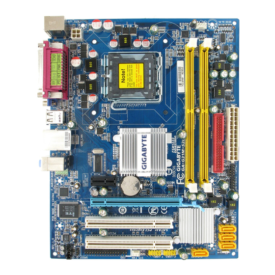
Page 8: Ga-G31M-S2L/Ga-G31M-S2C Motherboard Layout
GA-G31M-S2L/GA-G31M-S2C Motherboard Layout KB_MS ATX_12V R_USB AUDIO F_AUDIO PCIE_1 RTL8111C RTL8102E PCIE_16 IT8718 PCI1 CODEC PCI2 Only for GA-G31M-S2L. Only for GA-G31M-S2C. LGA775 Intel ® MBIOS Intel SYS_FAN F_USB1 F_USB2 - 8 - CPU_FAN ICH7 ® SATAII3 SATAII2 SATAII1 SATAII0... -
Page 9: Block Diagram
PCIe CLK (100 MHz) PCI Express x16 1 PCI Express x1 PCIe CLK (100 MHz) PCI Express Bus PCI Bus 2 PCI PCI CLK (33 MHz) Only for GA-G31M-S2L. Only for GA-G31M-S2C. LGA775 Processor D-Sub Interface Intel ® RJ45 RTL8111C RTL8102E Intel ®... - Page 10 - 10 -...
-
Page 11: Chapter 1 Hardware Installation
Chapter 1 Hardware Installation Installation Precautions The motherboard contains numerous delicate electronic circuits and components which can become damaged as a result of electrostatic discharge (ESD). Prior to installation, carefully read the user's manual and follow these procedures: Prior to installation, do not remove or break motherboard S/N (Serial Number) sticker or •... -
Page 12: Product Specifications
Product Specifications Support for an Intel Intel Intel in the LGA 775 package (Go to GIGABYTE's website for the latest CPU support list.) L2 cache varies with CPU Front Side Bus 1333/1066/800 MHz FSB Chipset North Bridge: Intel South Bridge: Intel Memory 2 x 1.8V DDR2 DIMM sockets supporting up to 4 GB of system memory... - Page 13 Internal Connectors 1 x 24-pin ATX main power connector 1 x 4-pin ATX 12V power connector 1 x floppy disk drive connector 1 x IDE connector 4 x SATA 3Gb/s connectors 1 x CPU fan header 1 x system fan header 1 x front panel header 1 x front panel audio header 1 x CD In connector...
- Page 14 For example, 4 GB of memory size will instead be shown as 3.xx GB during system startup. (Note 2) Available functions in EasyTune may differ by motherboard model. GA-G31M-S2L/S2C Motherboard (Note 2) Windows Vista/XP ®...
-
Page 15: Installing The Cpu And Cpu Cooler
Installing the CPU and CPU Cooler Read the following guidelines before you begin to install the CPU: • Make sure that the motherboard supports the CPU. (Go to GIGABYTE's website for the latest CPU support list.) • Always turn off the computer and unplug the power cord from the power outlet before installing the CPU to prevent hardware damage. - Page 16 Step 5: Once the CPU is properly inserted, replace the load plate and push the CPU socket lever back into its locked position. GA-G31M-S2L/S2C Motherboard Step 2: Lift the metal load plate from the CPU socket. (DO NOT touch socket contacts.)
-
Page 17: Installing The Cpu Cooler
1-3-2 Installing the CPU Cooler Follow the steps below to correctly install the CPU cooler on the motherboard. (The following procedure uses Intel boxed cooler as the example cooler.) ® Step 1: Apply an even and thin layer of thermal grease on the surface of the installed CPU. -
Page 18: Installing The Memory
1. Dual Channel mode cannot be enabled if only one DDR2 memory module is installed. 2. When enabling Dual Channel mode with two memory modules, it is recommended that memory of the same capacity, brand, speed, and chips be used. GA-G31M-S2L/S2C Motherboard - 18 -... -
Page 19: Installing A Memory
1-4-2 Installing a Memory Before installing a memory module , make sure to turn off the computer and unplug the power cord from the power outlet to prevent damage to the memory module. DDR2 DIMMs are not compatible to DDR DIMMs. Be sure to install DDR2 DIMMs on this motherboard. -
Page 20: Installing An Expansion Card
Example: Installing and Removing a PCI Express x16 Graphics Card: • Removing the Card: Gently push back on the lever on the slot and then lift the card straight out from the slot. GA-G31M-S2L/S2C Motherboard PCI Express x16 Slot PCI Slot PCI Express x1 Slot •... -
Page 21: Back Panel Connectors
• When removing the cable, pull it straight out from the connector. Do not rock it side to side to prevent an electrical short inside the cable connector. Only for GA-G31M-S2L. Connection/Speed LED: State... - Page 22 Mic In Jack (Pink) The default Mic in jack. Microphones must be connected to this jack. Refer to the instructions on setting up a 2/4/5.1-channel audio configuration in Chapter 5, "Configuring 2/4/5.1-Channel Audio." Only for GA-G31M-S2C. GA-G31M-S2L/S2C Motherboard Connection/Speed LED: State Description Green...
-
Page 23: Internal Connectors
Internal Connectors ATX_12V CPU_FAN SYS_FAN SATAII0 / 1 / 2 / 3 PWR_LED Read the following guidelines before connecting external devices: • First make sure your devices are compliant with the connectors you wish to connect. • Before installing the devices, be sure to turn off the devices and your computer. Unplug the power cord from the power outlet to prevent damage to the devices. - Page 24 When using a 2x12 power supply, remove the protective cover from the main power connector on the motherboard. Do not insert the power supply cable into pins under the protective cover when using a 2x10 power supply. GA-G31M-S2L/S2C Motherboard ATX_12V ATX : Pin No.
- Page 25 3/4) CPU_FAN/SYS_FAN (Fan Headers) The motherboard has a 4-pin CPU fan header (CPU_FAN) and a 3-pin system fan header (SYS_FAN). Each fan header supplies a +12V power voltage and possesses a foolproof insertion design. When connecting a fan cable, be sure to connect it in the correct orientation. Most fans are designed with color-coded power connector wires.
- Page 26 7) SATAII0/1/2/3 (SATA 3Gb/s Connectors, Controlled by ICH7) The SATA connectors conform to SATA 3Gb/s standard and are compatible with SATA 1.5Gb/s standard. Each SATA connector supports a single SATA device. GA-G31M-S2L/S2C Motherboard SATAII3 SATAII2 SATAII1...
-
Page 27: System Power Led Header
8) PWR_LED (System Power LED Header) This header can be used to connect a system power LED on the chassis to indicate system power status. The LED is on when the system is operating. The LED keeps blinking when the system is in S1 sleep state. -
Page 28: F_Panel Front Panel Header
LED, hard drive activity LED, speaker and etc. When connecting your chassis front panel module to this header, make sure the wire assign- ments and the pin assignments are matched correctly. GA-G31M-S2L/S2C Motherboard Speaker Connector Power Switch... -
Page 29: Cd In Connector
11) F_AUDIO (Front Panel Audio Header) The front panel audio header supports Intel High Definition audio (HD) and AC'97 audio. You may connect your chassis front panel audio module to this header. Make sure the wire assignments of the module connector match the pin assignments of the motherboard header. Incorrect connection between the module connector and the motherboard header will make the device unable to work or even damage it. - Page 30 • Do not plug the IEEE 1394 bracket (2x5-pin) cable into the USB header. • Prior to installing the USB bracket, be sure to turn off your computer and unplug the power cord from the power outlet to prevent damage to the USB bracket. GA-G31M-S2L/S2C Motherboard Pin No. Pin No.
-
Page 31: Chassis Intrusion Header
15) CLR_CMOS (Clearing CMOS Jumper) Use this jumper to clear the CMOS values (e.g. date information and BIOS configurations) and reset the CMOS values to factory defaults. To clear the CMOS values, place a jumper cap on the two pins to temporarily short the two pins or use a metal object like a screwdriver to touch the two pins for a few seconds. - Page 32 GA-G31M-S2L/S2C Motherboard - 32 -...
-
Page 33: Chapter 2 Bios Setup
Chapter 2 BIOS Setup BIOS (Basic Input and Output System) records hardware parameters of the system in the CMOS on the motherboard. Its major functions include conducting the Power-On Self-Test (POST) during system startup, saving system parameters and loading operating system, etc. BIOS includes a BIOS Setup program that allows the user to modify basic system configuration settings or to activate certain system features. -
Page 34: Startup Screen
The following screen may appear when the computer boots. Award Modular BIOS v6.00PG, An Energy Star Ally Copyright (C) 1984-2008, Award Software, Inc. Intel G31 BIOS for G31M-S2L D9a Motherboard Model BIOS Version <DEL>: BIOS Setup/Q-Flash <F9>: XpressRecovery2 <F12>: Boot Menu <End>: Qflash... -
Page 35: The Main Menu
Once you enter the BIOS Setup program, the Main Menu (as shown below) appears on the screen. Use arrow keys to move among the items and press <Enter> to accept or enter a sub-menu. (Sample BIOS Version: GA-G31M-S2L D9a) CMOS Setup Utility-Copyright (C) 1984-2008 Award Software... -
Page 36: Set User Password
(Pressing <F10> can also carry out this task.) Exit Without Saving Abandon all changes and the previous settings remain in effect. Pressing <Y> to the confirmation message will exit BIOS Setup. (Pressing <Esc> can also carry out this task.) GA-G31M-S2L/S2C Motherboard - 36 -... -
Page 37: Standard Cmos Features
Standard CMOS Features CMOS Setup Utility-Copyright (C) 1984-2008 Award Software Date (mm:dd:yy) Time (hh:mm:ss) IDE Channel 0 Master IDE Channel 0 Slave IDE Channel 2 Master IDE Channel 2 Slave IDE Channel 3 Master IDE Channel 3 Slave Drive A Floppy 3 Mode Support Halt On Base Memory... -
Page 38: Floppy 3 Mode Support
Base Memory Also called conventional memory. Typically, 640 KB will be reserved for the MS-DOS operating system. Extended Memory The amount of extended memory. Total Memory The total amount of memory installed on the system. GA-G31M-S2L/S2C Motherboard - 38 -... -
Page 39: Advanced Bios Features
(Default: Disabled) (Note) This item is present only if you install a CPU that supports this feature. For more information about Intel CPUs' unique features, please visit Intel's website. Advanced BIOS Features... -
Page 40: Virtualization Technology
When enabled, the CPU core frequency and voltage will be reduced when the CPU is overheated. (Default: Enabled) CPU EIST Function (Note) Enables or disables Enhanced Intel SpeedStep Technology (EIST). Depending on CPU loading, Intel EIST technology can dynamically and effectively lower the CPU voltage and core frequency ®... -
Page 41: Init Display First
Init Display First Specifies the first initiation of the monitor display from the installed PCI graphics card, PCI Express graphics card or the onboard VGA. Sets the PCI graphics card as the first display. (Default) Onboard Sets the onboard VGA as the first display. Sets PCI Express graphics card as the first display. -
Page 42: Integrated Peripherals
This value is dependent on the On-Chip SATA Mode and PATA IDE Set to settings. When PATA IDE Set to is configured to Ch. 1 Master/Slave, this option will be automatically set to Ch. 0 Master/Slave. Only for GA-G31M-S2L. GA-G31M-S2L/S2C Motherboard Integrated Peripherals... -
Page 43: Usb Controller
This motherboard incorporates cable diagnostic feature designed to detect the status of the attached LAN cable. This feature will detect cabling issue and report the approximate distance to the fault or short. Refer to the following information for diagnosing your LAN cable: Only for GA-G31M-S2L. SMART LAN / Length... -
Page 44: Onboard Serial Port
Options are: 378/IRQ7 (default), 278/IRQ5, 3BC/IRQ7, Disabled. Parallel Port Mode Selects an operating mode for the onboard parallel (LPT) port. Options are: SPP (Standard Parallel Port)(default), EPP (Enhanced Parallel Port), ECP (Extended Capabilities Port), ECP+EPP. GA-G31M-S2L/S2C Motherboard - 44 -... -
Page 45: Power Management Setup
Power Management Setup CMOS Setup Utility-Copyright (C) 1984-2008 Award Software ACPI Suspend Type Soft-Off by PWR-BTTN PME Event Wake Up Power On by Ring Resume by Alarm x Date (of Month) Alarm x Time (hh:mm:ss) Alarm (Note) HPET Support (Note) HPET Mode Power On By Mouse Power On By Keyboard... -
Page 46: Hpet Support
The system is turned on upon the return of the AC power. Memory The system returns to its last known awake state upon the return of the AC power. (Note) Supported on Windows GA-G31M-S2L/S2C Motherboard Vista ; select 64-bit mode when you install 64-bit ® ®... -
Page 47: Pnp/Pci Configurations
PnP/PCI Configurations CMOS Setup Utility-Copyright (C) 1984-2008 Award Software PCI1 IRQ Assignment PCI2 IRQ Assignment : Move Enter: Select F5: Previous Values PCI1 IRQ Assignment Auto 3,4,5,7,9,10,11,12,14,15 PCI2 IRQ Assignment Auto 3,4,5,7,9,10,11,12,14,15 PnP/PCI Configurations [Auto] [Auto] +/-/PU/PD: Value F10: Save F6: Fail-Safe Defaults BIOS auto-assigns IRQ to the first PCI slot. -
Page 48: Pc Health Status
Enables or disables the CPU fan speed control function. Enabled allows the CPU fan to run at different speed according to the CPU temperature. You can adjust the fan speed with EasyTune based on system requirements. If disabled, CPU fan runs at full speed. (Default: Enabled) GA-G31M-S2L/S2C Motherboard PC Health Status [Disabled] 1.268V... -
Page 49: Mb Intelligent Tweaker(M.i.t.)
MB Intelligent Tweaker(M.I.T.) CMOS Setup Utility-Copyright (C) 1984-2008 Award Software Robust Graphics Booster (Note) CPU Clock Ratio CPU Host Clock Control x CPU Host Frequency (Mhz) PCI Express Frequency (Mhz) Performance Enhance System Memory Multiplier (SPD) Memory Frequency (Mhz) 533 High Speed DRAM DLL Settings ******** System Voltage Optimized System Voltage Control... - Page 50 Allows you to set memory voltage. Normal Supplies the memory voltage as required. (Default) +0.1V ~ +0.4V Increases memory voltage by 0.1V to 0.4V at 0.1V increment. Note: Increasing memory voltage may result in damage to the memory. GA-G31M-S2L/S2C Motherboard - 50 -...
- Page 51 FSB OverVoltage Control Allows you to set the Front Side Bus voltage. Normal Supplies the FSB voltage as required. (Default) +0.1V ~ +0.3V Increases FSB voltage by 0.1V to 0.3V at 0.1V increment. CPU Voltage Control Allows you to set the CPU voltage. Normal sets the CPU voltage as required. The adjustable range is dependent on the CPU being installed.
-
Page 52: Load Fail-Safe Defaults
Press <Enter> on this item and then press the <Y> key to load the optimal BIOS default settings. The BIOS defaults settings helps the system to operate in optimum state. Always load the Optimized defaults after updating the BIOS or after clearing the CMOS values. GA-G31M-S2L/S2C Motherboard Load Fail-Safe Defaults Load Optimized Defaults... -
Page 53: Set Supervisor/User Password
2-12 Set Supervisor/User Password CMOS Setup Utility-Copyright (C) 1984-2008 Award Software Standard CMOS Features Advanced BIOS Features Integrated Peripherals Power Management Setup PnP/PCI Configurations PC Health Status MB Intelligent Tweaker(M.I.T.) ESC: Quit F8: Q-Flash Press <Enter> on this item and type the password with up to 8 characters and then press <Enter>. You will be requested to confirm the password. -
Page 54: Save & Exit Setup
Press <Enter> on this item and press the <Y> key. This exits the BIOS Setup without saving the changes made in BIOS Setup to the CMOS. Press <N> or <Esc> to return to the BIOS Setup Main Menu. GA-G31M-S2L/S2C Motherboard Load Fail-Safe Defaults... -
Page 55: Chapter 3 Drivers Installation
Chapter 3 Drivers Installation • Before installing the drivers, first install the operating system. (The following instructions use Windows XP as the example operating system.) • After installing the operating system, insert the motherboard driver disk into your optional drive. The driver Autorun screen is automatically displayed which looks like that shown in the screen shot below. -
Page 56: Software Applications
This page displays all the tools and applications that GIGABYTE develops and some free software. You may press the Install button following an item to install it. Driver CD Information This page provides information about the drivers, applications and tools in this driver disk. GA-G31M-S2L/S2C Motherboard - 56 -... -
Page 57: Hardware Information
Hardware Information This page provides information about the hardware devices on this motherboard. Contact Us Check the contacts information of the GIGABYTE headquarter in Taiwan and the overseas branch offices on the last page of this manual. - 57 - Drivers Installation... - Page 58 GA-G31M-S2L/S2C Motherboard - 58 -...
-
Page 59: Chapter 4 Unique Features
• The amount of data and hard drive access speed may affect the speed at which the data is backed up/restored. • It takes longer to back up a hard drive than to restore it. System Requirements: • Intel platform • At least 64 MB of system memory • VESA compatible graphics card • Windows XP with SP1 or later ®... -
Page 60: Installation And Configuration
Recovery2 (10 GB or more is recommended; actual size requirements vary, depending on the amount of data) (Figure 2). Figure 1 3. Select a file system (for example, NTFS) and begin the installation of the operating system (Figure 3). Figure 3 GA-G31M-S2L/S2C Motherboard Figure 2 - 60 -... - Page 61 4. After the operating system is installed, right-click the My Computer icon on your desktop and select Manage (Figure 4). Go to Computer Management to check disk allocation. Xpress Recovery2 will save the backup file to the unallocated space (black stripe along the top)(Figure 5). Please note that if there is no enough unallocated space, Xpress Recovery2 cannot save the backup file.
- Page 62 <F9> during the POST (Figure 9). Award Modular BIOS v6.00PG, An Energy Star Ally Copyright (C) 1984-2008, Award Software, Inc. Intel G31 BIOS for G31M-S2L D9a <DEL>: BIOS Setup/Q-Flash <F9>: XpressRecovery2 <F12>: Boot Menu <End>: Qflash 08/21/2007-G31-ICH7-6A79OG0VC-00 C. Using the Backup Function in Xpress Recovery2 1.
- Page 63 D. Using the Restore Function in Xpress Recovery2 Select RESTORE to restore the backup to your hard drive in case the system breaks down. The RESTORE option will not be present if no backup is created before (Figure 13, 14). Figure 13 E.
-
Page 64: Bios Update Utilities
Q-Flash. Award Modular BIOS v6.00PG, An Energy Star Ally Copyright (C) 1984-2008, Award Software, Inc. Intel G31 BIOS for G31M-S2L D9a <DEL>: BIOS Setup/Q-Flash <F9>: XpressRecovery2 <F12>: Boot Menu <End>: Qflash 08/21/2007-G31-ICH7-6A79OG0VC-00 Because BIOS flashing is potentially risky, please do it with caution. Inadequate BIOS flashing may result in system malfunction. - Page 65 B. Updating the BIOS When updating the BIOS, choose the location where the BIOS file is saved. The follow procedure assumes that you save the BIOS file to a floppy disk. Step 1: 1. Insert the floppy disk containing the BIOS file into the floppy disk drive. In the main menu of Q- Flash, use the up or down arrow key to select Update BIOS from Drive and press <Enter>.
- Page 66 F8: Q-Flash Step 6: Select Save & Exit Setup and then press <Y> to save settings to CMOS and exit BIOS Setup. The procedure is complete after the system restarts. GA-G31M-S2L/S2C Motherboard Load Fail-Safe Defaults Load Optimized Defaults Set Supervisor Password...
-
Page 67: Updating The Bios With The @Bios Utility
4-2-2 Updating the BIOS with the @BIOS Utility A. Before You Begin: 1. In Windows, close all applications and TSR (Terminate and Stay Resident) programs. This helps prevent unexpected failures when performing a BIOS update. 2. During the BIOS update process, ensure the Internet connection is stable and do NOT interrupt the Internet connection (for example, avoid a power loss or switching off the Internet). - Page 68 Step 4: As the system boots, press <Delete> to enter the BIOS Setup program. Select Load Optimized Defaults and press <Enter> to load BIOS defaults. GA-G31M-S2L/S2C Motherboard Step 3: First make sure the model name on the screen is correct, then click OK.
-
Page 69: Easytune 5 Pro
EasyTune 5 Pro EasyTune 5 Pro, an easy-to-use and convenient system overclocking and management tool, lets you do overclock and overvoltage in Windows environment, eliminating the need to enter the BIOS Setup program. EasyTune 5 Pro provides the following functions C.I.A./M.I.B. - Page 70 GA-G31M-S2L/S2C Motherboard - 70 -...
-
Page 71: Chapter 5 Appendix
Chapter 5 Appendix Configuring Audio Input and Output 5-1-1 Configuring 2/4/5.1-Channel Audio The motherboard provides three audio jacks on the back panel which support 2/4/5.1-channel to the right shows the default audio jack assignments. Audio signals will be present on both of the front and back panel audio connections simultaneously. If you want to mute the back panel audio (only supported when using an HD front panel audio module), refer to instructions on page 73. - Page 72 Everytime you connect an audio device to an audio jack, the Connected device box appears. Select the device according to the type of device you connect. Then click OK to complete the configuration. GA-G31M-S2L/S2C Motherboard 2-Channel Speakers: 4-Channel Speakers: 5.1-Channel Speakers:...
- Page 73 B. Configuring Sound Effect: You may configure an audio environment on the Sound Effect tab. C. Activating an AC'97 Front Panel Audio Module: If your chassis provides an AC'97 front panel audio module, to activate the AC'97 functionality, click the tool icon on the Audio I/O tab.
-
Page 74: Installing The S/Pdifout Cable (Optional)
Install the S/PDIF in and out cable first if you want to output S/PDIF digital audio signals to an external decoder. A. Installing the S/PDIF Out Cable: GA-G31M-S2L/S2C Motherboard Step 1: First, attach the connector at the end of the cable to the SPDIF_O header on your motherboard. -
Page 75: Configuring S/Pdif Out
S/PDIF Coaxial Cable S/PDIF Optical Cable B. Configuring S/PDIF out: Click the tool icon in the DIGITAL section. In the S/PDIF Settings dialog box, select an output sam- pling rate and select (or disable) the output source. Click OK to complete the configuration. (Note) The actual locations of the SPDIF In and SPDIF Out connectors may differ by model. -
Page 76: Configuring Microphone Recording
Note: The microphone functions on the front panel and back panel cannot be used at the same time. Step 3: Locate the Volume icon in your system tray and click it to open the volume control panel GA-G31M-S2L/S2C Motherboard - 76 -... - Page 77 Step 4: To hear the sound being recorded during the record- ing process when using the microphone function on the front panel, do not select the Mute check box under Front Pink In or Front Green In in Master Volume. It is recommended that you set the volume at a middle level.
-
Page 78: Using The Sound Recorder
3. To play a sound file, click the Play button 4. To stop playing, click the Stop button 5. You may use the Fast Forward button move to the beginning of a file or the Fast Back- ward button to the end. GA-G31M-S2L/S2C Motherboard - 78 -... -
Page 79: Faqs
Troubleshooting 5-2-1 Frequently Asked Questions To read more FAQs for your motherboard, please go to the Support\Motherboard\FAQ page on GIGABYTE's website. Q: In the BIOS Setup program, why are some BIOS options missing? A: Some advanced options are hidden in the BIOS Setup program. Press <Delete> to enter BIOS Setup during the POST. -
Page 80: Troubleshooting Procedure
Turn on the power to start the computer. Press <Delete> to enter BIOS Setup. Select "Load Fail-Safe Defaults" (or "Load Optimized Defaults"). Select "Save & Exit Setup" to save changes and exit BIOS Setup. GA-G31M-S2L/S2C Motherboard START (Continued...) - 80 - Isolate the short circuit. - Page 81 When the computer is turned on, is the CPU cooler running? Check if there is display on your monitor. Turn off the computer. Plugg in the keyboard and mouse and restart the computer. Check if the keyboard is working properly. Press <Delete>...
-
Page 82: Regulatory Statements
If you need further assistance in recycling, reusing in your "end of life" product, you may contact us at the Customer Care number listed in your product's user's manual and we will be glad to help you with your effort. GA-G31M-S2L/S2C Motherboard - 82 -... - Page 83 Finally, we suggest that you practice other environmentally friendly actions by understanding and using the energy-saving features of this product (where applicable), recycling the inner and outer packaging (including shipping containers) this product was delivered in, and by disposing of or recycling used batteries properly.
- Page 84 GA-G31M-S2L/S2C Motherboard - 84 -...
- Page 85 - 85 - Appendix...
- Page 86 GA-G31M-S2L/S2C Motherboard - 86 -...
- Page 87 Contact Us GIGA-BYTE TECHNOLOGY CO., LTD. Address: No.6, Bau Chiang Road, Hsin-Tien, Taipei 231, Taiwan TEL: +886-2-8912-4000 FAX: +886-2-8912-4003 Tech. and Non-Tech. Support (Sales/Marketing) : http://ggts.gigabyte.com.tw WEB address (English): http://www.gigabyte.com.tw WEB address (Chinese): http://www.gigabyte.tw G.B.T. INC. - U.S.A. TEL: +1-626-854-9338 FAX: +1-626-854-9339 Tech.
- Page 88 WEB address : http://www.giga-byte.it Spain WEB address : http://www.giga-byte.es Greece WEB address : http://www.giga-byte.gr Czech Republic WEB address : http://www.gigabyte.cz GIGABYTE Global Service System GA-G31M-S2L/S2C Motherboard Hungary WEB address : http://www.giga-byte.hu Turkey WEB address : http://www.gigabyte.com.tr Russia WEB address : http://www.gigabyte.ru Poland WEB address : http://www.gigabyte.pl...
Need help?
Do you have a question about the GA-G31M-S2L and is the answer not in the manual?
Questions and answers