Table of Contents
Advertisement
Advertisement
Table of Contents

Related Manuals for Riello VSD 1100


Summary of Contents for Riello VSD 1100
- Page 2 NTRODUCTION Congratulations on purchasing a UPS Vision Dual product and welcome to Riello UPS! To use the support service offered by Riello UPS, visit the site www.riello-ups.com Our Company is a specialist in the design, development and manufacturing of uninterruptible power supplies (UPS).
-
Page 3: Table Of Contents
ONTENTS PRESENTATION UPS V IEWS RONT VIEW EAR VIEW ISPLAY PANEL VIEW ATTERY ACCESSORY NOT SUPPLIED WITH THE UPS EAR VIEW INSTALLATION NITIAL CONTENT CHECK NSTALLATION ENVIRONMENT ATTERY OX INSTALLATION ... - Page 4 ATTERY PACK REPLACEMENT TROUBLESHOOTING LARM CODES AULT TECHNICAL DATA ...
-
Page 5: Presentation
PRESENTATION The VISION DUAL series is the ideal solution for high end users who require high security and versatility from their power systems. The VISION DUAL is the best protection system available for network devices, servers and conventional storage systems. The VISION DUAL series is a range of UPS which utilises the very latest Line Interactive technology and sinusoidal output voltage waveforms. -
Page 6: Ups Views
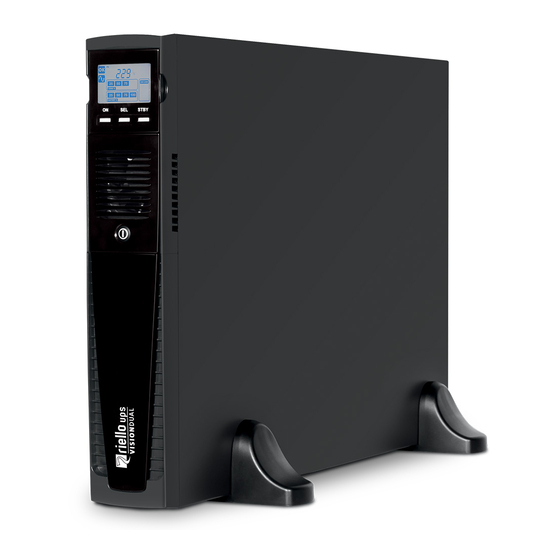
UPS V IEWS RONT VIEW Extractable/rotatable display plate Removable front panel Release slits Battery pack connector ON/OFF Switch Battery pack retention panel... -
Page 7: Rear View
EAR VIEW Model 1100VA / 1500VA Model 2200VA / 3000VA Communication port RS232 Battery expansion connector (optional) USB communication port IEC 10A output socket IEC 16A output socket IEC 16A input plug Communication Card Slots IEC 10A input plug Cooling fans Circuit breaker Remote control terminal board... -
Page 8: Display Panel View
ISPLAY PANEL VIEW “SEL” button (Select) Load level indicator “ON” button Configuration area “STAND-BY” button Maintenance request Regular operation Timer Mains operation Measurement display area Battery operation Stand-by / alarm AVR active EnergyShare Battery charge indicator... -
Page 9: Battery Box ( Accessory Not Supplied With The Ups )
ATTERY ACCESSORY NOT SUPPLIED WITH THE UPS The BATTERY BOX is an optional accessory for this range of UPS (same dimensions and aesthetic appearance). The BATTERY BOX contains batteries which allow the operating time of the uninterruptible power supplies to be increased during extended blackouts. -
Page 10: Installation
INSTALLATION NITIAL CONTENT CHECK After opening the packaging , it is first necessary to check the contents. he package must contain: Support feet Schuko power cable - IEC 10A 2 IEC 10A connection cables (IEC 16A only for models 2200/3000VA) USB cable RS232 cable User manual CD + Safety manual... -
Page 11: Installation Environment
It is not possible to co nnect more than one UPS to a single battery box, or to several Battery Boxes connected in a series. To check the availability of a new version of the latest software, visit the website www.riello-ups.com. -
Page 12: Tower Version
OWER VERSION T his chapter describes the steps for preparing the UPS and battery box for tower version use. ATTENTION: For your safety and that of the product, you must carefully follow the instructions given here below. BEFORE YOU CARRY OUT THE FOLLOWING SEQUENCE OF OPERATIONS, MAKE SURE THAT THE UPS IS COMPLETELY SWITCHED OFF AND NOT CONNECTED TO THE MAINS POWER SUPPLY OR TO ANY LOAD Once removed from the packaging, the UPS is already preset for installation in... -
Page 13: Tower Version With Battery Box
OWER VERSION WITH BATTERY BOX BEFORE CARRING OUT THE FOLLOWING SEQUENCE OF OPERATIONS, ENSURE THAT: • THE UPS IS COMPLETELY SWITCHED OFF AND NOT CONNECTED TO THE MAINS POWER SUPPLY OR TO ANY LOAD. • THE BATTERY BOX IS DISCONNECTED FROM THE UPS, FROM ANY OTHER BATTERY BOXES AND WITH THE BATTERY ISOLATOR OPEN For the battery box version each foot is composed of three parts: two supports and an extension. -
Page 14: Rack Version
ACK VERSION The sequence of operations to be followed in order to transform the UPS or battery box into rack version are described elow. BEFORE CARRING OUT THE FOLLOWING SEQUENCE OF OPERATIONS, ENSURE THAT: • THE UPS IS COMPLETELY SWITCHED OFF AND NOT CONNECTED TO THE MAINS POWER SUPPLY OR TO ANY LOAD. -
Page 15: Use
6) Check which operating mode is set on the display and, if necessary, see the “Configuring operating modes” paragraph to set the required mode. For advanced UPS configurations execute the software UPSTools which can be downloaded from the web site www.riello-ups.com. WITCHING ON FROM THE MAINS 1) Press the “ON”... -
Page 16: Display Panel Messages
ISPLAY PANEL MESSAGES This chapter describes, in detail, the various information that can be displayed on the LCD. STATUS MESSAGES ICON STATUS DESCRIPTION Fixed Indicates a fault Flashing The UPS is in stand-by mode Fixed Indicates regular operation Flashing The UPS is in “Battery swap” mode Fixed The UPS is operating from the mains The UPS is operating from the battery. -
Page 17: Measurement Display Area
EASUREMENT DISPLAY AREA The front panel can be used to display important UPS operating information. When the UPS is switched-on, the display shows the main voltage value. To display a different measurement, press the “SEL” button repeatedly until the desired measurement appears. In the event of a fault/alarm (FAULT) or a lock (LOCK), the display will automatically show the type and code of the corresponding alarm. -
Page 18: Configuring The Operating Mode
ONFIGURING THE OPERATING MODE The area of the display shown in the figure displays the active operating mode and allows the user to choose other modes directly from the display panel. HOW TO PROCEED: • To access the configuration area, hold down the “SEL” button for at least 3 seconds. •... - Page 19 REMOTE CONTROL TERMINAL BOARD The remote control terminal allows for implementation of the REPO function (Remote Emergency Power Off) and to remotely switch on/off the UPS. The UPS is provided by the manufacturer with the REPO terminals short-circuited. For installation remove the short circuit and connect to the device's normally closed contact.
-
Page 20: Software
2) Download the software from the web site www.riello-ups.com selecting the specific operating system. 3) Follow the installation program instructions. 4) For more detailed information please read the user manual which can be downloaded from www.riello- ups.com. ONFIGURATION SOFTWARE The UPStools software allows the configuration and full display of the status of the UPS via USB or RS232. -
Page 21: Ups Configuration
CONFIGURATION The table below illustrates all the possible configurations available to the user in order to best adapt the UPS for individual requirements. It is possible to perform these operations using the UPStools software. FUNCTION DESCRIPTION DEFAULT POSSIBLE CONFIGURATIONS • 50 Hz Output Selects the nominal output •... -
Page 22: Communication Ports
Serial duplicator • Ethernet network card with TCP/IP, HTTP and SNMP protocols • JBUS / MODBUS protocol converter card • PROFIBUS protocol converter card • Card with relay isolated contacts To check the availability of other accessories, visit the website www.riello-ups.com. -
Page 23: B Attery Pack Replacement
ATTERY PACK REPLACEMENT The UPS is also equipped with a dedicated battery pack that allows for easy replacement of batteries (hot swap) in omplete safety, thanks to the protected connection system. • WHEN THE BATTERY PACK IS DISCONNECTED, THE LOADS CONNECTED TO THE UPS ARE NOT PROTECTED IN THE EVENT OF A MAINS FAILURE. - Page 24 Remove the battery pack's retention panel carrying out the operations shown in the figure below. Slip off the battery pack pulling it towards the outside, as shown in the figure below. Be careful when extracting and lifting up the battery pack as it is heavy. ATTENTION: the new battery pack must contain the same number and type of batteries (see the label located on the battery pack near the connector).
-
Page 25: Troubleshooting
TROUBLESHOOTING Irregular UPS operation is not always an indication of a fault, and can be due to minor or easy-to-resolve issues It is therefore advisable to consult the table below as it contains information which is useful for solving the most common UPS problems. - Page 26 The UPS in case of a permanent failure will be not able to supply the load. To ensure total protection of your equipment we suggest you install an ATS device (Automatic Transfer Switch) or an external automatic by-pass. For more information visit www.riello-ups.com...
-
Page 27: A Larm Codes
LARM CODES Using a sophisticated self-diagnosis system, the UPS is able to check its own status for any anomalies and/or faults which may occur during normal operation and display them on the display panel. If there is a problem, the UPS signals he event by showing the code and the type of active alarm on the display (FAULT and/or LOCK). - Page 28 Active commands: Indicates the presence of an active remote command. CODICE DESCRIZIONE Remote control 1 (Switch On/Off) Remote control 2 (Load supplied by the mains) Remote control 3 (Switch On/Off) Battery test in progress LOCK alerts are normally preceded by an alarm signal and their scale leads to the powering-off of the inverter with the load being powered by the bypass line (this procedure is excluded for locks due to serious, persistent overloads and short circuits).
-
Page 29: Technical Data
28 / 15.5 31.5 / 16.5 For additional details regarding technical data refer to website www.riello-ups.com @ rated load, rated voltage of 220 Vac, battery charging To maintain output voltage within the accuracy range specified, recalibration may be necessary after a long period of operation 20 - 25 °C for longer battery life... - Page 30 BATTERY BOX MODELS JSDH072-NPA- JSDH072-NPM- Battery rated voltage [Vdc] 72Vdc Dimensions W x D x H [mm] 87 x 625 x 450 Weight [Kg] The "-" symbol replaces an alphanumeric code for internal use If the UPS is connected to a battery box, the maximum active power is derated from PF 0,9 to PF 0,8.
Need help?
Do you have a question about the VSD 1100 and is the answer not in the manual?
Questions and answers