Integra DTR-8.8 Instruction Manual
Integra av receiver instruction manual
Hide thumbs
Also See for DTR-8.8:
- Instruction manual (144 pages) ,
- Service manual (314 pages) ,
- Service manual (314 pages)
Table of Contents
Advertisement
Quick Links
Advertisement
Table of Contents

Related Manuals for Integra DTR-8.8


Summary of Contents for Integra DTR-8.8
- Page 1 AV Receiver DTR-8.8 Instruction Manual...
-
Page 2: Important Safety Instructions
Thank you for purchasing an Integra AV Receiver. Please read this manual thoroughly before making connections and plugging in the unit. Following the instructions in this manual will enable you to obtain optimum performance and listening enjoyment from your new AV Receiver. - Page 3 Precautions 1. Recording Copyright—Unless it’s for personal use only, recording copyrighted material is illegal with- out the permission of the copyright holder. 2. AC Fuse—The AC fuse inside the unit is not user- serviceable. If you cannot turn on the unit, contact the dealer from whom you purchased this unit.
-
Page 4: Table Of Contents
Connecting the Power Cords of Other Components (North American model only) ... 44 Connecting an External Controller ... 44 Connecting Integra/Onkyo Connecting the Power Cord ... 45 Turning On the AV Receiver ... 46 Turning On and Standby ... 46 First Time Setup ... - Page 5 Contents—Continued Advanced Setup ... 101 Speaker Setup ...101 Source Setup ...108 Miscellaneous Setup ...111 Hardware Setup ...113 Lock Setup ...115 Net/USB ... 116 About Net/USB ...116 Connecting the AV Receiver ...117 Playing Music Files on a Server ...118 ® Windows Media Player 11 Setup ...119 Playing Music Files on a USB Device ...119 Listening to Internet Radio ...121...
-
Page 6: Features
Features Amplifier • 7-channel amplifier • 140 watts minimum continuous power per channel, 8 ohm loads, 2 channels driven from 20 Hz to 20 kHz, with a maximum total harmonic distortion of 0.05% (FTC) • Linear Optimum Gain Volume Circuitry •... -
Page 7: Supplied Accessories
Features—Continued ® XM Ready is a trademark of XM Satellite Radio Inc. ©2005 XM Satellite Radio Inc. All rights reserved. ©2005 SIRIUS Satellite Radio Inc. “SIRIUS,” SiriusConnect, the SIRIUS dog logo, channel names and logos are trademarks of SIRIUS Satellite Radio Inc. Available only in the contiguous United States (excluding Alaska and Hawaii) and Canada. -
Page 8: Multiroom Capability
Multiroom Capability You can use three speaker systems with this AV receiver—a surround-sound speaker system (up to 7.1 channels) in your main listening room, a stereo speaker system in a second room, or Zone 2, as we call it, and another stereo speaker system in a third room that we call Zone 3. -
Page 9: Getting To Know The Av Receiver
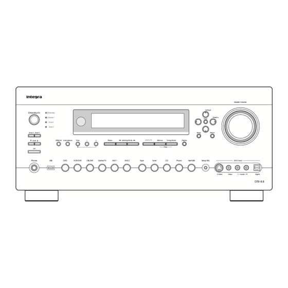
Getting to Know the AV Receiver Front Panel North American model Other models The actual front panel has various logos printed on it. They are not shown here for clarity. The page numbers in parentheses show where you can find the main explanation for each item. Standby/On button (46) Sets the AV receiver to On or Standby. - Page 10 Getting to Know the AV Receiver—Continued Zone 3 indicator (128) Flashes when Zone 3 is being set. Lights up when Zone 3 is on. Remote-control sensor (15) Receives control signals from the remote controller. Stereo button (88) Selects the Stereo listening mode. Listening Mode [ Select the listening modes.
-
Page 11: Display
Getting to Know the AV Receiver—Continued Display For detailed information, see the pages in parentheses. Speaker/channel indicators Indicate the speaker configuration and channels used by the current input source. – : A box is displayed for each speaker that’s set in the Speaker Configuration. -
Page 12: Rear Panel
Getting to Know the AV Receiver—Continued Rear Panel North American model RS232 IN 4 COMPONENT VIDEO ASSIGNABLE MONITOR IN 3 IN 2 IN 1(DVD) OUT 1 REMOTE CONTROL DIGITAL ASSIGNABLE COAXIAL IN 1 (DVD) IN 2 (VCR/DVR) IN 3 (CBL/SAT) OPTICAL PHONO IN 1... - Page 13 Getting to Know the AV Receiver—Continued COMPONENT VIDEO IN 1, 2, and 3 These RCA component video inputs are for con- necting components with a component video output, such as a DVD player, DVD recorder, or DVR (dig- ital video recorder). They’re assignable, which means you can assign each one to an input selector to suit your setup.
- Page 14 Getting to Know the AV Receiver—Continued CBL/SAT IN A cable or satellite receiver can be connected here. There’s S-Video and composite video input jacks for connecting the video signal. VCR/DVR IN/OUT A video component, such as a VCR or DVR, can be connected here for recording and playback.
-
Page 15: Remote Controller
Remote Controller Installing the Batteries To open the battery compartment, press the small hollow and slide open the cover. Insert the three supplied batteries (AA/R6) in accordance with the polarity diagram inside the battery compartment. Slide the cover shut. Notes: •... -
Page 16: About The Remote Controller Modes
(see page 132). ■ CD/CDR/MD Mode By default, you can control an Integra/Onkyo CD player in this mode. By entering the appropriate remote control code, you can control a CD player, MD recorder, or CD recorder made by another manufacturer (see page 132). - Page 17 Remote Controller—Continued For detailed information, see the pages in parentheses. Standby button (46) Sets the AV receiver to Standby. On button (46) Turns on the AV receiver. Input Selector buttons (62) Used to select the input source. Macro buttons (136) Used with the Macro function.
-
Page 18: Dvd Mode
Remote Controller—Continued DVD Mode To set the remote controller to DVD mode, press the [DVD] Remote Mode button. Standby AUX 1 AUX 2 Game Tape Tuner Phono Net/USB D.TUN Clear --/--- 10 Input Selector Macro Remote Mode CDR/MD/Dock Cable Net/USB Dimmer Enter Disc... -
Page 19: Cd/Md/Cdr Modes
Remote Controller—Continued CD/MD/CDR Modes To control an Integra/Onkyo CD player, MD recorder, or CD recorder, or a CD or MD player/recorder made by another manufacturer, press the [CD] Remote Mode button to select the CD/MD/CDR remote controller mode. In order to control an Onkyo MD recorder or CD recorder, or a component made by another manufacturer, you must first enter the appropriate remote control code... -
Page 20: Dock Mode
Remote Controller—Continued Dock Mode Dock mode is for controlling an Apple iPod in an Onkyo RI Dock. To control an RI Dock, press the [CD] REMOTE MODE button to select the Dock remote controller mode. In order to control an RI Dock, you must first enter the appropriate remote control code (see page 132). -
Page 21: Net/Usb Mode
Remote Controller—Continued Net/USB Mode Net/USB mode is for playing music files on a networked computer, media server, or USB mass storage device, or for listening to Internet radio. To set the remote controller to Net/USB mode, press the [Net/USB] Remote Mode button. Standby Input TV CH... -
Page 22: Connecting Your Speakers
Connecting Your Speakers Enjoying Home Theater Thanks to the AV receiver’s superb capabilities, you can enjoy surround sound with a real sense of movement in your own home—just like being in a movie theater or concert hall. You can enjoy DVDs featuring Dolby Digital or DTS. With analog or digital TV, you can enjoy Dolby Pro Logic IIx, DTS Neo:6, or Onkyo’s original DSP listening modes. -
Page 23: Connecting Your Speakers
Connecting Your Speakers—Continued Connecting Your Speakers Speaker Configuration For the best surround-sound experience, you should con- nect seven speakers and a powered subwoofer. The following table shows which channels you should use based on the number of speakers you have. Number of speakers: ✓... -
Page 24: Speaker Connection Precautions
Connecting Your Speakers—Continued Speaker Connection Precautions Read the following before connecting your speakers: • You can connect speakers with an impedance of between 4 and 16 ohms. If the impedance of any of the connected speakers is 4 ohms or more but less than 6, be sure to set the speaker impedance to 4 ohms (see page 47). -
Page 25: Bi-Amping The Front Speakers
Connecting Your Speakers—Continued Bi-amping the Front Speakers The FRONT L/R and SURR BACK L/R terminal posts can be used with front speakers and surround back speakers respectively, or bi-amped to provide separate tweeter and woofer feeds for a pair of front speakers that support bi-amping, providing improved bass and treble performance. -
Page 26: Bridging The Front Speakers
Connecting Your Speakers—Continued Bridging the Front Speakers The FRONT L/R and SURR BACK L/R terminal posts can be used with front speakers and surround back speakers respectively, or bridged together to provide almost double the output power for the front speakers. •... -
Page 27: Connecting Antennas
Connecting Antennas This section explains how to connect the supplied indoor FM antenna and AM loop antenna, and how to connect commercially available outdoor FM and AM antennas. The AV receiver won’t pick up any radio signals without any antenna connected, so you must connect the antenna to use the tuner. -
Page 28: Connecting An Outdoor Fm Antenna
Connecting Antennas—Continued ■ Other Models Push Insert wire Once your AV receiver is ready for use, you’ll need to tune into an AM radio station and adjust the position of the AM antenna to achieve the best possible reception. Keep the antenna as far away as possible from your AV receiver, TV, speaker cables, and power cords. -
Page 29: Connecting Your Components
Connecting Your Components About AV Connections • Before making any AV connections, read the manuals supplied with your other AV components. • Don’t connect the power cord until you’ve completed and double-checked all AV connections. Optical Digital Jacks The AV receiver’s optical digital jacks have shutter-type covers that open when an optical plug is inserted and close when it’s removed. -
Page 30: Connecting Audio And Video Signals To The Avreceiver
Connecting Your Components—Continued Connecting Audio and Video Signals to the AV Receiver By connecting both the audio and video outputs of your DVD player and other AV components to the AV receiver, you can switch the audio and video signals simultaneously simply by changing the input source on the AV receiver. : Signal Flow Video Audio... - Page 31 Connecting Your Components—Continued ■ HDMI Monitor Setting Set to No With the HDMI Monitor setting set to No (see page 48), video input signals flow through the AV receiver as shown, with composite video and S-Video sources being upconverted for the component video output.
-
Page 32: Connecting A Tv Or Projector
Connecting Your Components—Continued Connecting a TV or Projector Step 1: Video Connection Choose a video connection that matches your TV ( , Step 2: Audio Connection Choose an audio connection that matches your TV ( , • With connection , you can listen to and record audio from your TV or listen in Zone 2 or Zone 3. •... -
Page 33: Connecting A Dvd Player
Connecting Your Components—Continued Connecting a DVD player Step 1: Video Connection Choose a video connection that matches your DVD player ( , If you use connection , you must connect the AV receiver to your TV with the same type of connection. Step 2: Audio Connection Choose an audio connection that matches your DVD player ( , •... - Page 34 Connecting Your Components—Continued Hooking Up the Multichannel Input If your DVD player supports multichannel audio formats such as DVD-Audio and SACD, and it has a multichannel analog audio output, you can connect it to the AV receiver’s multichannel input. Use a multichannel analog audio cable, or several normal audio cables, to connect the AV receiver’s MULTI CH FRONT L/R, CENTER, SURR L/R, SURR BACK L/R, and SUBWOOFER jacks to the 7.1-channel analog audio output on your DVD player.
-
Page 35: Connecting A Vcr Or Dvr For Playback
Connecting Your Components—Continued Connecting a VCR or DVR for Playback With this hookup, you can use the tuner in your VCR or DVR to listen to your favorite TV programs Hint! via the AV receiver, which is useful if your TV has no audio outputs. Step 1: Video Connection Choose a video connection that matches your VCR or DVR ( , connection... -
Page 36: Connecting A Vcr Or Dvr For Recording
Connecting Your Components—Continued Connecting a VCR or DVR for Recording Step 1: Video Connection Choose a video connection that matches your VCR or DVR ( source to be recorded must be connected to the AV receiver via the same type of connection. Step 2: Audio Connection Choose an audio connection that matches your VCR or DVR ( Connection... -
Page 37: Connecting A Satellite, Cable, Or Terrestrial Set-Top Box Or Other Video Source
Connecting Your Components—Continued Connecting a Satellite, Cable, or Terrestrial Set-top box or Other Video Source With this hookup, you can use your satellite or cable receiver to listen to your favorite TV programs Hint! via the AV receiver, which is useful if your TV has no audio outputs. Step 1: Video Connection Choose a video connection that matches the video source ( , If you use connection... -
Page 38: Connecting Components With Hdmi
Connecting Your Components—Continued Connecting Components with HDMI About HDMI Designed to meet the increased demands of digital TV, HDMI (High Definition Multimedia Interface) is a new digital interface standard for connecting TVs, projectors, DVD players, set-top boxes, and other video components. Until now, several separate video and audio cables have been required to connect AV components. -
Page 39: Making Hdmi Connections
Connecting Your Components—Continued Making HDMI Connections Step 1: Use HDMI cables to connect the AV receiver’s HDMI jacks to your HDMI-compatible DVD player, TV, projector, and so on. Step 2: Assign each HDMI IN to an input selector. See “HDMI Input Setup” on page 50. ■... -
Page 40: Connecting A Game Console
Connecting Your Components—Continued Connecting a Game Console Step 1: Video Connection Choose a video connection that matches your game console ( , If you use connection , you must connect the AV receiver to your TV with the same type of connection. Step 2: Audio Connection Choose an audio connection that matches your DVD player ( , •... -
Page 41: Connecting A Camcorder Or Other Av Component
Connecting Your Components—Continued Connecting a Camcorder or Other AV Component Step 1: Video Connection Choose a video connection that matches your camcorder ( Step 2: Audio Connection Choose an audio connection that matches your camcorder ( Connection AV receiver AUX 2 Input S Video AUX 2 Input Video AUX 2 Input Audio-L/R AUX 2 Input Digital... -
Page 42: Connecting A Cd Player
Connecting Your Components—Continued Connecting a CD Player Step 1: Choose a connection that matches your CD player ( , COAXIAL IN 2 OPTICAL IN 2 Connect one or the other • With connection , you can listen to and record audio from the CD player or listen in Zone 2 or Zone 3. •... -
Page 43: Connecting A Cassette, Cdr, Minidisc, Or Dat Recorder
Connecting Your Components—Continued Connecting a Cassette, CDR, MiniDisc, or DAT Recorder Step 1: Choose a connection that matches your recorder ( , COAXIAL IN 2 OPTICAL IN 2 OPTICAL Connect one COAXIAL or the other • With connection , you can play and record or listen in Zone 2 or Zone 3. •... -
Page 44: Connecting An Ri Dock
AV receiver is set to On or Standby, or Ready mode in this case, so any components connected to them cannot be turned on or off automatically. • Integra/Onkyo components connected via the AV receiver. Connecting an External Controller The AV receiver can be controlled externally by connecting an external controller. -
Page 45: Connecting Integra/Onkyo Components
Connecting Your Components—Continued Connecting Integra/Onkyo Step 1: Make sure that each Integra/Onkyo component is connected to the AV receiver with an analog audio cable (RCA). Step 2: Make the necessary connections (see illustration below). Step 3: If you’re using an MD, CDR, or RI DOCK component, change the Input Display (see page 52). -
Page 46: Turning On The Av Receiver
Turning On the AV Receiver • North American model Standby/On Standby indicator Turning On and Standby Remote AV receiver controller Receiver Up and Running in a Few Easy Steps To get your system up and running with the minimum of fuss, here’s a few pointers to help you configure the AV receiver before you use it for the very first time. -
Page 47: First Time Setup
First Time Setup This section explains the settings that you need to make before using the AV receiver for the very first time. Speaker Settings TV CH Game AUX 1 AUX 2 If you change these settings, you must run the auto- Tape Tuner matic speaker setup again (see page 55). -
Page 48: Hdmi Monitor Setup
First Time Setup—Continued HDMI Monitor Setup Standby AUX 1 Game Tape Tuner Phono Net/USB --/--- 10 Input Selector Macro Remote Mode CDR/MD/Dock Cable Dimmer 2, 3 Enter Disc Album 1, 6 Prev Display Playlist Listening Mode Stereo Surround Repeat Audio Direct If you connect your TV to a video output other than the HDMI OUT MAIN or HDMI OUT SUB, set the HDMI... - Page 49 First Time Setup—Continued Use the Up and Down [ buttons to select “Resolution,” and use the Left and Right Enter ] buttons to select: Through: Select this to pass video through the AV receiver at the same resolution and with no conversion (default).
-
Page 50: Hdmi Input Setup
First Time Setup—Continued HDMI Input Setup Remote Mode CDR/MD/Dock Cable Dimmer 2, 3 Enter Disc Album 1, 5 Prev Display If you connect a video component to an HDMI IN, you must assign that input to an input selector. For example, if you connect your DVD player to HDMI IN 1, you must assign HDMI IN 1 to the DVD input selector. -
Page 51: Component Video Input Setup
First Time Setup—Continued Component Video Input Setup --/--- 10 Input Selector Macro Zone 3 Remote Mode Zone 2 CDR/MD/Dock Cable Net/USB Receiver Tape/AMP Dimmer Sleep 2, 3 Enter Disc Album 1, 5 Prev Display Muting Playlist Random Li t If you connect a video component to a COMPONENT VIDEO IN, you must assign that input to an input selector. -
Page 52: Changing The Input Display
First Time Setup—Continued Changing the Input Display If you connect an -capable Onkyo MiniDisc recorder, CD recorder, or RI Dock to the TAPE IN/OUT jacks, or connect an RI Dock to the GAME/TV jacks, for to work properly, you must change this setting. This setting can only be changed on the AV receiver. -
Page 53: Analog Input Setup
First Time Setup—Continued Use the Up and Down [ buttons to select “4. Digital Input,” and then press [Enter]. Enter The Digital Input menu appears. 1-4.Digital Input VCR/DVR CBL/SAT GAME/TV Enter AUX1 AUX2 TAPE TUNER PHONO Use the Up and Down [ buttons to select an input selec- tor, and then use the Left and Enter... -
Page 54: Picture Quality Menu
First Time Setup—Continued Use the Up and Down [ buttons to select “5. Analog Input,” and then press [Enter]. Enter The Analog Input menu appears. 1-5.Analog Input Multich Enter Use the Left and Right [ buttons to select an input selec- tor. -
Page 55: Automatic Speaker Setup (Audyssey Multeq Xt)
First Time Setup—Continued Automatic Speaker Setup (Audyssey MultEQ XT) With the supplied speaker setup microphone, Audyssey MultEQ XT can measure the number of speakers con- nected, their sizes, crossover frequencies, and distances from the listening position and calculate the optimal speaker settings for you automatically. - Page 56 First Time Setup—Continued The onscreen menus shown in this manual may be slightly different from what you see on your TV. Turn on the AV receiver and the connected TV. On the TV, select the input to which the AV receiver is connected. Place the setup microphone at the 1st measurement position, and connect it to the Setup Mic...
-
Page 57: Error Messages
First Time Setup—Continued After the 3rd or 7th measurement, the following screen appears. Auto Speaker Setup Enter Next finish(Calculate) Please select “Next”, when measuring next position, and select “finish”, Enter when ending. Use the Up and Down [ buttons to select an option, and then press [Enter]. - Page 58 First Time Setup—Continued ❑ Speaker Detect Error Auto Speaker Setup Retry Cancel :Yes :Error :--- Speaker Detect Error This message appears if a speaker is not detected. “Yes” means that a speaker was detected. “No” means that no speaker was detected. Check your speaker connections and retry, or cancel the automatic speaker setup.
-
Page 59: Using A Powered Subwoofer
First Time Setup—Continued Reviewing the Results Use the Up and Down [ buttons to select the settings that you want to review, and then Enter press [Enter]. Auto Speaker Setup Save Review SP Config Review SP Distance Review SP Level Enter Cancel The options are:... -
Page 60: Tv Format Setup (Not North American Models)
First Time Setup—Continued TV Format Setup (not North American models) Standby AUX 1 AUX 2 Game Tape Tuner Phono Net/USB D.TUN --/--- 10 Input Selector Macro Remote Mode CDR/MD/Dock Cable Dimmer 2, 3 Enter Disc Album 1, 5 Prev Display Playlist Listening Mode Stereo... -
Page 61: Am Frequency Step Setup (On Some Models)
First Time Setup—Continued AM Frequency Step Setup (on some models) Standby Input TV CH AUX 1 AUX 2 Game Tape Tuner TV VOL Phono Net/USB D.TUN Clear --/--- 10 Input Selector Macro Zone 3 Remote Mode Zone 2 CDR/MD/Dock Cable Receiver Net/USB Tape/AMP... -
Page 62: Playing Your Av Components
Playing Your AV Components Basic AV Receiver Operation AV receiver Remote controller Receiver AUX 1 AUX 2 Game Tape Tuner Phono Net/USB AV receiver Remote controller Use the AV receiver’s input selector buttons to select an input source. To select an input source with the remote controller, press its [Receiver] Remote Mode button, and then use its Input Selector buttons. -
Page 63: Listening To The Radio
Listening to the Radio Listening to AM/FM Stations Tuning Mode Tuner With the built-in tuner, you can enjoy AM and FM radio stations and store your favorite stations as presets for easy selection. Use the [Tuner] input selector button to select AM or FM. In this example, FM has been selected. - Page 64 Listening to the Radio—Continued ■ Tuning into Stations by Frequency You can tune into AM and FM stations directly by enter- ing the appropriate frequency. Standby Number buttons Game AUX 1 Tape Tuner Phono Net/USB --/--- 10 Input Selector Macro Remote Mode CDR/MD/Dock Cable...
-
Page 65: Using Rds (Not North American Model)
Listening to the Radio—Continued Using RDS (not North American model) RDS only works in areas where RDS broadcasts are available. When tuned to an RDS station, the RDS indi- cator appears. RDS indicator ■ What is RDS? RDS stands for Radio Data System and is a method of transmitting data in FM radio signals. -
Page 66: Displaying Radio Text (Rt)
Listening to the Radio—Continued Displaying Radio Text (RT) RT/PTY/TP When tuned to an RDS station that’s broadcasting text information, the text can be displayed. Press the [RT/PTY/TP] button once. The RT information scrolls across the display. Notes: • The message “Waiting” may appear while the AV receiver waits for the RT information. -
Page 67: Listening To Hd Radio™ Stations (North American Model Only)
Listening to the Radio—Continued Listening to HD Radio™ Stations (North American model only) HD Radio technology brings digital radio to conven- tional analog AM and FM radio stations, with improved sound quality, better reception, and new data services. HD Radio technology provides CD-quality sound for FM stations and FM-quality sound for AM stations. -
Page 68: Displaying Hd Radio Information
Listening to the Radio—Continued Selecting Multicast Channels FM HD Radio stations can transmit multiple programs on the same frequency by using what are called multicast channels. If the current HD Radio station is broadcasting multicast channels, the SPS (secondary program ser- vices) indicator lights up. -
Page 69: Listening To Xm Satellite Radio (North American Model Only)
Listening to the Radio—Continued Listening to XM Satellite Radio (North American Model Only) Important XM Radio Information XM Satellite Radio offers an extraordinary variety of commercial-free music, plus the best in sports, news, talk and entertainment. XM is broadcast in superior digital audio from coast to coast. -
Page 70: Selecting Xm Satellite Radio
Listening to the Radio—Continued Use the Up and Down [ buttons to select “3. Tuner,” and then press [Enter]. Enter The Tuner screen appears. 7-3.Tuner Satellite Radio Enter Use the Left and Right [ buttons to select “XM.” If there are 2 items on the Tuner Enter screen, use Up and Down [ ]/[ ] buttons to select “Satellite... - Page 71 Listening to the Radio—Continued To sign up, go to: http://activate.xmradio.com Or call: 1-800-967-2346 For XM Canada, go to: http://xmradio.ca Or call: 1-877-438-9677 Notes: • RADIO ID cannot be selected in Category Search mode. You must select Channel Search mode (see right column).
-
Page 72: Displaying Xm Radio Information
Listening to the Radio—Continued Memory Tuning Mode Remote Mode CDR/MD/Dock Cable Dimmer CH + / – Enter Disc Album Prev Display Display Playlist Selecting Channels on the AV receiver: Press the [Tuning Mode] button repeatedly to select Channel Search mode or Category Search mode. -
Page 73: Xm Radio Messages
Listening to the Radio—Continued Use the Up and Down [ buttons to select “4. Satellite Radio,” and then press [Enter]. Enter The Satellite Radio screen appears. The name of the currently selected input selector is displayed in a box. Enter Position the XM Mini-Tuner Antenna so that as many bars as possible (up to 3) appear on the... -
Page 74: Listening To Sirius Satellite Radio ® (North American Models Only)
Listening to the Radio—Continued Listening to SIRIUS Satellite Radio (North American Models Only) Important SIRIUS Satellite Radio Information SIRIUS is available in the US for subscribers with addresses in the continental US and is available in Canada for subscribers with a Canadian address. To Get SIRIUS Satellite Radio a subscription and compatible tuner and antenna are required and sold separately. -
Page 75: Selecting Sirius Satellite Radio
Listening to the Radio—Continued Enter Tuner Standby Input TV CH AUX 1 AUX 2 Game Tape Tuner TV VOL Phono Net/USB D.TUN Tuner Clear --/--- 10 Input Selector Macro Zone 3 Remote Mode Zone 2 CDR/MD/Dock Cable Receiver Net/USB Tape/AMP Dimmer Sleep Enter... -
Page 76: Signing Up For Sirius Satellite Radio
Listening to the Radio—Continued Signing Up for SIRIUS Satellite Radio Before you can use SIRIUS Satellite Radio, you must first sign up for an account. You’ll need a major credit card and your SIRIUS Satellite Radio ID, which you can get from the AV receiver, as explained below, or from the SiriusConnect Home tuner package. -
Page 77: Parental Lock
Listening to the Radio—Continued Within 8 seconds, use the num- ber buttons to enter the channel number. For example, to select channel #20, AUX 1 AUX 2 Game press 0, 2, 0, or 2, 0, [Enter]. Tape Tuner D.TUN Net/USB Note: Clear While the [Receiver] button is flashing,... -
Page 78: Changing The Pin Number
Listening to the Radio—Continued Press the [D.TUN] button, and then use the number buttons to enter the 4-digit PIN number. D.TUN Clear Use the Left and Right [ buttons to select a number on the screen, and then press [Enter]. AUX 1 AUX 2 Game... - Page 79 Listening to the Radio—Continued Use the Up and Down [ buttons to select “4. Source Setup,” and then press [Enter]. Enter The Source Setup menu appears. 4.Source Setup 1.IntelliVolume 2.A/V Sync Enter 3.Name Edit 4.Satellite Radio 5.SIRIUS Parental Lock Note: If the Satellite Radio mode is set to None or XM (see page 75), the “5.
-
Page 80: Displaying Sirius Satellite Radio Information
Listening to the Radio—Continued Standby AUX 1 Game Tape Tuner Tuner Phono Net/USB --/--- 10 Input Selector Macro Remote Mode Cable Dimmer Enter Disc Album Prev Display Display Playlist Listening Mode Stereo Surround Displaying SIRIUS Satellite Radio Information Press the [Display] button AV receiver repeatedly to cycle through the available information. - Page 81 Listening to the Radio—Continued Position the SiriusConnect Home antenna so that as many bars as possible (up to 3) appear on the SIRIUS Satellite signal strength meter. 4-4.SAT Radio SIRIUS Antenna Aiming Satellite SIRIUS ID 000000000000 If you cannot receive a satellite signal, position the SiriusConnect Home antenna so that as many bars as possible (up to 3) appear on the SIRIUS Terres-...
-
Page 82: Presetting Am, Fm, Xm, And Sirius Stations
Listening to the Radio—Continued Presetting AM, FM, XM, and SIRIUS Stations 2, 4 You can store a combination of up to 40 of your favorite AM, FM, XM, and SIRIUS radio stations. Tune into the AM, FM, XM, or SIR- IUS station you want to store as a preset. -
Page 83: Common Functions
Common Functions This section explains functions that can be used with any input source. TV CH AUX 1 AUX 2 Game Tape Tuner TV VOL Phono Net/USB D.TUN Clear --/--- 10 Input Selector Macro Zone 3 Remote Mode Zone 2 CDR/MD/Dock Cable Receiver... -
Page 84: Using The Sleep Timer
Common Functions—Continued Using the Sleep Timer With the sleep timer, you can set the AV receiver so that it turns off automatically after a specified period. Press the remote controller’s Sleep [Sleep] button repeatedly to select the required sleep time. You can set the sleep time from 90 to 10 minutes in 10 minute steps. -
Page 85: Selecting Audio Inputs
Common Functions—Continued Selecting Audio Inputs Playlist Random Listening Mode Stereo Surround Repeat Audio Subtitle Play Mode Direct All ST Test Tone CH Sel Level- Level+ Open/Close Video Off Audio Sel Audio Sel L Night Re-EQ RC- 688 M If you connect a component to more than one audio input, such as a DVD player connected to analog, digital, multichannel, and HDMI inputs, you can use the [Audio Sel] button to select which audio input you want to use... -
Page 86: Using The Re-Eq Function
Common Functions—Continued Standby AUX 1 AUX 2 Game Tape Tuner Phono Net/USB D.TUN Clear --/--- 10 Input Selector Macro Remote Mode CDR/MD/Dock Cable Net/USB Dimmer Enter Enter Disc Album Setup Prev Display Playlist Listening Mode Stereo Surround Repeat Audio Subtitle Direct Test Tone CH Sel... -
Page 87: Tone Control Settings
Common Functions—Continued Tone Control Settings You can adjust the tone (bass and treble) of the front, center, surround, and surround back speakers individu- ally. For the subwoofer, you can adjust the bass. ■ Bass You can boost or cut low-frequency sounds from –10 dB to +10 dB in 1 dB steps. -
Page 88: Using The Listening Modes
Using the Listening Modes Selecting the Listening Modes For a description of each listening mode, see “About the Listening Modes” on page 93. • The Dolby Digital and DTS listening modes can only be selected if your DVD player is connected to the AV receiver with a digital audio connection (coaxial, optical, or HDMI). -
Page 89: Listening Modes Available For Each Source Format
Using the Listening Modes—Continued Listening Modes Available for Each Source Format Analog and PCM Sources Source format Media Button Listening Mode [Direct] Direct [Stereo] Stereo Multichannel Dolby D Dolby D Plus DTS, DTS 96/24 DTS-ES Discrete/Matrix DTS-HD High Resolution DTS-HD Master Audio Dolby TrueHD Dolby PLII Movie/ Dolby PLIIx Movie... - Page 90 Using the Listening Modes—Continued DSD, Dolby Digital, and Dolby Digital Plus Sources Source format Button Listening Mode [Direct] Direct [Stereo] Stereo Multichannel Dolby D Dolby D Plus DTS, DTS 96/24 DTS-ES Discrete/Matrix DTS-HD High Resolution DTS-HD Master Audio Dolby TrueHD Dolby PLII Movie/ Dolby PLIIx Movie Dolby PLII Music/...
- Page 91 Using the Listening Modes—Continued TrueHD and DTS Sources Source format Media Button Listening Mode [Direct] Direct [Stereo] Stereo Multichannel Dolby D Dolby D Plus DTS, DTS 96/24 DTS-ES Discrete/Matrix DTS-HD High Resolution DTS-HD Master Audio TrueHD Dolby PLII Movie/ Dolby PLIIx Movie Dolby PLII Music/ Dolby PLIIx Music* Dolby PLII Game/...
- Page 92 Using the Listening Modes—Continued DTS-HD Sources Source format Button Listening Mode [Direct] Direct [Stereo] Stereo Multichannel Dolby D Dolby D Plus DTS, DTS 96/24 DTS-ES Discrete/Matrix DTS-HD High Resolution DTS-HD Master Audio TrueHD Dolby PLII Movie/ Dolby PLIIx Movie Dolby PLII Music/ Dolby PLIIx Music* Dolby PLII Game/ Dolby PLIIx Game*...
-
Page 93: About The Listening Modes
Using the Listening Modes—Continued About the Listening Modes The AV receiver’s listening modes can transform your listening room into a movie theater or concert hall, with high fidelity and stunning surround sound. Direct In this mode, audio from the input source is output directly with minimal processing, providing high-fidel- ity reproduction. - Page 94 Using the Listening Modes—Continued DTS-HD Master Audio Designed to take full advantage of the additional storage space offered by the new Blu-ray and HD DVD disc for- mats, this new DTS format offers up to 7.1 discrete chan- nels of uncompressed digital audio with 96 kHz/24-bit sampling rate and signal resolution.
-
Page 95: Recording
Recording This section explains how to record the input source and how to record audio and video from separate sources. Notes: • The surround sound and DSP listening modes cannot be recorded. • Copy-protected DVDs cannot be recorded. • Sources connected to the analog multichannel input cannot be recorded. -
Page 96: Onscreen Setup Menus
Onscreen Setup Menus The onscreen setup menus appear on the connected TV and provide a conve- nient way to change the AV receiver’s various settings. Settings are organized into eight categories on the main menu, most containing a submenu. The onscreen menus shown in this manual may be slightly different from what you see on your TV. -
Page 97: Adjusting The Listening Modes
Adjusting the Listening Modes Audio Adjust With the Audio Adjust functions and settings, you can adjust the sound and listening modes as you like. Press the [Receiver] Remote Receiver Mode button, followed by the [Setup] button. The main menu appears onscreen. Use the Up and Down [ ]/[ ] buttons to select “3. -
Page 98: Dolby Digital
Adjusting the Listening Modes—Continued ■ Dimension With this setting, you can move the sound field forward or backward when using the Dolby Pro Logic IIx Music listening mode. It can be adjusted from –3 to +3. The default value is 0. Lower settings move the sound field forward. -
Page 99: Listening Mode Presets
Adjusting the Listening Modes—Continued Listening Mode Presets On the Listening Mode Preset menu, you can specify a default listening mode for each of the audio formats sup- ported by each input selector. The AV receiver will then select the listening mode automatically depending on the format of the input signal. - Page 100 Adjusting the Listening Modes—Continued D.F. 2ch: Specifies the default listening mode for 2-channel (2/0) stereo sources in a digital format, such as Dolby Digi- tal or DTS. D.F. Mono: Specifies the default listen- ing mode for mono sources in a digital format, such as Dolby Digital or DTS.
-
Page 101: Advanced Setup
Advanced Setup Speaker Setup This section explains items on the Speaker Config menu. Some of the speaker settings are set automatically by the Automatic Speaker Setup function (see page 55). Input Selector Macro Zone 3 Remote Mode Zone 2 CDR/MD/Dock Cable Net/USB Receiver... - Page 102 Advanced Setup—Continued Use the Up and Down [ buttons to select “Front,” and then use the Left and Right Enter ] buttons to select a crossover frequency. Note: • Fixed at Full Band if Subwoofer (step 4) is set to No. Enter Use the Up and Down [ buttons to select “Center,”...
- Page 103 Advanced Setup—Continued Low-Pass Filter for the LFE Channel This setting is not set automatically by the Automatic Speaker Setup function (see page 55). With this setting, you can specify the cutoff frequency of the LFE channel’s low-pass filter (LPF), which can be used to filter out unwanted hum.
-
Page 104: Speaker Distance
Advanced Setup—Continued Speaker Distance These settings are set automatically by the Automatic Speaker Setup function (see page 55). With the Speaker Distance settings, you can specify the distance from each speaker to the listening position. Press the [Receiver] Remote Mode button, followed by the Receiver [Setup] button. -
Page 105: Speaker Level Calibration
Advanced Setup—Continued Speaker Level Calibration These settings are set automatically by the Automatic Speaker Setup function (see page 55). With the Level Calibration settings, you can adjust the level of each speaker while listening to the test tone so that the volume of each speaker is the same at the listen- ing position. -
Page 106: Equalizer Settings
Advanced Setup—Continued Equalizer Settings These settings are set automatically by the Automatic Speaker Setup function (see page 55). With the Equalizer settings, you can adjust the tone of speakers individually with a 15-band equalizer. The vol- ume of each speaker can be set on page 105. Press the [Receiver] Remote Mode button, followed by the Receiver... -
Page 107: Thx Audio Setup
Advanced Setup—Continued Use the Up [ ] button to select “Channel” again, and use the Left and Right [ Enter select another speaker. Repeat steps 6 and 7 for each speaker. Enter Press the [Setup] button. Setup closes. Notes: • This procedure can also be performed on the AV receiver by using its [Setup], [Enter], and arrow but- tons. -
Page 108: Source Setup
Advanced Setup—Continued Use the Up and Down [ buttons to select “THX Sub- woofer,” and use the Left and Enter Right [ No: Select this if you do not have a THX-certified subwoofer. Yes: Select this if you have a THX- certified subwoofer. -
Page 109: Name Edit
Advanced Setup—Continued When you’ve finished, press the [Setup] button. Setup closes. IntelliVolume With IntelliVolume, you can set the input level for each input selector individually. This is useful if one of your source components is louder or quieter than the others. Use the Left and Right [ ] buttons to set the level. -
Page 110: Sirius Parental Lock
Advanced Setup—Continued Use the Up and Down [ buttons to select “Display,” and use the Left and Right [ Enter buttons to select: Default: The default name is dis- played. Custom: The custom name is dis- played. Enter When Default is selected, the station’s frequency appears on the display when a radio preset is selected. -
Page 111: Miscellaneous Setup
Advanced Setup—Continued Miscellaneous Setup This section explains items on the Miscellaneous menu. Clear --/--- 10 Input Selector Macro Zone 3 Remote Mode Zone 2 CDR/MD/Dock Cable Net/USB Receiver Tape/AMP Dimmer Sleep Enter Enter Disc Album Setup Prev Display Muting Playlist Random Press the [Receiver] Remote Mode button, followed by the... -
Page 112: Osd Setup
Advanced Setup—Continued ■ Power On Volume This setting determines what the volume will be each time the AV receiver is turned on. When the Volume Display preference is set to Absolute, the range is Last, Min, 1 to Max. When it’s set to Rela- tive, the range is Last, –∞... -
Page 113: Hardware Setup
Remote Control ■ Remote ID When several Integra/Onkyo components are used in the same room, their remote ID codes may overlap. To dif- ferentiate the AV receiver from the other components, you can change its remote ID from 1, the default, to 2 or 3. -
Page 114: Power Control
Advanced Setup—Continued Tuner ■ AM Freq Step (on some models) See “AM Frequency Step Setup (on some models)” on page 61. ■ Satellite Radio (on North American model) If you connect an XM Satellite Radio antenna or SIRIUS Satellite Radio antenna to the AV receiver (both sold sep- arately), set this setting to XM or SIRIUS respectively. -
Page 115: Lock Setup
Advanced Setup—Continued • HDMI power control only works with HDMI-compat- ible components that support it and may not work properly with some components due to their settings or compatibility. • When set to Enable, the AV receiver consumes more power. •... -
Page 116: Net/Usb
Net/USB About Net/USB The AV receiver is network-ready, which means you can hook it up to your home network with a standard Ether- net cable and enjoy the music files stored on your com- puter or media server. If your network is connected to the Internet, you can also enjoy Internet radio. -
Page 117: Network Requirements
Modem Router Computer or media server The AV receiver’s NETWORK indicator lights up when the AV receiver is connected to the network. It flashes if a connection cannot be established. DTR-8.8 HDMI AC INLET ASSIGNABLE RS232 IN 4 IN 3... -
Page 118: Playing Music Files On A Server
Net/USB—Continued Playing Music Files on a Server This section explains how to play music files on a com- puter or media server through the AV receiver. See page 116 for details on supported music servers and music file formats. Start your computer or media server. -
Page 119: Windows Media ® Player 11 Setup
Net/USB—Continued ® Windows Media Player 11 Setup This section explains how to configure Windows Media Player 11 so that the AV receiver can play the music files stored on your computer. ® Start Windows Media Player 11. On the Library menu, select Media Shar- ing. - Page 120 Net/USB—Continued Press the [Net/USB] Remote Mode button to select the Net/USB remote controller mode. Net/USB Use the Up and Down [ buttons to select a USB mass storage device, and then press Enter [Enter]. A list of the device’s contents appears. USB Storage Folder1 Folder2...
-
Page 121: Listening To Internet Radio
Net/USB—Continued • Song ID information, such as album name, artist, etc., cannot be displayed on the AV receiver. • The total playing time cannot be displayed on the AV receiver. • Playback from a memory card that’s inserted in a USB card reader may not work properly. -
Page 122: Network Settings
Net/USB—Continued Press [Enter]. The station’s programs are displayed. Enter Use the Up and Down [ buttons to select a program, and then press [Enter]. Enter Playback starts and the following screen appears. PLAY Enter iRadio station name Streaming program name 01:29 MP3 128kbps 16bit/44.1kHz Once you’ve added a station to the list, simply select it... -
Page 123: Subnet Mask
Net/USB—Continued Use the Up and Down [ buttons to select “6. Network,” and then press [Enter]. Enter The Network screen appears. 7-6.Network MAC Adress 00:00:00-00:00:00 Control Port Enter Use the Up and Down [ buttons to select the settings, and use the Left and Right Enter ] buttons to set them. -
Page 124: Zone 2 And Zone 3
Zone 2 and Zone 3 In addition to your main listening room, you can also enjoy playback in two other rooms, or as we call them, Zone 2 and Zone 3. And, you can select a different source for each room. Connecting Zone 2 There are two ways you can connect Zone 2 speakers: 1. -
Page 125: Connecting Zone 3
Zone 2 and Zone 3—Continued Zone 2 Video Outputs The AV receiver features a composite video output and component video output for connection to a TV in Zone 2, so you can enjoy both audio and video in that zone. Hookup •... -
Page 126: Powered Zone 2 Setting
Zone 2 and Zone 3—Continued Powered Zone 2 Setting If you’ve connected your Zone 2 speakers to the AV receiver, as explained in “Connecting Your Zone 2 Speak- ers Directly to the AV receiver” on page 124, you must set the Powered Zone 2 setting to Act (Activated). -
Page 127: Zone 2/Zone 3 Out Settings
Zone 2 and Zone 3—Continued Zone 2/Zone 3 Out Settings If you’ve connected your Zone 2 or Zone 3 speakers to an amp with no volume control, set the Zone 2 Out or Zone 3 Out setting, respectively, to Variable so that you can set the zone’s volume, balance, and tone on the AV receiver. - Page 128 Zone 2 and Zone 3—Continued Selecting an Input Source for Zones On the remote controller, press the [Zone 2] or [Zone 3] Remote Remote Mode button. controller The [Zone2] or [Zone3] Remote Mode Zone 3 button lights up. Zone 2 On the AV receiver, press the [Zone 2] or [Zone 3] button.
- Page 129 Zone 2 and Zone 3—Continued Adjusting the Volume of Zones Remote On the remote controller, press controller the [Zone 2] or [Zone 3] Remote Zone 3 Mode button, and then use the [Level–] and [Level+] buttons. Zone 2 On the AV receiver, press the [Zone 2] or [Zone 3] button, and Level- Level+...
-
Page 130: Using The 12V Triggers
Zone 2 and Zone 3—Continued Using the 12V Triggers The 12V triggers A, B, and C can be used to turn on 12V trigger-capable components automatically when they are selected as the input source. The triggers can be set so that they activate when a connected component is selected as the input source for the main room, Zone 2, Zone 3, or any combination of rooms. -
Page 131: Using The Remote Controller In Zone 2/3 And Multiroom Control Kits
Zone 2 and Zone 3—Continued Using the Remote Controller in Zone 2/3 and Multiroom Control Kits To control the AV receiver with the remote controller while you’re in Zone 2 or Zone 3, you’ll need a commer- cially available multiroom remote control kit for each zone. -
Page 132: Controlling Other Components
Integra/Onkyo DVD players and CD players, respectively. MD recorder, enter the appropriate remote control code to the [CD] Remote Mode button. -
Page 133: Remote Control Codes For Integra/Onkyo Components Connected Via
Press the Remote Mode button, point the remote controller at the AV receiver, and operate the component. If you want to control an Integra/Onkyo component by pointing the remote controller directly at it, or you want to control an Integra/Onkyo component that’s not con-... - Page 134 Controlling Other Components—Continued To control another component, point the remote controller at it and use the buttons explained below. (You must select the appropriate remote controller mode with the Remote Mode buttons first.) With some components, certain buttons may not work as expected, and some may not work at all. ■...
-
Page 135: Learning Commands
• Remote controller buttons such as Play, Stop, Pause, and so on are preprogrammed with commands for controlling Integra/Onkyo CD players, cassette decks, and DVD players. However, they can learn new com- mands, and you can restore the preprogrammed com- mands at any time by resetting the remote controller (see page 133). -
Page 136: Using Macros
Controlling Other Components—Continued Using Macros You can program the remote controller’s Macro buttons to perform a sequence of remote control actions. Example: To play a CD you typically need to perform the follow- ing actions: 1. Press the [Receiver] Remote Mode button to select the Receiver remote controller mode. -
Page 137: Troubleshooting
Troubleshooting If you have any trouble using the AV receiver, look for a solution in this section. If you can’t resolve the issue yourself, contact the dealer from whom you purchased this unit. If you can’t resolve the issue yourself, try resetting the AV receiver before contacting the dealer from whom you purchased this unit. - Page 138 Troubleshooting—Continued The subwoofer produces no sound • If the source material contains no audio in the LFE channel, the subwoofer produces no sound. • Check the Speaker Configuration (page 101). The Zone 2/3 speakers produce no sound • The Zone 2/3 speakers only output sources that are connected to an analog input.
-
Page 139: Music Server And Internet Radio
(page 135). • With some AV components, certain buttons may not work as expected, and some may not work at all. • To control an Integra/Onkyo component that’s con- nected via , point the remote controller at the AV receiver. - Page 140 Troubleshooting—Continued USB Mass Storage Device Playback Can’t access the music files on a USB device • Make sure the USB device is plugged in properly. • The AV receiver supports USB devices that support the USB mass storage device class. However, play- back may not be possible with some USB devices even if they conform to the USB mass storage device class.
-
Page 141: Video Section
Specifications Amplifier Section Rated Output Power North American: 140 watts minimum continuous power per channel, 8 ohm loads, 2 channels driven from 20Hz to 20kHz, with a maximum total harmonic distortion of 0.05% (FTC) 170 watts minimum continuous power per channel, 8 ohm loads, 2 channels driven at 1kHz, with a maximum total harmonic distortion of 0.7% (FTC) 180 watts minimum continuous power per channel, 6 ohm... - Page 142 Memo...
- Page 143 Memo...
- Page 144 Integra Division of ONKYO U.S.A. CORPORATION 18 park Way, Upper Saddle River, N.J. 07458, U.S.A. Tel: 201-785-2600 Fax: 201-785-2650 http://www.integrahometheater.com Integra Division of ONKYO CORPORATION I0801-2 Sales & Product Planning Div.: 2-1, Nisshin-cho, Neyagawa-shi, OSAKA 572-8540, JAPAN Tel: 072-831-8023 Fax: 072-831-8163 SN 29344544A (C) Copyright 2008 ONKYO CORPORATION Japan.
Need help?
Do you have a question about the DTR-8.8 and is the answer not in the manual?
Questions and answers