Table of Contents
Advertisement
Advertisement
Table of Contents

Related Manuals for Icom IC-M23


Summary of Contents for Icom IC-M23
- Page 1 INSTRUCTION MANUAL VHF MARINE TRANSCEIVER iM23...
-
Page 2: Doc
CE versions of the IC-M23 which display the • List of Country codes (ISO 3166-1) “CE” symbol on the serial number label, comply Country Codes Country Codes with the essential requirements of the European 1 Austria 18 Liechtenstein Radio and Telecommunication Terminal Direc-... -
Page 3: In Case Of Emergency
IN CASE OF EMERGENCY RECOMMENDATION If your vessel requires assistance, contact other vessels and CLEAN THE TRANSCEIVER THOROUGHLY WITH FRESH the Coast Guard by sending a distress call on Channel 16. WATER after exposure to saltwater, and dry it before operat- ing. -
Page 4: Foreword
FOREWORD FEATURES ☞ Floats on water Thank you for purchasing this Icom radio. The IC-M23 is designed and built with Icom’s state of MARINE TRANSCEIVER The transceiver floats in fresh or salt the art technology and craftsmanship. With proper care this water even when the supplied acces- radio should provide you with years of trouble-free operation. -
Page 5: Precautions
0.9 meters away from your vessel’s magnetic navigation compass. Icom, Icom Inc. and the Icom logo are registered trademarks of Icom Incor- porated (Japan) in Japan, the United States, the United Kingdom, Germany, France, Spain, Russia and/or other countries. -
Page 6: Table Of Contents
TABLE OF CONTENTS ■ Automatic backlighting ............13 DOC ....................i ■ AquaQuake Water Draining function........13 IN CASE OF EMERGENCY ............. ii RECOMMENDATION ............... ii FOREWORD ................... iii 5 SCAN OPERATION (Except Holland version) ....14–15 ■ Scan types ................14 IMPORTANT ..................iii ■... -
Page 7: Operating Rules
OPERATING RULES D Priorities (2) OPERATOR’S LICENSE A Restricted Radiotelephone Operator Permit is the license • Read all rules and regulations pertaining to call priorities, most often held by small vessel radio operators when a radio and keep an up-to-date copy handy. Safety and distress is not required for safety purposes. -
Page 8: Supplied Accessories And Attachments
SUPPLIED ACCESSORIES AND ATTACHMENTS ■ Supplied accessories D Handstrap Charger* Handstrap Battery pack Pass the handstrap through the loop on the back side of the transceiver as shown. Belt clip Flexible antenna D Belt clip Attach the belt clip to, or detach the belt clip from the transceiver. *Not supplied or different types are supplied, depending on the version. -
Page 9: Supplied Accessories And Attachments
SUPPLIED ACCESSORIES AND ATTACHMENTS D Battery pack NEVER remove the battery cover when the transceiver is wet or soiled. This may result in water or dust getting into To remove the battery pack: Slide the latch and then lift the battery cover to remove it. the transceiver/battery pack, and may result in the trans- ceiver being damaged. -
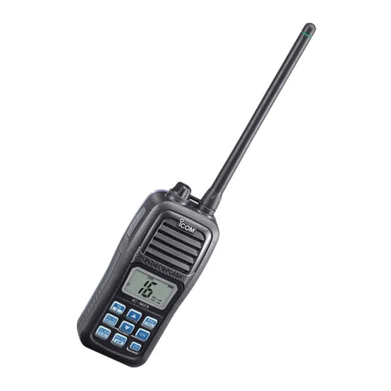
Page 10: Panel Description
PANEL DESCRIPTION ■ Front, top and side panels q ANTENNA CONNECTOR (p. 2) Connect the supplied antenna here. w DC JACK [DC] (p. 23) Connect the charger or optional cable here. q To remove the [DC] jack cap, rotate it counter clockwise. - Page 11 PANEL DESCRIPTION t VOLUME/SQUELCH/MONITOR KEY [VOL/SQL MONI] u UP/DOWN KEYS [Y] or [Z] ➥ Push to enter the volume adjustment mode or the ➥ Push to select an operating channel. (pp. 8, 9) ➥ While in the Set mode, push to select the setting or squelch adjustment mode.
-
Page 12: Function Display
PANEL DESCRIPTION ■ Function display t CHARGE ICON (p. 23) Appears while charging. y BATTERY ICONS ➥ Displays the remaining battery capacity. Indication Charging Battery status Full Middle Exhausted required blinks when the battery is over charged. ➥ Scrolls while charging. (p. 23) u SCAN ICON (p. -
Page 13: Panel Description
PANEL DESCRIPTION !1 SUB CHANNEL READOUT !6 ATIS ICON (p. 9) ➥ Displays Channel 16 during a priority scan, Dualwatch “ATIS” appears when the channel group, which ATIS func- or Tri-watch. (p. 16) tion is activated, is selected. ➥ Displays the Set mode item while in the Set mode. (p. 17) (Available with German and Holland versions only.) ➥... -
Page 14: Basic Operation
BASIC OPERATION ■ Channel selection D Call channel IMPORTANT: Prior to using the transceiver for the first time, the battery pack must be fully charged for optimum Each regular channel group has a separate leisure-use Call life and operation (p. 23). To avoid damage to the trans- channel. - Page 15 BASIC OPERATION D USA, International, Canadian and ATIS channels For German and Holland versions The transceiver is pre-programmed with USA* , Interna- tional, Canadian* and ATIS* channels. Choose the appro- priate channel groups for your operating area. Hold down q Push [CH] to select a regular channel. w Hold down [CH] for 1 second, one or more times, to se- lect the desired channel group.
-
Page 16: Adjusting The Volume Level
BASIC OPERATION ■ Adjusting the volume level ■ Adjusting the squelch level The volume level can be adjusted using [VOL/SQL] and [Y] The squelch level can be adjusted using [VOL/SQL] and [Y] or [Z]. or [Z]. In order to properly receive signals, as well as for the scan q Push [VOL/SQL] once to enter the volume adjustment to effectively function, the squelch must be adjusted to the mode, then push [Y] or [Z] to adjust the volume level. -
Page 17: Receiving And Transmitting
BASIC OPERATION ■ Receiving and transmitting IMPORTANT: To maximize the readability of your trans- CAUTION: Transmitting without an antenna can damage mitted signal, pause for a second after pushing [PTT], the transceiver. hold the microphone 5 to 10 cm from your mouth and speak into the microphone at a normal voice level. -
Page 18: Call Channel Programming
BASIC OPERATION ■ Call channel programming ■ Volume Loud function Call channel is used to access Channel 16 (default; may dif- The Volume Loud function temporarily maximizes the vol- fer depending on the version). However, you can program ume level. the Call channel with your most often-used channel in each This function has no effect when the volume level is 31. -
Page 19: Lock Function
BASIC OPERATION ■ Lock function ■ Automatic backlighting This function lights the function display and keys, and is con- This function electronically locks all keys (except for [PTT], [VOL/ venient for night-time operation. The automatic backlighting SQL], [MONI] (VOL/SQL), [ ] (Hi/Lo) and [Y] or [Z]*) to pre- can be activated in the Set mode. -
Page 20: Scan Operation (Except Holland Version)
SCAN OPERATION (Except Holland version) ■ Scan types Set the TAG channels (scanned channels) before scanning. Scanning is an effi cient way to quickly locate signals over a Clear the TAG for unwanted channels which inconveniently wide frequency range. The transceiver has a priority scan stop scanning, such as those for digital communications. -
Page 21: Setting Tag Channels
SCAN OPERATION ■ Setting TAG channels ■ Starting a scan For more efficient scanning, add the desired channels as Set the Priority Scan function, Scan Resume Timer and Auto TAG channels, or clear the TAG on unwanted channels. Scan function in advance, in the Set mode. (p. 18) Channels that are not tagged will be skipped while scan. -
Page 22: Dualwatch/Tri-Watch (Except Holland Version)
DUALWATCH/TRI-WATCH (Except Holland version) ■ Description ■ Operation q Select Dualwatch or Tri-watch in the Set mode. (p. 19) Dualwatch monitors Channel 16 while you are receiving w Select the desired channel. on another channel; Tri-watch monitors Channel 16 and the e Hold down [DUAL] (SCAN) for 1 second to start Dual- Call channel while receiving another channel. -
Page 23: Set Mode
SET MODE ■ Set mode programming D Set mode operation The Set mode is used to change the settings of transceiver's q Turn OFF the power. functions: Beep Tone function, Priority Scan function*, Scan w While holding down [VOL/SQL], turn ON the power to resume timer*, Auto Scan function*, Dual/Tri-watch function*, Monitor key action, Automatic backlighting, LCD contrast enter the Set mode. -
Page 24: Set Mode Items
SET MODE ■ Set mode items D Scan resume timer “St” (Not available with Holland version) D Beep Tone function The Scan resume timer can be set as a pause (OFF) or “bP” timer scan (ON). Turn the key touch beep sound ON or OFF. •... - Page 25 SET MODE D Dual/Tri-watch function D Automatic backlighting “dt” “bL” (Not available with Holland version) This function is convenient for night-time operation. The Set the watch type to Dualwatch or Tri-watch. (p. 16) backlight can be selected from ON and OFF. •...
-
Page 26: Set Mode
SET MODE D Power Save function “PS” The Power Save function reduces current drain by turning OFF the receiver circuit for preset intervals. • OFF : The Power Save function is turned OFF. • ON : The Power Save function is turned ON. The Power Save function will be activated when no signal is received, and no operation is performed for 5 seconds Push... -
Page 27: Battery Charging
fi re. R DANGER! Use the battery only with the transceiver for which it is R DANGER! Use and charge only specifi ed Icom battery pack with specifi ed. Never use a battery with any other equipment, or for any Icom radios or Icom chargers. -
Page 28: D Charging Caution
CAUTION: DO NOT charge the battery outside of the specifi ed tem- has been not used for a long period of time. The battery pack will perature range: ±0˚C to +45˚C. Icom recommends charging the bat- have slowly self-discharged, even though it has not been used. If the tery at +20˚C. -
Page 29: Supplied Battery Charger
BATTERY CHARGING ■ Supplied battery charger ■ Optional battery charger D Charging Do not place the charger on a surface with any vibration. Otherwise the batter y pack might come out of the Do not use a charger other than the specifi ed one. charger, or the charger itself might fall. - Page 30 BATTERY CHARGING D AD-123 installation (continued) D Charging w Install the AD-123 into the holder space of the BC-119N • For BC-119N or BC-121N with the supplied screws as shown. The optional BC-119N provides rapid charging of the Li-ion battery pack. (Charging time: Approximately 2.5 hours) The following items are additionally required: Screws supplied with •...
-
Page 31: Battery Charging
BATTERY CHARGING D Charging from a cigarette lighter socket • For BC-121N Use the optional CP-24 charge CIGARETTE LIGHTER CABLE from a cigarette lighter socket. The optional BC-121N allows up to six battery packs to be Charging time: Approximately 8.5 hours. charged simultaneously. -
Page 32: Troubleshooting
TROUBLESHOOTING PROBLEM POSSIBLE CAUSE SOLUTION REF. The transceiver does not turn • The battery is exhausted. • Recharge the battery pack. p. 23 • The battery pack is not correctly in- • Correctly insert the battery pack. p. 3 serted. No sound from speaker. -
Page 33: Vhf Marine Channel List
VHF MARINE CHANNEL LIST Channel number Frequency (MHz) Channel number Frequency (MHz) Channel number Frequency (MHz) Channel number Frequency (MHz) USA* CAN Transmit Receive USA* CAN Transmit Receive USA* CAN Transmit Receive USA* CAN Transmit Receive 156.050 160.650 157.050 161.650 156.375 156.375 157.325 161.925 156.050 156.050... -
Page 34: Specifications And Options
SPECIFICATIONS AND OPTIONS ■ Specifi cations D RECEIVER D GENERAL • Frequency coverage : Transmitting 156.000–161.450 MHz • Receive system : Double-conversion superheterodyne • Intermediate frequency : 1st 21.7 MHz, 2nd 450 kHz Receiving 156.000–163.425 MHz • Sensitivity (20 dB SINAD) : –4 dBµ... -
Page 35: Options
Approved Icom optional equipment is designed for optimal performance when used with an Icom transceiver. Icom is not responsible for the destruction or damage to an Icom transceiver in the event the Icom transceiver is used with equipment that is not manufactured or approved by Icom. - Page 36 < Intended Country of Use > A-6925H-1EX Printed in Japan 2011 Icom Inc. © 1-1-32 Kamiminami, Hirano-ku, Osaka 547-0003, Japan Printed on recycled paper with soy ink.
Need help?
Do you have a question about the IC-M23 and is the answer not in the manual?
Questions and answers