
Related Manuals for Mastech MS8268


Summary of Contents for Mastech MS8268
- Page 1 Mastech MS8268 HANDHELD DIGITAL MULTIMETER OPERATOR’S INSTRUCTION MANUAL http://www.HisTest.com...
-
Page 2: Table Of Contents
Table Table Table Table of of of of Contents Contents Contents Contents Table Table Table Table of of of of Contents Contents Contents Contents TITLE TITLE PAGE PAGE TITLE TITLE PAGE PAGE TITLE TITLE TITLE TITLE PAGE PAGE PAGE PAGE 1. -
Page 3: General General General Instructions Instructions
* When using this Multimeter, the user must observe all 1. 1. 1. 1. GENERAL GENERAL GENERAL GENERAL INSTRUCTIONS INSTRUCTIONS INSTRUCTIONS INSTRUCTIONS normal safety rules concerning: This instrument complies with IEC 1010-1 (61010-1@IEC: ― Protection against the dangers of electric current. 2001), CAT. -
Page 4: Symbols
* Do not apply any voltage measurement between the 10A * Replace the batteries as soon as the battery indicator ( terminal and the COM terminal. ) appears. With a low battery, the Meter might * Caution when working with voltages above 60Vdc or 30Vac produce false readings that can lead to electric shock and rms. -
Page 5: Safety Mechanisms
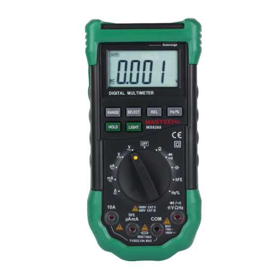
2. 2. 2. 2. DESCRIPTION DESCRIPTION DESCRIPTION DESCRIPTION * Any adjustment, maintenance or repair work carried out on 2.1 Instrument Instrument Instrument Instrument Familiarization Familiarization Familiarization Familiarization the meter while it is live should be carried out only by appropriately qualified personnel, after having taken into account the instructions in this present manual. -
Page 6: Lcd Display
Table Table Table Table 1. 1. 1. 1. Display Display Display Display Symbols Symbols Symbols Symbols ( ( ( ( continued continued continued continued) ) ) ) 2.2 LCD LCD Display Display Display Display Symbol Symbol Symbol Symbol Meaning Meaning Meaning Meaning See Table 1 indicated for information about the LCD display. -
Page 7: Keypad
2.3 Keypad Keypad Keypad Keypad Table Table Table Table 2. 2. 2. 2. Keypad Keypad Keypad Keypad( ( ( ( continued continued continued continued) ) ) ) See Table 2 indicated for information about the keypad Function Function Operation Operation performed performed Function... -
Page 8: Rotary Switch
2.5 Rotary Rotary Rotary Rotary switch switch switch switch 3. 3. 3. 3. FUNCTION FUNCTION FUNCTION FUNCTION DESCRIPTION DESCRIPTION DESCRIPTION DESCRIPTION A eleven-position rotary selector switch gives access to 3.1 General General General General Functions Functions Functions Functions the following quantities: 3 3 3 3 . -
Page 9: Data Hold Mode
NOTE: If you manually change the measurement range 3.1. 3.1.2 2 2 2 DATA DATA HOLD mode 3.1. 3.1. DATA DATA HOLD HOLD HOLD mode mode mode after entering the Data Hold modes, the Meter exits this Data Hold mode makes the meter stop updating the mode. -
Page 10: Resistance Measurement
ℕ For better accuracy when measuring the dc offset of an 3.2 Measurement Measurement Measurement Measurement Functions Functions Functions Functions 3.2.1 3.2.1 Voltage Voltage measurement measurement 3.2.1 3.2.1 AC AC and and DC DC Voltage Voltage measurement measurement ac voltage, measure the ac voltage first. Note the ac avoid avoid electrical... -
Page 11: Diode Test
ℕ The resistance function can produce enough voltage to 5. The meter will show the approx. forward voltage of the diode. forward-bias silicon diode or transistor junctions, causing In a circuit, a good diode should still produce a forward bias them to conduct. -
Page 12: Capacitance Measurement
To test the hFE of transistor: To measure capacitance: 1. Set the rotary switch to hFE hFE range. 1. Set the rotary switch to range. 2. Connect the “com” plug and “+” plug of the special 2. Connect the black and red test leads to the COM COM and multi-function socket to the COM COM and hFE... -
Page 13: Current Measurement
Note: Note: Note: Note: Distortion can cause multiple triggering of the frequency ℕ Reading is possible at input voltages above 3V rms, but the counter. Selecting a higher voltage range might solve this accuracy is not guaranteed. problem by decreasing the sensitivity of the meter. Also, try ℕ... -
Page 14: Technical Specifications Specifications
5. Break the circuit path to be tested. 10A: F 10A/250V ∅6.3×32 mm. ℕ Sample Rate: 3 times/sec for digital data. Touch the black probe to the more negative side of the ℕ Display: break; touch the red probe to the more positive side of the break. -
Page 15: Ac Voltage
4.2. 4.2. 4.2.5 5 5 5 Diode Diode Diode 4.2. Diode 4.2.2 4.2.2 4.2.2 4.2.2 AC AC Voltage Voltage Voltage Voltage Range Resolution Function Range Resolution Accuracy Display read approx. forward 400mV 0.1mV ±(3.0% of rdg + 3 digits) voltage of diode Forward DC Current: approx. -
Page 16: Dc Current
4.2. 4.2. 4.2. 4.2.9 9 9 9 DC DC CURRENT CURRENT CURRENT CURRENT - - - - By By Hz Hz range range range range: : : : Range Resolution Accuracy Overload protection: 250V dc or 250V ac rms. 400µA 0.1µA Input Voltage range: 0.6V-3V ac rms (Input voltage must be 4000µA... -
Page 17: Maintenance Maintenance
5. 5. 5. 5. MAINTENANCE MAINTENANCE MAINTENANCE MAINTENANCE 2. Disconnect test leads and/or any connectors from the terminals. This section provides basic maintenance information, 3. Use a screwdriver to unscrew the two screws secured on including fuse and battery replacement instructions. the battery cover. - Page 18 Figure Figure Figure 2 2 2 2 ..Battery Battery Battery Fuse Fuse Replacemen Replacemen Replacement t t t Figure Battery and and Fuse Fuse Replacemen CAUTION: CAUTION: CAUTION: CAUTION: “Using this appliance in an environment with a strong radiated radio-frequency electromagnetic field9approximately 3V/m), may influence its measuring accuracy.
Need help?
Do you have a question about the MS8268 and is the answer not in the manual?
Questions and answers