KRK ERGO User Manual
Enhaned room geometry optimization
Hide thumbs
Also See for ERGO:
- Quick start manual (2 pages) ,
- User manual (37 pages) ,
- User manual (44 pages)
Table of Contents
Advertisement
Advertisement
Table of Contents

Related Manuals for KRK ERGO

Summary of Contents for KRK ERGO
-
Page 2: Important Safety Instructions
NOTE: KRK Systems, LLC cannot be held responsible for damage, and, or including data loss caused by improper use of the unit and or the applications provided for use with the unit. - Page 3 IMPORTANT SAFETY INSTRUCTIONS CAUTION TO PREVENT ELECTRIC SHOCK, MATCH WIDE BLADE OF PLUG TO WIDE SLOT FULLY INSERT. ENGLISH:The apparatus shall be connected to a Mains socket outlet with a protective earthing connection. GERMAN:Das Gerät ist eine Wandsteckdose mit einem Erdungsleiter angeschlossen werden. FRENCH:L'appareil doit être connecté...
-
Page 4: Table Of Contents
Installation for Apple Mac OSX Systems ......................26 ERGO Calibration ............................29 Using ERGO Calibration Software (ERGO Cal) ....................30 ERGO Control Panel (Windows / Mac OSX) ....................40 Specifications ............................... 44 Frequently Asked Questions (FAQs) ......................45 Troubleshooting ............................ -
Page 5: Introduction
Thank you for purchasing your ERGO Room Correction and Audio Interface system. If you are already a KRK thanks for your continued use and support of our products. If you are new to KRK we are pleased that you chose ERGO as your room correction, we welcome you to our continually growing number of users. -
Page 6: Ergo And Roomperfect
The RoomPerfect algorithm in ERGO works on frequencies up to 500Hz, which equates to around 2ft, this works well in the studio environment where the user is working in a near-field mode and has a considerably smaller sweet spot than that of the home theatre. -
Page 7: Features
Professional calibrated measurement microphone and microphone stand adapter. As ERGO uses new some new technology you may not be familiar with, please refer to the glossary at the back of this manual to get more information about any of the terms used. -
Page 8: How Ergo Works
5. How ERGO works ERGO takes a stereo audio stream from the analog or digital (S/PDIF or FireWire input) domain and processes it though a 96 kHz room correction algorithm. All incoming analog audio is sampled at 96 kHz, while incoming digital audio is sample rate converted up to 96 kHz for processing. -
Page 9: Back Panel Connections
It is recommended that you only use the microphone supplied with ERGO for room calibration. ERGO supplies a 15V phantom power source to its microphone, and using other microphones for calibration may result in poor room analysis and improper correction filters. -
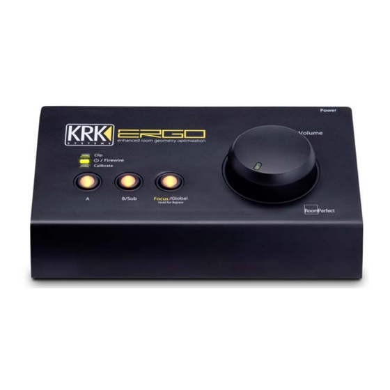
Page 10: Front Panel Features
Headphones Level Control (Located on Side Panel) – The headphones output level control is an illuminated dial on the left hand side of the unit. NOTE: The high quality headphone amp in ERGO is capable of providing a high output level to certain headphones, please start with a low level and rise slowly to maintain comfortable and non-damaging levels. -
Page 11: Placing Your Monitoring System
One of the great advantages of ERGO and the RoomPerfect technology is overcoming some traditional limitations. When it comes to placement of traditional monitors it is actually possible to think differently with ERGO because of its use of RoomPerfect™, i.e. to break away from conventional ‘free space’ placement. -
Page 12: Stereo Monitor Placement
There are two basic elements to consider before achieving the best possible performance from your monitors: a. Room Correction / Treatment - either acoustic, or digital (as ERGO) or a combination of these methods. b. Optimal Positioning – This covers the placement of all monitors, and subwoofers in the room. -
Page 13: Subwoofer Placement
11. Subwoofer Placement Note: A properly set up subwoofer system extends the bass response of the main stereo monitors down into the 30- Hz range, but without exaggerating bass response in the room. Improper setup may cause an exaggeration of bass response in the room, which in turn may cause the engineer to mix in less bass energy than desired. -
Page 14: Setting Monitor And Subwoofer Levels
Smartphone/iPhone applications. Set the low-pass filter on the subwoofer back plate to 80 Hz Send a one octave wide, band-pass pink noise signal to your monitoring system (the main speakers from ERGO, or from the subwoofer if using the internal crossover). A good choice is 500 to 1,000 Hz band-passed pink noise, which is within the fundamental frequency range of many vocalists, and minimizes high-frequency problems but doesn't excite the subwoofer. -
Page 15: Connecting Ergo To Your Monitoring System
Installing ERGO. 14. Connecting ERGO as an audio interface with a dual stereo monitoring system Below is the standard configuration when using ERGO as an audio interface with room correction for two pairs of stereo studio monitors:... - Page 16 15. Connecting ERGO as an audio interface with a 2.1 monitoring system Below is the standard configuration when using ERGO as an audio interface with room correction for a single set of stereo monitors augmented by a subwoofer. Here ERGO allows the user to adjust the crossover frequency from the control panel while you are in the sweet spot.
- Page 17 16. Connecting ERGO to an audio interface using dual 2.1 monitoring systems. Below is the standard configuration when using ERGO as an audio interface with room correction for two pairs of stereo studio monitors, both augmented by subwoofers. Here the subwoofer takes the signals from audio and performs crossover functionality before passing the high pass filtered output to the main monitors, Note: in this configuration the sub can only be bypassed using a footswitch where possible.
- Page 18 Subwoofer). Below a 2.1 system is shown, you can also apply the same principle using a dual stereo monitoring system. Note: ERGO uses a mono summed signal from the B Left output only, this should be the only connection you make to your subwoofers LEFT input.
- Page 19 18. Connecting ERGO to an existing audio interface This configuration is identical to using ERGO as stand-alone device. Here ERGO simply sits in the path between your existing audio interface and your monitors. In this mode ERGO will perform correction on the signal appearing at either the digital or analog inputs.
-
Page 20: Connecting Ergo To Your Computer
1GB RAM, 10 MB hard disk space, 800 x 600 monitor resolution (or higher) 4 or 6-pin FireWire port (6-pin port required to FireWire to supply power to ERGO) AC outlet (for ERGO power supply if power is not supplied via FireWire). -
Page 21: 94/Firewire Considerations
IEEE 1394 specification. Improper shielding and/or grounding are common causes of cable issues, always ensure you use the cable supplied with ERGO, or if connecting to a 4- pin or 9-pin port, we advise purchasing high quality cables from good quality, branded suppliers. -
Page 22: Preparing For Software/Driver Installation
So now you have positioned and connected your monitoring system and you are prepared with the right knowledge to connect to your computer via Firewire. The next step is to install ERGO’s drivers and software on to your computer. Page | 22... -
Page 23: Installation For Microsoft Windows Systems
22. Installation for Microsoft Windows Systems Note: Please ensure ERGO is not connected to your computer before starting this procedure 1. If you have downloaded the zipped file from the website please unzip the file by double clicking the icon with your left mouse button. - Page 24 7. After these messages, you will see the screen below; please quit any running applications and press “Next” to continue. 8. You will see the following screen. Again ensure ERGO is not connected to your system yet then press “Next” to begin installing the driver...
- Page 25 13. Once the process is completed you will see the screen below. At this point you can now connect ERGO to your computer and begin the calibration process described later in this document.
-
Page 26: Installation For Apple Mac Osx Systems
23. Installation for Apple Mac OSX Systems Note: Please ensure ERGO is not connected to your computer before starting this procedure: NOTE – Always check www.krksys.com for the latest ergo firmware, drivers and software. Running the latest installer will ensure that the correct drivers are used, thus preventing any unexpected behavior. - Page 27 5. You will see the following screen. Again ensure ERGO is not connected to your system yet then press “Install” to continue. 6. Next, you will need to enter your systems password to allow the installer to make changes. If you don’t have a password just leave the password field blank and press “OK”...
- Page 28 If using this manual you can disregard that document and close TextEdit 9. At this point you can now connect ERGO to your computer and begin the calibration process described in the next section:...
-
Page 29: Ergo Calibration
Room Knowledge, then applies to the selected monitors and stored within ERGO ERGO relies on a new way of measuring the room. Using traditional test signals such as pink noise normally means a trade-off between signal-to noise ratio (SNR) and frequency resolution. Long analysis windows lead to high frequency resolution but poor SNR due to the low number of averages. -
Page 30: Using Ergo Calibration Software (Ergo Cal)
If this is a new install and ERGO Cal has already been auto-started, please move to step B 1. Double-click the left button of your mouse m on the ERGO Cal icon (For Windows this will be a shortcut on the desktop, or in a folder called KRK ERGO within your “Programs”... - Page 31 3. ERGO Cal will now search for ERGO and begin communicating, once complete you will see this message: 4. Now ERGO Cal has detected you ERGO unit, please press the info button on the right hand of the current window.
- Page 32 Monitor and Subwoofer Levels”. 7. You will then be asked if you are using ERGO in subwoofer (2.1) mode, your answer will determine how ERGO’s A and B switches operate. If you select “No”, the A/B switches will alternate between the A and B monitors. If you select “Yes”...
- Page 33 9. If you chose to use ERGO in Subwoofer mode, the next window may tell you to press any of ERGO’s required buttons, please follow the guidance. When given the prompt below confirming both buttons are on press ENTER to continue 10.
- Page 34 13. You will then see the following message informing you to set the volume knob to the 12 o’clock (or North) position. This is a necessary step in order to set the position of the volume knob for the first calibration tones, so that they are at a safe low level.
- Page 35 LEFT monitor, as each side is measured independently. 18. If the volume needs adjusting ERGO Cal will ask you to adjust the level, please follow the messages until you see the screen below and press ENTER to continue. Note: If you cannot get enough level from your monitors, press “No”...
- Page 36 LEFT monitor, as each side is measured independently. 22. If the volume needs adjusting ERGO Cal will ask you to adjust the level, please follow the messages until you see the screen below and press ENTER to continue. Note: If you cannot get enough level from your monitors, press “No”...
- Page 37 Until you see this screen then STOP and read the next section before moving on. 25. Next, ERGO Cal will measure the other positions in the room. The number of room positions needed depends on the value of Room Knowledge. If it is below 90% after the third measurement, ERGO Cal automatically includes extra room measurements until a Room Knowledge of 90% or better has been achieved.
- Page 38 26. Place the microphone in your first position and press ENTER to continue. ERGO will then analyze that position and then ask you to re-position the microphone to the next position. Follow the process until you have at least 90% room knowledge.
- Page 39 ERGO 30. You may now quit ERGO Cal and begin using ERGO following the guide in the next section. If you have another set of monitors connected and ready to calibrate simply press enter and the procedure will re-start. If you wish to store your measurement data simply press the “SAVE”...
-
Page 40: Ergo Control Panel (Windows / Mac Osx)
26. ERGO Control Panel (Windows / Mac OSX) Once ERGO is installed and calibrated it will be ready for use with any audio application or operating system which is currently supported. The control panel to access specific settings can be found in you “Programs” folder and the icon looks like this:... - Page 41 Speaker Mode Allows you to select to use dual “STEREO A/B” or “2.1 A+B(SUB)” id using a system augmented with a subwoofer. Note: If in “STEREO A/B” mode no crossover fader or value will be shown If selecting 2.1 Mode, as shown below, a fader will appear along with a value for the crossover frequency. Use the fader to adjust your crossover settings, please see the section on setting levels, or your systems guidance for subwoofer crossover frequencies.
- Page 42 ERGO was started in Analog mode. Use the ERGO Control Panel to select the SPDIF Input. If the SPDIF Input is not working, ERGO is probably not locking its clock to a SPDIF clock. Check your cables and the audio output selection in your DAW application.
- Page 43 ERGO system. Windows users will see the supported driver categories such as Direct X, Wave and ASIO in the audio application and can control Windows use of ERGO in the “Sounds (and Audio Devices” page of the Windows control panel.
-
Page 44: Specifications
27. Specifications ® Processing 400MHz Analog Devices Blackfin RoomPerfect Algorithm Sample Rate 96KHz Room Correction Frequencies 20-500Hz Room correction Filter 1024 tap Finite Impulse Response S/PDIF Input Operating Range 44.1 kHz to 96 kHz S/PDIF conformity IEC60958-3 Dynamic Range 96 dB system (component 118dB) System THD+N <0.025% using 0 dBFS input and 22-22kHz Band Pass Filter Internal Sample Rates... -
Page 45: Frequently Asked Questions (Faqs)
What is ERGO? ERGO is an audio interface with built in digital room analysis and correction system. It consists of the ERGO unit, a measurement microphone and control software. These three pieces are used to measure and analyze phase and frequency problems within a listening environment and then a powerful digital signal processor in the ERGO hardware unit processes audio to correct for these problems. - Page 46 Can ERGO work with two sets of speakers? Yes, ERGO can switch between A and B speakers via its front-panel controls. Each set of speakers will need to be calibrated and will have their own correction filters so that when you are comparing or “A/B’ing” a mix, the specific correction for the selected monitors is engaged.
-
Page 47: Troubleshooting
Your computer does not have a 6 pin FireWire port on it. If you have a 9-pin port you will need to purchase a 9-pin to 6-pin cable in order to use with ERGO. Please ensure you buy a high quality cable from a well known brand as these are usually built to the 1394 specification and are more reliable than cheap alternatives. - Page 48 The Calibration Microphone appears not to be working You need to have the Calibrate switch on the back of ERGO pushed in order for the microphone to work. Make sure the Calibrate LED on the Front Panel is illuminated. Use only the KRK measurement microphone! Don't plug in any other microphone in for calibration.
-
Page 49: Glossary
30. Glossary A-D Convertor The conversion of analog data or information into digital or binary form (See binary). ASIO Audio Stream Input Output. ASIO, developed by Steinberg, is a cross-platform, multi-channel audio transfer protocol. It allows software to have access to the multi-channel capabilities of a wide range of powerful sound cards. Binary A digital numbering system based on two where data is expressed as combinations of "0"s and "1"s). - Page 50 A measure of how much processing is being performed in the room correction filters. The room correction score for a specific RoomPerfect™ filter can be viewed by pressing the Info button from the initial (ERGO is ready to measure your room) screen.
-
Page 51: Further Assistance
31. Further Assistance: We hope that this help document gives you all the information you need to get up and running. If you have any additional questions, please feel free contact our Customer Support Monday through Friday at +1 954.9499600 from 9AM to 6PM EST.
Need help?
Do you have a question about the ERGO and is the answer not in the manual?
Questions and answers