Infinity Bass Link Service Manual
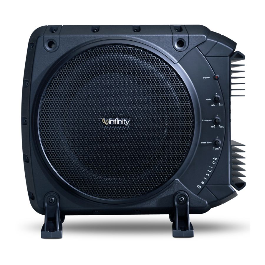
Powered automotive subwoofer
Hide thumbs
Also See for Bass Link:
- Service manual (55 pages) ,
- User manual (8 pages) ,
- Instructions manual (8 pages)

Related Manuals for Infinity Bass Link


Summary of Contents for Infinity Bass Link
- Page 1 Models: BassLink BassLink (Remote Level Control Ready) BassLink X Powered Automotive Subwoofer SERVICE MANUAL Infinity Systems, Inc. 250 Crossways Park Dr. Woodbury, New York 11797 Rev 2 7/2003...
-
Page 2: Table Of Contents
ALL MODELS BASSLINK SPECIFICATIONS …………………………………………..……………2 CONNECTIONS/APPLICATIONS ………………………………………3 TUNING BASSLINK…………………………………………………….…6 TROUBLESHOOTING ……………………………………………………7 TEST SETUP PROCEDURE ……………..………..……………………8 BASSLINK (Original version without Remote Level Control jack) SERVICE BULLETIN INF2000-03 ………………………………………10 EXPLODED VIEW …………………………………………….…..………11 MECHANICAL PARTS LIST ……………….………………………….…12 BLOCK DIAGRAM …………..……………..………….………………….13 PCB DRAWINGS …………………………….……………………………14 ELECTRICAL PARTS LIST ………………………………………………24 SCHEMATICS …………………………………………………………..…29 PACKAGING …………………………………………………………….…31... -
Page 3: Specifications
DC Offset Dimensions: Weight Infinity continually strives to update and improve existing products, as well as create new ones. The specifications and construction details in this and related Infinity publications are therefore subject to change without notice. Specifications 200W RMS @10% THD 120W RMS @1% THD 20Hz –... -
Page 4: Power Connections
To help you plan your installation, we included five system applications in Figures 6 through 10 on pages 3 through 5. For more system ideas, see your authorized Infinity car-audio dealer. Note: The applications show the optional remote SUB LEVEL control which installs under the dash- board for easy in-car bass level adjustments. - Page 5 RCA Stereo Cables – (not supplied) Source Unit – LR Speaker Figure 8. BassLink audio connections for a head unit equipped with two line-level (RCA) outputs and two speaker-level outputs. RF LF Line-Level Outputs (on Source Unit) VIOLET GREEN/BLACK VIOLET/BLACK...
- Page 6 PPLICATIONS CONTINUED Figure 9. BassLink audio connections for a head unit equipped with four speaker-level outputs. VIOLET GREEN/BLACK VIOLET/BLACK GREEN RR LR Sub Level Speaker Wires Control (spliced) (optional) GRAY WHITE/BLACK GRAY/BLACK WHITE RF LF Speaker Wires (spliced) LF Speaker –...
-
Page 7: Controls And Functions
5. Listen to your system, making a mental note If necessary, consult your authorized Infinity of the amount of upper bass being reproduced. car audio dealer for help in tuning your system. -
Page 8: Troubleshooting
(see Tuning BassLink on the previous page). 3. Head-unit output is distorted or blown. See your authorized Infinity car audio dealer. • PROBLEM: No output from BassLink when head-unit fader control set to front or rear (in a 4-channel connection). -
Page 9: Test Setup Procedure
Cables should be connected to an integrated amplifier fed by the signal generator. Turn on generator and adjust so that speaker level input at the amplifier is 275mV, 40 Hz. Turn GAIN control full clockwise. Bass response should be heard and felt. Green servo light should not be illuminated. - Page 10 Basslink (Original version without remote level control jack)
-
Page 11: Basslink (Original Version Without Remote Level Control Jack)
4) Add these two components: 1.0 Meg ohm 1/8W resistor, Infinity part# 299-1M .01uf, 100v mylar capacitor, Infinity part# 140-PF2A103F Solder these parts in parallel (See Figure 2); and attach to original location shown (See Figure 3), which is in a narrow cavity between main power supply caps and transformer T101. -
Page 12: Exploded View
BassLink Exploded View... -
Page 13: Mechanical Parts List
BassLink Mechanical Parts List NLA-REPAIR MAIN ASS'Y PCB 1010DS150-1 AMP-SMD ASS'Y NLA-REPAIR TONE CONTROL PCB ASS'Y... -
Page 14: Block Diagram
BassLink Block Diagram... -
Page 15: Pcb Drawings
BassLink Main PCB... - Page 16 BassLink Main PCB (Cont.)
- Page 17 BassLink Main PCB (Cont.)
- Page 18 BassLink Main PCB (Cont.)
- Page 19 BassLink Main PCB (Cont.)
- Page 20 BassLink Main PCB (Cont.)
- Page 21 BassLink Tone Control/Switching Controller PCB...
- Page 22 BassLink Tone Control/Switching Controller PCB (Cont.)
- Page 23 Power Amp PCB...
- Page 24 Power Amp PCB (Cont'd)
-
Page 25: Electrical Parts List
BassLink Part# Reference Designator Main PCB Resistors 11016472j26 R212,R217,R281,R282,R283,R284 R260,R288 11016103j26 R117,R118,R119,R122,R123,R124 R132,R133,R137,R138,R140,R166 R167,R168,R201,R204,R208,R213 R265,R266,R269,R270 11016470j26 R165 11016223j26 R121,R134,R164 11016393j26 R163,R157 11016100j26 R162 11016562j26 R159 11016102j26 R136,R158 11016222j26 R216,R243,R244,R245 11016182j26 R145 11016221j26 R156 11016270j26 R126,R127 11016104j26 R120,R135,R255 11112332j10 R143,R144 11016473j26 R148 11016513j26 R202,R203,R214,R215,R261,R262... - Page 26 BassLink Electrical Parts List (Cont.) Part# Reference Designator 1353476m16 C123,C124 1302b221k503 C202,C204,C219 132103ja03 C155,C156 Semiconductors 19006m45581 U201 19510204gd 192027c1815gr Q108,Q110,Q115,Q120,Q121,Q151 Q271,Q272,Q273 192021d669a Q117 192027c2235y Q150 192028a1015gr Q107,Q109,Q113,Q114,Q116,Q152 192022b649a Q118 19216355ne06 Q111,Q112 197131n4148 D102,D103,D104,D110,D113,D143 D159,D160,D275,D276,D277,D278 19730sf16 D107 197101n5402 D101 197301604gd D105,D106 19915001503 D108,D109 Connectors...
- Page 27 BassLink Electrical Parts List (Cont.) Part# Reference Designator 11016104j26 R114,R150 11016100j26 R109 11016123j26 R104 11016562j26 R100 11016183j26 R152 11016471j26 R153 Capacitors 1302f104z503 C106,C107,C109,C111,C112,C133 1303f272ka04 C110 1353226m16 C108 1353337m16 C134 Semiconductors 197131n4148 D114,D111 19915000623 D112 192028a965y Q103 192028a1015gr Q105,Q119 192027c1815gr Q104,Q106 19301494cn U101 Miscellaneous...
- Page 28 BassLink Electrical Parts List (Cont.) Part# Reference Designator Capacitors 129a224j633 C215 129a823j633 C216 129a334j633 C260,C261,C262,C263 1302b101k503 C214C217,C242,C252,C253 1302f104z503 C229,C231,C233,C234,C235 C268,C269,C274 132103j503 C270,C271 129a104j633 C211 129a394j633 C210 1353106m50 C228,C230,C232,C266,C267 1353476m16 C251 1353226m16 C264 Semiconductors 19006m45581 U200,U203,U204,U205,U206 19510204gd LD201 192027c1815gr Q200,Q201 192028n1015gr Q202 197131n4148 D201,D202...
- Page 29 BassLink Electrical Parts List (Cont.) Part# Reference Designator Semiconductors 19016t1072dts 19209124126qs Q1,Q4,Q5 19209139066qs Q2,Q8 19209210376qs Q7,Q9 19209215146rs Q3,Q6 19703rls4148s D1,D2,D3,D4,D5,D6 19915000563s Z1,Z2 19915001203s Z5,Z6 19915001503s Z3,Z4 192233IRF640 192232irf9640 Miscellaneous 12214121j4180 12214350j4180 1759f40hr2 Description I.C TL072CDT DualOp-Amp SMD TRANS, NPN 50V 0.15A 2SC2412K TRANS, NPN 120V 005A 2SC3906K TRANS, PNP 50V 0.15A 2SA1037K TRANS, PNP 120V 0.05A 2SA1514K...
-
Page 30: Schematics
BassLink Schematics... - Page 31 BassLink Schematics (Cont.)
-
Page 32: Packaging
BassLink Packaging... - Page 33 Basslink (Version with remote level control jack) Basslink X...
-
Page 34: Service Bulletin Inf2003-01
1) Set the unit on a padded surface and remove all external cables. 2) On the amplifier faceplate, remove 3) Pull amplifier assembly from the enclosure. Unplug ribbon cable at M202 and Molex speaker connector at M101; remove amplifer. 4) Check Main PCB for a damaged (open) trace in the main 12VDC path; see exact location shown in the two illustrations. -
Page 36: Mechanical Parts List
BASSLINK TOP ENCLOSURE 366.5*322*105.25H BLACK ABS BASSLINK X - TOP ENCLOSURE 366.5*322*105.25H BLACK ABS Basslink Woofer 10" 4 ohm Basslink X - Woofer 10" 4 ohm LOGO INFINITY Basslink PASSIVE RADIATOR Basslink X - PASSIVE RADIATOR MICA ISOLATOR TO-220 18 X 13mm... -
Page 37: Block Diagram
Block Diagram... -
Page 38: Pcb Drawings
Switching Controller/Tone Control PCB's... - Page 39 Switching Controller/Tone Control PCB's (Cont.)
- Page 40 Main PCB...
- Page 41 Main PCB (Cont.)
- Page 42 Main PCB (Cont.)
- Page 43 Power Amp PCB...
- Page 44 Power Amp PCB (Cont'd)
-
Page 45: Electrical Parts List
BASSLINK (w Level Control jack) BASSLINK X Part# Description Main PC Board Assembly Resistors 11016000j26 R170,171,172 11016101j26 R129,131 11016102j26 R136 11016103j26 R132,133,137,138,140,201,204,208,213, 265,266,269,270 11016104j26 R135,255 11016182j26 R145 11016201j26 R205,206,207,209,258,259,267,268 11016221j26 R156 11016222j26 R216,243,244,245 11016223j26 R134 11016243j26 R210,211 11016270j26 R126,127 11016471j26 R128,130 11016472j26 R212,217,260,281,282,283,284,288... - Page 46 Wafer 12PIN PITCH=2.0mm Wafer 2PIN PITCH=3.96mm 4PIN Universal Interface Connector RCA JACK 4PIN SPEAKER WIRE ASS'Y #1015 400mm RES, 10 ohms 1/6W ±5% CF 26mm RES, 1K 1/6W ±5% CF 26mm RES, 10K 1/6W ±5% CF 26mm RES, 100K 1/6W ±5% CF 26mm RES, 1M 1/6W ±5% CF 26mm...
- Page 47 Part# Description 11112332j10 R143,144 11130621jk3 R141,142 Capacitors 1302f104z503 C106,107,109,111,112,113,127,128,133, 144,160,305,306 1303f272ka03 C110 132103j503 C273 1353105m50 C303 1353106m50 C301,302 1353107m16 C129,130 1353226m16 C108 1353227m16 C161 1353337m16 C114 1353475m50 C304 1353476m16 C123,124 1353476m25 C272 1354337m25 C134 Semiconductors 19915000625 D112 19915001505 D108,109 192011d669a Q117 192012b649a Q118...
- Page 48 Part# Description 11016333j26 R253,277 11016392j26 R224 11016393j26 R223 11016432j26 R279 11016472j26 R275,276 11016473j26 R257,273,290 11016474j26 R220,278 11016511j26 R200,256,286 11016562j26 R238 11016683j26 R251 11016755j26 R293 115v503b101 VR201 115v503b201 VR202,203 Capacitors 129a104j633 C211 129a224j633 C215 129a334j633 C260,261,262,263 129a394j633 C210 129a823j633 C216 1302b101k503 C214 1302b101k503 C217,242,252,253...
- Page 49 Diode 15V 5% ZENER BZX84-C15 Ferrite core LS-A6206-ST EFD-30 Inductor 35uH Wafer 40PIN PITCH=2.54mm HR2*40 SCREW M3*8 SCREW M3*12 SCREW 3*8 FIBER WASHER 3*8*0.3t LED HOLDER 10.5H SCREW 4*14 SCREW 4*14 CAP, CA 0.1u 50V SPEAKER WIRE ASS'Y #1015 400mm...
- Page 50 Part# Description 162a600d001 162a600d002 193201815t2 Q10,1 600n8402000 T/C TO L/C-13 602p8300800 R/P TO PS-1 602p8301200 R/P TO T/L COVER-6 602p8301600 H/S TO DS-100 PCB-1 606c8301008 PCB TO BOSS-2 606p8201000 FUSE HOLDER-2 606p8301000 RCA JK-1/AC JK-2,PCB TO BOSS-2 606p8401200 R/P TP T/L COVER-8,L/C TO T/C-2 607p4300800 PCB TO H/S-2 607p8300800...
- Page 51 Main/Tone Control/Switching Controller...
- Page 52 Main/Tone Control/Switching Controller Part1...
- Page 53 Main/Tone Control/Switching Controller Part2...
-
Page 54: Schematics
Schematics (Cont.) -
Page 55: Packaging
Ref# Part# Description 704A150 PLASTIC BAG 706SB150 BASSLINK FOAM ENDS 703BH150-1 BASSLINK - BRACKET(H) 215.7*81*33*5T (BLACK) 703BH150W BASSLINK X - BRACKET(H) 215.7*81*33*5T (WHITE) 703BV150 BASSLINK - BRACKET(V) 255*64.5*33*5T (BLACK) 703BV150W BASSLINK X - BRACKET(V) 255*64.5*33*5T (WHITE) 704B150 PLASTIC BAG 650HB150 BASSLINK HEX BOLTS M5x0.8P x 180L 650HB150W BASSLINK X HEX BOLTS M5x0.8P x 180L... -
Page 56: Integrated Circuit Diagrams
Integrated Circuit Diagrams MOSFET, TO220 MOSFET IRF640, 9640 IRFZ44/STP55NE06 Q11, 10 Q111, 112 1. G 1. G 2. D 2. D 3. S 3. S IC TL494 PWM U101 OPAMP, DUAL 8 PIN 4558L U201, 200, 203, 204, 205, 206 TRANS, PNP, 2SA1015GR, 2SA965Y Q107, 109, 113, 114, 116, 152, 118 202, 103, 105, 119...
Need help?
Do you have a question about the Bass Link and is the answer not in the manual?
Questions and answers