GE PT920 Technical Service Manual
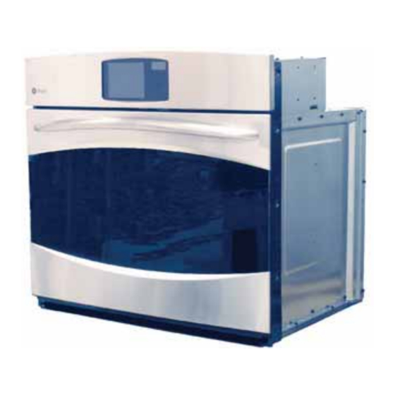
30-in. built-in wall ovens
Hide thumbs
Also See for PT920:
- Owner's manual (140 pages) ,
- Brochure (24 pages) ,
- Dimensions and installation information (3 pages)

Related Manuals for GE PT920


Summary of Contents for GE PT920
- Page 1 GE Consumer & Industrial Technical Service Guide August 2008 30-in. Built-In Wall Ovens PT920 PT960 31-9174 GE Appliances General Electric Company Louisville, Kentucky 40225...
- Page 2 If grounding wires, screws, straps, clips, nuts, or washers used to complete a path to ground are removed for service, they must be returned to their original position and properly fastened. GE Consumer & Industrial Technical Service Guide Copyright © 2008 All rights reserved.
-
Page 3: Table Of Contents
Table of Contents Bake Element ..................................31 Broil Element ..................................22 Component Locator Views ............................13 Control Board Testing ..............................40 Control Compartment Access.............................19 Control Features ................................6 Convection Bake Element .............................24 Convection Fan Blade and Motor ..........................23 Cooling Fan ..................................32 Diagnostics and Service Information ........................37 Door Assembly ...................................16 Door Hinge Receivers ..............................30 Electronic Oven Control ..............................34... -
Page 4: Introduction
Introduction These 30-in. wall ovens have superior style and performance. These ovens feature electronic controls that utilize the precision of modern digital technology. Additional features include: • Glass Touch LCD Controls - Combine a smooth, easy-to-clean glass design with large, easy-to-read graphics to facilitate easier usage •... -
Page 5: Nomenclature
Nomenclature Model Number P T 9 6 0 B M B B GE Cooking Product Product Color P = Profi le SS = Stainless Steel BB = Black WW = White Confi guration Model Year Designator T = 30-in. Wall Oven... -
Page 6: Control Features
Control Features (Throughout this manual, features and appearance may vary from your model.) ge.com Touch Screen Touch the graphics on the interactive display to ELECT use the oven features. ONVECTION IGHT ONVECTION ROIL PTIONS OAST AVORITE ITCHEN ECIPE IMER IGHT... - Page 7 How to Set the Oven for Broiling Close the door. Always broil with the door foods that cook quickly, such as thin closed. strips of meat or fish may require a short preheating period of 2 to 3 minutes to Touch BROIL.
- Page 8 The adjustment will be retained in memory To unlock the control, touch the after a power failure. CLEAR/OFF pad for 3 seconds, until the home screen appears. Option–Proof ge.com Proofing PTIONS ■ The proofing feature maintains a warm Proofing will not operate when oven is above environment useful for rising yeast-leavened 125°F.
- Page 9 Option–Two Temps Two Temps PTIONS Use to set a first temperature with a cooking time and also a second temperature with a second cooking time. EMPS Touch OPTIONS. PPER OWER Touch TWO TEMPS. For double oven models only, touch On double oven models only. UPPER OVEN or LOWER OVEN to select the desired oven.
-
Page 10: Help Feature
Dehydrate Dehydration (Drying) is a method of preserving fruits, Touch ENTER. vegetables, herbs and meats by removing moisture so Touch START. bacteria, yeast and mold cannot grow and spoil the food. The oven uses an automatic set temperature and NOTES: the convection fan to remove moisture from the foods ■... - Page 11 Options–Settings Adjust the Oven Thermostat―Do It Yourself! PTIONS Note: Other adjustments controlled by Note: This adjustment will only affect baking and roasting temperatures; it OPTIONS - SETTINGS include: ETTINGS does not affect broiling, convection or • To set the Clock self-cleaning temperatures.
-
Page 12: Bake Element
• The convection fan will cycle on and off to Sales Mode change direction while cooking to best distribute hot air in the oven. The convection fan shuts off The oven control can be operated in SALES MODE. when the oven door is opened. When the unit is connected to 120 VAC from L1–N, the control will function normally. -
Page 13: Broil Element
Component Locator Views Wall Oven (Single Oven shown) Control Panel Door Lock Meat Probe Outlet Broil Element Oven Temperature Sensor 2 Lights Convection Fan Hidden Bake Element Oven Door Gasket Oven Door Control Compartment Bottom Double Wall Oven (Middle Trim Assembly Shown Removed) Vent Tube Relay Board Door Lock... - Page 14 Control Compartment Top of Oven (Single Oven and Top Double Oven) Cooling Fan Power Supply Board Clean FAD Thermal Door Lock Relay Board Door Switch LCD Control Board Back of Single Oven (All Rear Covers Shown Removed) Cooling Fan Bake FAD Thermal Broil Element Convection Element Convection Fan...
-
Page 15: Oven Component Access Chart
Oven Component Access Chart WARNING: • The single and double wall ovens are heavy and require two people to remove them from the installation. Care should be taken when removing and installing. • Sharp edges may be exposed when servicing. Use caution to avoid injury. Wear Kevlar gloves or equivalent protection. -
Page 16: Door Assembly
Oven Components To replace the door: Door Assembly With the door at the same angle as the removal The oven door can be separated into 2 assemblies. position, seat the indentation of the hinge arm The outer assembly consists of the outer panel into the bottom edge of the hinge slot. - Page 17 To remove the outer door assembly: To replace the inner door assembly: Remove the door. Remove the outer door assembly. (See Door Assembly Place the inner door assembly, gasket side up, on a protective surface. 2. Remove the four T15 Torx screws (2 on each side) that attach each door hinge to the inner Remove the four 1/4-in.
- Page 18 Remove the six 1/4-in. hex-head screws that Arrows on the side of the inner glass assembly hold the heat barrier to the inner door. Remove indicate the direction in which the inner oven door the barrier. glass is installed. The arrows should be pointing toward the oven cavity.
-
Page 19: Control Compartment Access
Oven Removal Control Compartment Access The replacement of certain components require It may be necessary to remove the oven from the oven removal. (See installation to gain access to some components. Oven Component Access Chart (See Component Access Chart WARNING: The oven is heavy and requires two people to remove it from the installation. -
Page 20: Lower Oven Control Compartment Access
Remove the two 1/4-in. hex-head screws from Lower Oven Control Compartment Access the relay board tray. Note: It may be necessary to remove the oven from the installation to gain access to some components. (See Component Access Chart To access the lower oven control compartment: Remove the upper oven door. -
Page 21: Rear Access Panels
Side Access Panels Rear Access Panels It is necessary to remove the side trims prior to The rear top access panel must fi rst be removed removing the side access panels. The oven must be before removing the upper rear access panel. (See removed to access the 1/4-in. -
Page 22: Oven Temperature Sensor
Oven Temperature Sensor Broil Element The oven temperature sensor can be tested from Note: The resistance of this component can be the EOC. (See .) The resistance Control Board Testing tested from the EOC. (See Control Board Testing of the temperature is: The broil element will not work if the meat probe is Ω... -
Page 23: Convection Fan Blade And Motor
Vent Tube/Smoke Eliminator Convection Fan Blade and Motor The oven vent tube/smoke eliminator is located in The Convection Fan Blade the top, left, front corner of the oven cavity above The convection fan blade is located on the back wall the broiler element shield. -
Page 24: Convection Bake Element
The convection fan will turn on (after a short delay). Convection Bake Element The fan may cycle on and off, and change direction in any of these modes, to best distribute hot air in Note: The resistance of this component can be the oven. -
Page 25: Logic Board
Logic Board Relay and Power Boards The relay board and the power board in the single To remove the logic board on single or double and upper ovens are located in the right side of the ovens: control compartment and are accessed through the Gain access to the control compartment. - Page 26 Lift the left rear corner of the tray over the wire Lower Oven (Double Wall Oven) tie and pull the tray forward and clockwise. The relay board for the lower oven in a double wall oven is located in the area between the two ovens. To remove the relay board (lower double wall oven): Access the lower oven control compartment.
- Page 27 The cam on the motor performs two functions: Lock Assembly Positions the lock hook in the door to prevent The motorized door lock assembly is located above opening during clean operation. the oven. The assembly consists of a lock motor cam and switch assembly, lock hook, mounting Operates the lock switches, which signal the plate, door switch, spring, and plunger.
- Page 28 Door Lock - Unlocked Position Mark and disconnect connectors from the lock assembly. Remove 2 hex-head screws and the lock assembly from the oven. Lock Assembly Caution: It is possible to reconnect the switch wiring incorrectly to the lock assembly. When reconnecting the wiring, make sure it is properly connected to the Strip Circuit lock assembly before turning the power back on.
-
Page 29: Thermal Switches
Note: The following is an indication of an open Thermal Switches clean FAD: A cooking mode is selected. When START is pushed, the control displays “F9 – FAD ERROR Limit Thermal Switch DETECTED – MODE CANCELED” then returns to The high limit thermal switch is wired in series with home. -
Page 30: Door Hinge Receivers
To remove the bake FAD thermal switch on single Door Hinge Receivers and upper double ovens: To remove the door hinge receivers: The bake FAD thermal switch is located on the back top side of the wall oven. (See Component Locator Remove the oven from the installation. -
Page 31: Meat Probe And Outlet
Bake Element Meat Probe and Outlet Note: The resistance of this component can be If equipped, the meat probe outlet is located on tested from the EOC. (See the top of the oven cavity, near the front. The meat Control Board Testing probe outlet is connected to the electronic oven The element is rated at 2100 watts, has an control. -
Page 32: Cooling Fan
Carefully move the insulation to access and Cooling Fan remove the two 1/4-in hex-head screws (one on each side of terminals) that hold the bake A cooling fan is controlled by the logic board and element to the oven. is located above each oven. On upper and single ovens, the cooling fan is in the rear wall on the left side of the control compartment. -
Page 33: Oven Light Assembly
4. Remove the six 1/4-in. hex-head screws that Oven Light Assembly hold the cooling fan to the oven and remove the cooling fan The ovens have two light assemblies in each oven cavity. The incandescent light assemblies are located on the top of the oven. The oven door switch monitors the position of the oven door and provides this information to the EOC. -
Page 34: Electronic Oven Control
Electronic Oven Control Overview The Electronic Oven Control (EOC) system consists of the glass touch board, logic board, power board, relay board(s), oven sensor, and door lock assembly. Caution: Components are electrically HOT on control when voltage is connected to range. Note •... - Page 35 Relay Board Note: There is one relay board for each oven. K10 K14 Convection Fan, Cooling Fan, Oven Light, Lock Motor Lock Motor Cooling Fan Clean FAD Thermal Convection Fan 12V, Linbus, Gnd (DC), -14V, Door Lock Enable Cooling Fan Bake Element Light Broil Element...
- Page 36 Glass Touch Boards (Shown with Logic Board) Glass Touch Board 1 Glass Touch Board 2 Logic Board Ferrite Wire Harness to J3 on Glass Touch Board 2 Wire Harness to J8 on Logic Board Note: The glass touch boards and the control panel front are one unit and are ordered as an assembly. Logic Board Lower Oven: Door Lock Motor Switch, 12 V and GND DC from Power Supply Board;...
-
Page 37: Diagnostics And Service Information
Diagnostics and Service Information Factory Test Mode The factory test mode can only be accessed during the fi rst 5 minutes after the unit is powered up. To access the factory test mode, press the following keys in sequence (press and release each key one at a time) within the fi... -
Page 38: Lock Assembly
If abnormal reading is observed, wiggle leads at disconnect block. If any variation occurs, replace. Resistance Measurement Chart Models Circuit Connector Terminals Ohms 1091 Ω @ Rm. Temp. PT920 9 to 10 1654 Ω @ 350°F Oven Sensor 2634 Ω @ 865°F PT960 Upper Oven 0 Ω... -
Page 39: Erc Failure Codes
ERC Failure Codes Failure Codes are accessed by pressing and holding the HOME and OPTIONS keys simultaneously for 3 seconds. Last 7 Failure F- Codes : The LCD screen will show the last 7 failure codes logged Upper 7 Fcode Log Lower 7 Fcode Log by the system. -
Page 40: Control Board Testing
Control Board Testing The resistance of various components can be checked from the Electronic Oven Control by the service technician to quickly identify failed or improper operation of certain oven components. For better clarity, some boards are shown with the top cover removed. Note: Colored dots on the relays match the color of the wire. - Page 41 Line Voltage Testing To test the line voltage at the relay board, the black wire is L1, The white wire is neutral, and the red wire is L2. The voltage should be approximately 120 VAC between L1 and N and approximately 240 VAC between L1 and L2.
-
Page 42: Schematics And Wiring Diagrams
Schematics and Wiring Diagrams WARNING: Disconnect electrical power before servicing. Caution: Label all wires prior to disconnection. Wiring errors can cause improper and dangerous operation. Verify operation after servicing. PT920 and PT960 Wiring Diagram (Continued Next Page) – 42 –... - Page 43 Schematic, Logic Board (Continued Next Page) – 43 –...
- Page 44 Schematic, Relay Board (Continued Next Page) – 44 –...
- Page 45 Wiring Diagram, Upper or Single Oven (Continued Next Page) – 45 –...
- Page 46 Wiring Diagram, Lower Oven – 46 –...
-
Page 47: Warranty
This warranty is extended to the original purchaser and any succeeding owner for products purchased for home use within the USA. If the product is located in an area where service by a GE Authorized Servicer is not available, you may be responsible for a trip charge or you may be required to bring the product to an Authorized GE Service location for service.