GE GEH50DEED Technical Service Manual
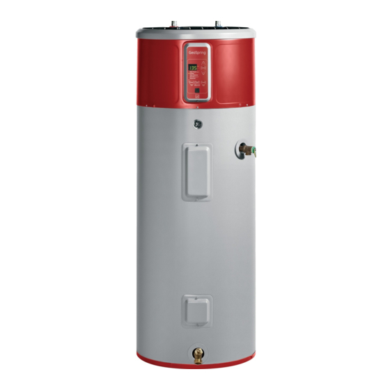
Hybrid water heater
Hide thumbs
Also See for GEH50DEED:
- Owner's manual (72 pages) ,
- Owner's manual & installation instructions (25 pages) ,
- Owner's manual (23 pages)

Related Manuals for GE GEH50DEED


Summary of Contents for GE GEH50DEED
- Page 1 GE Appliances Technical Service Guide ApriL 2012 GE Hybrid Water Heater GEH50DEED 31-9225 GE Appliances General Electric Company Louisville, Kentucky 40225...
- Page 2 GE Appliances Technical Service Guide Copyright © 2012 All rights reserved. This service guide may not be reproduced in whole or in part in any form without written permission from the General Electric Company.
- Page 3 Table courtesy of Shriners Burn Institute (Continued next page) – 3 –...
- Page 4 – 4 –...
-
Page 5: Table Of Contents
Table of Contents Anode rod ......................................53 Circuit Board Connections ................................38 Component Locator Views ................................28 Condensate Drain pan .................................. 57 Control Features ....................................23 Control panel...................................... 42 Dip Tube ....................................... 54 Drain Valve ......................................44 Electronic Expansion Valve (EEV) .............................. 60 Element Covers .................................... -
Page 6: Nomenclature
Nomenclature Model Number 50 D E E D SR A Brand Revision G = GE Color Fuel Type Sr = Gray Shark Skin E = Electric Body/Laser red Shroud High Efficiency Marketing Year H = Hybrid Medium D = 2012... -
Page 7: Introduction
Introduction The new GE Hybrid Water Heater has the following features: • Electric 50-gallon capacity • 240/208 VAC 30-amp circuit • Two 4500-watt heating elements • 600W compressor • 134a sealed system (27.34 oz.) • Temperature set range 100°F to 140°F •... -
Page 8: Technical Data
Technical Data FAN SHROUD EVAPORATOR COIL BLUE BLACK START BLACK CAPACITOR YELLOW MAIN BOARD BROWN CONDENSER COIL (non-replaceable) – 8 –... -
Page 9: Overview
Overview The cost of operating a traditional water heater has been reduced because this water heater uses heat pump technology. The heat pump removes heat from the surrounding air, heats the water, and moves the cooler air back into the room. WARM AIR What to expect it is normal for cool air to blow out the vents on the... - Page 10 Modes of Operation Heat Pump Mode – most energy-efficient mode, uses only the sealed system. The time required to heat water is longer, but should be adequate for normal demand households. it will take 3 to 4 hours to initially heat a tank to 120°F at room temperature (4 to 6 hours in a colder room).
- Page 11 Initial Start-up Upon power-up: 1. Default settings are hybrid mode and a water temperature setting of 120°F. 2. 0 to 2 minutes: Unit is silent. This 2-minute off-time prevents compressor damage. 3. 2 to 10 minutes: Compressor and fan turn on. This period is used to ensure the tank is full of water - dry tank test.
- Page 12 Dry Tank Test Upon initial installation, or anytime the power is off and power is then connected, the water heater will run a dry tank test before starting the selected heating mode. After approximately 2 minutes, the control will turn on the compressor and fan motor. The control will run the sealed system for 5 minutes and monitor the tank temperature from the T2 sensor.
-
Page 13: Temperature Chart
Temperature Chart The speed at which the temperature drops determines when and what heat source the control uses to recover. Heat Pump Mode Control checks T2 (tank sensor) less than set temperature T2 is less than set Has there temperature minus 5F been a flow (T2<... -
Page 14: Hybrid Mode
Hybrid Mode Control checks T2 (tank sensor) T2 is less than set temperature minus 30F (T2< ST-30F) less than set temperature T2 is less than set Has there temperature minus 5F been a flow Upper Element on until (T2< ST-5F) event? T2 reaches set Large flow of... - Page 15 High Demand Mode Control checks T2 (tank sensor) T2 is less than set temperature minus 20F (T2< ST-20F) less than set temperature T2 is less than set Has there temperature minus 5F been a flow Upper Element on until (T2< ST-5F) event? T2 reaches set Medium flow of...
- Page 16 Electric Mode Control checks T2 (tank sensor) T2 is less than set temperature minus 25F (T2< ST-25F) less than set temperature Has there T2 is less than set been a flow temperature minus 5F Upper Element on until event? (T2< ST-5F) T2 reaches set temperature minus 7F (T2 = ST-7F)
- Page 17 Vacation Mode Use this mode when hot water is not needed for an extended period of time. Default for vacation days is set at 7 days. Vacation days can be changed from 1 to 14 days. In this mode, the control will drop the water temperature down to 50ºF and will use the most-efficient heating mode to conserve energy while the heater is sitting idle.
-
Page 18: Installation
Installation Route to open drain line should be at least 3/4” (1.9cm) ID and pitched for proper drainage. A―Diameter of water heater plus 2” (5.1 cm) min. B―Maximum 2” (5.1cm) A 7" clearance is recommended with a minimum of 5-1/2" air space between any object and the front and back of the water heater and 7"... - Page 19 Electrical junction box (use PVC CEMENT only copper conductors) To electrical distribution panel Union To cold water supply Union Shut-off valve Hot water outlet to xtures Thermal expansion tank (if required) Jacket access panel Temperature and pressure-relief valve (shown in different location for clarity) Jacket access panel Auxiliary catch...
- Page 20 (Continued Next page) – 20 –...
- Page 21 240V Junction box cover Typical vertical Typical horizontal piping piping arrangement arrangement Factory Ground Water heater junction box House Ground (Continued Next page) – 21 –...
- Page 22 This guide recommends minimum branch circuit sizing based on the National Electric Code. refer to wiring diagrams in this manual for field wiring connections. BRANCH CIRCUIT SIZING GUIDE Compressor and fan turn off, upper heating element turns on for about 20 minutes –...
-
Page 23: Control Features
Control Features NTER DAYS (ONLY) YBRID EMAND LECTRIC (FAN OFF) ACATION POWER ILTER SAVER Hold for Hold to Hold to Override °F/°C PS-Power Saver Reset (Continued Next page) – 23 –... - Page 24 NTER DAYS (ONLY) YBRID EMAND LECTRIC (FAN OFF) ACATION POWER ILTER SAVER Hold for Hold to Hold to Override °F/°C PS-Power Saver Reset NTER DAYS NTER DAYS (ONLY) YBRID EMAND (ONLY) LECTRIC YBRID (FAN OFF) ACATION EMAND LECTRIC (FAN OFF) POWER ILTER ACATION...
- Page 25 mode the heating elements are activated sooner than in the Hybrid mode. (Continued Next Page) – 25 –...
- Page 26 Use a at screwdriver to turn valve. NOTE: Refer to the Hydrogen Gas Caution on page 4. (Continued Next page) – 26 –...
- Page 27 Tabs Filter Slots Over ow Main drain tube Direct the main drain tube into a drain – 27 –...
-
Page 28: Component Locator Views
Component Locator Views Front Control Housing Upper Element Cover and Styrofoam Insulation Removed Relief Valve T2 Tank Sensor Thermal Cutout Upper Element Cover Upper Element Lower Element Cover Removed Lower Element Cover Lower Element Drain Valve (Continued Next page) – 28 –... - Page 29 Machine Compartment – Front (Front Shroud and Front Shroud Cover Removed) T5 Ambient Thermistor Start Capacitor Display Control Panel ACM Module Connector* * Appliance Communication Module (ACM) Connector – for use with the ACM (sold separately). (Continued Next page) – 29 –...
- Page 30 Machine Compartment – Rear (Front and Back Shrouds and Front Shroud Cover Removed) Evaporator Fan Motor Evaporator Drain Pan (Continued Next page) – 30 –...
- Page 31 Machine Compartment – Right Side (Front and Back Shrouds and Front Shroud Cover Removed) T3b Evaporator Outlet Sensor Evaporator Electronic Expansion Valve (EEV) Compressor Accumulator Filter Drier T3a Evaporator Inlet Sensor Overflow Tube Primary Drain (Continued Next page) – 31 –...
- Page 32 Component Locator Views Machine Compartment – Left Side (Front and Back Shrouds and Front Shroud Cover Removed) Fan Shroud T4 Compressor Outlet Sensor Anode Access Cover – 32 –...
-
Page 33: Refrigeration System
Refrigeration System Electronic Expansion Valve (EEV) FAN SHROUD This valve replaces the capillary tube typically used in refrigeration appliances. The EEV meters the flow of liquid refrigerant entering the evaporator at a rate EVAPORATOR COIL that matches the amount of refrigerant being boiled off in the evaporator (gas). -
Page 34: Sealed System Service Overview
Sealed System Service Overview Evacuation and Charging Procedure WARNING: • Be careful when using a torch near plastic, mastic, and foam insulation. Use approved safety equipment and protect these items Access Valve from damage with the heat shield kit (part #WX5X8926), which includes the heat shield and thermal paste. - Page 35 Aluminum to Copper Tubing Repair Using 4. position the tubing and apply LOKprEp (part #Wr88X16). LOKRING Method Note: To prevent creation of leak paths through lengthwise groves, always clean tubing in a rotory direction. 1. Clean tubing on both sides of the fitting. 5.
-
Page 36: Aluminum To Copper Tubing Repair
6. Crimp the upper section of the connector, Aluminum to Copper Tubing Repair Using being careful not to bend or kink the aluminum SwageLok Method condenser tubing. Note: • LOKprEp not needed when using SwageLok method. • SwageLok part #WS86X10004 •... - Page 37 3. Cut the copper tubing close to the fitting. Note: The following step will require the use of a 9/16-in. wrench to hold the fitting body while tightening each of the two 5/8-in. hex nuts. 5. Tighten using 2 wrenches, 1 to hold the fitting body and 1 to tighten each hex nut.
-
Page 38: Circuit Board Connections
Circuit Board Connections Control Board K201 K203 K204 K202 J201 J603 J601 J604 J602 K201 – DLB (Double Line Break) J201 – Comp_No (Fan Motor) J601 – T2 (Tank Sensor) K203 – UE (Upper Element) J602 – T4 (Compressor Outlet Sensor) K204 –... -
Page 39: Machine Compartment Covers
Water Heater Components NOTICE: removal and/or replacement of the 3. Lift the front of the trim ring, push it back, then following components of the water heater requires a suspend it from the water heater. certified plumber: • Anode rod •... - Page 40 To remove the front shroud: To remove the rear shroud cover: Note: The front shroud is attached to the top of the 1. remove the front shroud cover. (See To remove tank with 5 screws and to the rear shroud with 4 the front shroud cover, this section.) tabs (2 on each side) that engage 4 slots located 2.
-
Page 41: To Remove Rear Shroud
7. push the junction box below the opening. To remove the rear shroud: Note: The rear shroud is attached to the top of the tank with 4 screws and 3 tabs, and to the rear shroud cover with 4 screws. 1. -
Page 42: To Remove Control Panel
Note: The rear shroud cover and the rear shroud Control Panel can be removed as 1 assembly. The control panel is attached to the front shroud To remove the rear shroud cover and the rear with a screw at the bottom and 2 tabs at the top shroud as 1 assembly: that grip the inside of the shroud. - Page 43 4. Tilt the top of the panel toward the right, then Cover Removed pull the top of the panel out of the notched opening in the front shroud. Notched Opening 7. Mark and disconnect wiring and disconnect the 4 wire harnesses from the control board. IMPORTANT NOTE: •...
-
Page 44: Drain Valve
Drain Valve Element Covers repair or replacement of the drain valve should be The upper element cover must be removed to performed by a licensed plumber. access the T2 tank sensor, thermal cutout (TCO), and the upper element. (See Component Locator Views The drain valve, located at the front bottom of the tank, has a standard garden hose fitting. - Page 45 Tank Sensor Evaporator Inlet Sensor The tank sensor (T2) is located above the thermal The evaporator inlet sensor (T3a), provides the cutout (TCO) and provides the control with a control with evaporator inlet temperature during resistance value for determining tank temperature. sealed system operation.
- Page 46 The sensor is inserted into a clip that is attached Evaporator Outlet Sensor to the evaporator inlet tube. The sensor location The evaporator outlet sensor (T3b) provides the is insulated with mastic. (See Component Locator control with evaporator outlet temperature during Views sealed system operation.
- Page 47 Note: Compressor Outlet Sensor • The position of the T3b sensor on the copper The compressor outlet sensor (T4) provides the tubing is critical. Ensure the sensor is attached control with compressor discharge temperature on the top side of the tube, between the 10 during sealed system operation.
-
Page 48: Thermal Cutout (Tco)
Ambient Sensor Thermal Cutout (TCO) The ambient sensor (T5) provides the control with a The TCO provides additional safety from the tank reading of room temperature as the evaporator fan overheating. draws air through the machine housing. The TCO is located between the T2 tank sensor and The control checks the sensor to confirm: the upper element. - Page 49 2. Carefully pull the upper element Styrofoam 4. Mark, then disconnect the wires from the TCO. insert straight out. 5. Lift each of the 2 clips that hold the TCO to the tank and pull the TCO up. Styrofoam Insert Clip Clip 3.
-
Page 50: To Replace Water Heater Electric Element
7. Using a 1½-in. socket, remove the element from Elements the water heater. replacement of the heating elements should be performed by a licensed plumber. The upper and lower heating elements are identical. Each heating element is rated at 4500 watts at 240 VAC. - Page 51 Upper Element Circuit (ambient) BLACK YELLOW WHITE WHITE BLUE ORANGE YELLOW K203 K201 BLACK GRAY CT101 VIOLET 170°F UPPER ELEMENT 4500W 12.8 ~ 18.75 A (Continued Next page) – 51 –...
- Page 52 Lower Element Circuit (ambient) BLACK YELLOW WHITE WHITE BLUE K204 ORANGE K203 K201 YELLOW BLACK GRAY CT101 YELLOW VIOLET 170°F LOWER ELEMENT 4500W 12.8 ~ 18.75 A – 52 –...
-
Page 53: Anode Rod
To replace the anode rod: Anode Rod 1. Disconnect power to the heater. replacement of the anode rod should be performed by a licensed plumber. 2. Shut off the water supply to the heater. The anode rod is magnesium wrapped around a 3. -
Page 54: Dip Tube
T2 sensor, be sure to align the hole so that it will spray water towards the T2 sensor. Orifice • When replacing the dip tube, use GE part #WS35X10072. 110-120°F Dip Tube Hole Relay Cover 60-120°F 60°F... - Page 55 5. press the screwdriver down until the cover is 9. Carefully peel back the foam seal from the top released from the top of the compressor flange. of the evaporator. Foam Seal 6. press the cover down and release it from the 2 10.
- Page 56 Note: In the following step, if it is difficult to stand 13. Cut off the plastic wire tie and remove the two behind the water heater, the fan assembly can be 1/4-in. hex-head screws that attach the fan lifted from the top and rotated to the left side. motor to the fan shroud.
-
Page 57: To Remove Condensate Drain Pan
4. remove the 1/4-in. hex-head screw that Condensate Drain Pan attaches the right side of the evaporator to the condensate drain pan. The condensate drain pan is located directly underneath the evaporator. The pan has a 5. remove the two 5/16-in. hex-head screws that primary drain outlet that is intended to transfer all attach the right side of the condensate drain condensate outside the machine compartment. -
Page 58: Single-Speed Compressor
it is necessary to remove the control panel to access Single-Speed Compressor the compressor external overload. (See Control Panel The compressor is a reciprocating type. refer to the mini-manual for the BTU/hour rating and the compressor capacity test specification. External The compressor utilizes a start capacitor rated Overload at 145 to 177 ufd. - Page 59 Heat Pump Circuit (ambient) BLACK GRAY YELLOW BLUE WHITE WHITE BLUE COMP ORANGE K202 K204 YELLOW K203 K201 BLACK GRAY CT101 LIGHT BLUE YELLOW EXTERNAL COMPRESSOR OVERLOAD VIOLET BLUE COMPRESSOR 170°F YELLOW BLACK BLUE START BLACK CAPACITOR YELLOW MAIN BOARD BROWN –...
-
Page 60: Electronic Expansion Valve (Eev)
Electronic Expansion Valve (EEV) The EEV is installed between the dryer outlet and the evaporator inlet. (See Component Locator Views The EEV meters the flow of liquid refrigerant entering the evaporator at a rate that matches the amount of refrigerant being boiled off in the evaporator (gas). The valve is designed to maintain proper superheat. (See Refrigeration System The EEV is a stepper motor expansion valve. - Page 61 To replace the electronic expansion valve (EEV): 6. If you are using a torch to replace the EEV valve, unsolder the EEV from the drier inlet tube 1. Turn power off. and the evaporator inlet tube using currently accepted procedures. 2.
-
Page 62: Service Diagnostic Mode
Service Diagnostic Mode To exit the service mode at any time, press and hold To enter the service diagnostic mode, press the UP and DOWN arrow buttons simultaneously and hold the UP arrow pad and the ENTER pad for 5 seconds and listen for the tones. simultaneously for 5 seconds. - Page 63 Three functions can be accessed while in the service Once the service mode is entered, all heating loads diagnostic mode: shut off and the first function VIEW SENSOR is initiated with t2 in the display. 1. View Sensors—Allows viewing the T2, T3a, T3b, T4 and T5 sensor temperatures.
- Page 64 To view the true sensor temperatures: To check and energize the heating components, while in the service diagnostic mode, press the 1. press the MODE button to HYBRID setting MODE button until the green light is next to HYBRID. (heating component status) and select a heating load.
- Page 65 Lower Element OFF Upper Element OFF To energize the upper element press ENTER. To energize the lower element press ENTER. upper element ON, 5 minute timeout. lower element ON, 5 minute timeout. pressing the DOWN arrow button will switch to pressing the DOWN arrow button will switch to compressor.
- Page 66 Compressor OFF After turning on a load, press the MODE button until the HEAT PUMP led light is lit. This will return the diagnostic screen to view sensor function where the sensor and it’s temperature can be observed. To energize the compressor press ENTER. Compressor ON, 10 minute timeout.
- Page 67 T2 sensor being viewed T3a sensor being viewed repeatedly alternates, sensor then temperature. repeatedly alternates, sensor then temperature. T2 sensor temperature being viewed T3a sensor temperature being viewed pressing the DOWN arrow button will switch to the pressing the DOWN arrow button will switch to the next sensor, T3a.
- Page 68 T3b sensor being viewed T4 sensor being viewed repeatedly alternates, sensor then temperature. repeatedly alternates, sensor then temperature. T4 sensor temperature being viewed T3b sensor temperature being viewed pressing the DOWN arrow button will switch to the pressing the DOWN arrow button will switch to the next sensor, T5.
- Page 69 Fault Count Status T5 sensor being viewed – The control counts the number of times a fault is recorded. A fault is not displayed to the consumer until 10 counts have been recorded to ensure a true failure has occurred (except 5 fault counts for dirty filter).
- Page 70 Fault counts for F5, F6, F7, F8: To view faults and counters, while in the service diagnostic mode, press the MODE button until the if fault code F5, F6, F7, or F8 is displayed, the faults green light is next to HIGH DEMAND. refer to failure of one of the sensors: T3a (F5), T3b (F6), T4 (F7) or T5 (F8).
- Page 71 This function starts by displaying only the error To view error codes with less than 10 counts, press codes that have reached 10 counts. the FILTER button. The display switches to individual fault counts starting with FA. in this mode, the screen displays only error codes that have reached 10 counts.
- Page 72 in this example, FA has no fault counts. Filter Light Filter Light illuminates when: • The sensors detect a blockage or the accumulated run time of the compressor is greater than 3000 hours. • The control registers 5 fault counts. in the event of a power loss, the fault code will decrease by 1 when power is restored.
- Page 73 To clear ALL fault codes and fault counters, the Bad Line – voltage below 185 VAC control must be in the diagnostic mode with HIGH bAd linE fault code being viewed. Display repeatedly DEMAND lit. press and hold the ENTER button for 5 alternates, bAd then linE.
- Page 74 Fault Codes Note: it’s important to note fault codes should only be used to help identify components which require testing. Never replace a part based solely on a fault code. The control can generate a false fault if the right conditions exist.
- Page 75 PASS/FAIL COMPONENT OPERATION Selected Mode Temporary Mode (if component failure is detected) run in selected mode Electric mode Hybrid Hybrid mode (but uses SS when LE is called for) Electric Electric mode (UE only) Heat pump (only) Heat pump (only) mode High Demand High Demand (but uses SS when LE is called for) Hybrid...
- Page 76 T2 Temperature Table Guide °F resistance °F resistance °F resistance 34442 10490 3744 29937 9299 3368 26013 8251 3037 22706 7323 2739 19890 6508 2484 17428 5809 2240 15298 5196 2026 13412 4654 1841 11856 4174 1680 T2a, T3b, T5 Temperature Table Guide °F resistance °F...
-
Page 77: Schematic And Wiring Diagram
Schematic and Wiring Diagram (ambient) BLACK GRAY YELLOW BLUE WHITE WHITE BLUE COMP ORANGE YELLOW K202 K204 K203 K201 BLACK GRAY CT101 YELLOW LIGHT BLUE EXTERNAL COMPRESSOR OVERLOAD VIOLET BLUE COMPRESSOR 170°F YELLOW UPPER ELEMENT 4500W 12.8 ~ 18.75 A LOWER ELEMENT 4500W 12.8 ~ 18.75 A... -
Page 78: Warranty
Warranty – 78 –...