
Related Manuals for Jonsered FRM13 Automatic


Summary of Contents for Jonsered FRM13 Automatic
- Page 1 Operator's Manual Please read these instructions carefully and make sure you understand them before using the machine.
- Page 2 Svenska –...
-
Page 3: Table Of Contents
CONTENTS Operator’s Manual for Jonsered FRM 13 Automatic Checking the engine’s cooling air intake ..18 Explanation of symbols ........2 Checking the fuel pump’s air filter ....18 Safety instructions ..........3 General use ............. 3 Checking and adjusting the steering wires ..19 Driving on slopes .......... -
Page 4: Explanation Of Symbols
EXPLANATION OF SYMBOLS These symbols are on the machine and in the operator’s manual. Study them carefully so that you know what they mean. Read the operator’s manual Reverse Neutral Fast Slow Engine off Battery Choke Fuel Oil pressure Cutting height Backwards Forwards Ignition... -
Page 5: Safety Instructions
SAFETY INSTRUCTIONS These instructions are for your safety. Read them carefully. This symbol implies that important safety rules are applicable. This is for your safety and the operating reliability of the machine. General use: • Make yourself familiar with the controls and how to stop quickly. -
Page 6: Driving On Slopes
SAFETY INSTRUCTIONS • Watch out for traffic when working close to a road, or crossing one. • Be careful when rounding a fixed object so that the blades do not hit it. Never drive intentionally over a foreign object. • The machine is heavy and can cause very severe crush injuries. -
Page 7: Children
SAFETY INSTRUCTIONS • Do not cut close to edges, ditches or banks. The machine can suddenly tip over if a wheel goes over the edge of a drop or a ditch, or if a bank gives way. • Do not cut wet grass. It is slippery and the tyres can loose their grip so that the machine slides. - Page 8 SAFETY INSTRUCTIONS • Avoid overfilling. If fuel has been spilt on the Rider wipe it up and wait until it has evaporated before starting the engine. If fuel is spilt on clothes, change them. • Be extra careful when handling battery acid. Spilling acid on the skin can cause severe burn injuries.
-
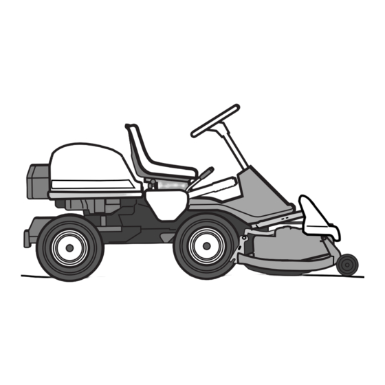
Page 9: Presentation
There is one pedal for driving forwards and one These instructions describe the Jonsered FRM 13 pedal for reversing. AUTOMATIC. This rider mower is equipped with a 12,5 horsepower Briggs &... -
Page 10: Throttle/Choke Lever
PRESENTATION Throttle and Choke lever The engine speed is adjusted with the throttle control, and thereby also the rotation speed of the blades. The control is also used to activate the choke function. When the choke is used the engine receives a richer mixture of fuel and air, which simplifies cold start. -
Page 11: Cutting Unit
PRESENTATION Cutting unit Jonsered FRM 13 AUTOMATIC is equipped with a Mulcher 90. Lift lever for cutting unit The lift lever is used to set the cutting unit in trans- port or cutting position. If the lever is pulled back the unit will lift up and the blades will automatically stop rotating (transport position). -
Page 12: Lever For Adjustment Of Cutting Height
PRESENTATION Lever for adjustment of cutting height With this lever the cutting height can be adjusted to 9 different positions. The cutting height of a Mulcher unit is 45-95 mm. Seat The seat has a jointed attachment on the front edge and can be tipped forward. -
Page 13: Driving
DRIVING • Read the safety instructions and information on the location and function of the controls before starting (see pages 3-10). • Conduct daily maintenance before starting (see maintenance schedule on page 16). Adjust the seat to the required position. Starting the engine 1. - Page 14 DRIVING Warm engine: 4. Set the throttle control midway between position 1 and 2. 5. Turn the ignition key to start position. STOP START IMPORTANT INFORMATION Do not run the starter for more than about 5 seconds at a time. If the engine does not start, wait about 10 seconds before trying again.
-
Page 15: Driving The Machine
DRIVING Driving the machine 1. Release the parking brake by pressing down the brake pedal. 2. Carefully press down one of the pedals until the correct speed is reached. To drive forwards: press down pedal (1). To reverse: press down pedal (2). 3. -
Page 16: Cutting Tips
DRIVING 4. Push in the lock button on the lift lever and lower down the cutting unit. IMPORTANT INFORMATION The service-life of the drive belts in- creases considerably if the engine is run at low speed when engaging the blades. For this reason do not increase the throt- tle until the cutting unit has been lowered to the cutting position. -
Page 17: Stopping The Engine
DRIVING WARNING! Never drive the machine on ground with a slope of more than 15°. Mow slopes upwards and downwards, never across. Avoid sudden changes in direction. MAX 15 Stopping the engine Preferably allow the engine to idle for a minute to obtain normal working temperature before stopping it if it has been working hard. -
Page 18: Maintenance
MAINTENANCE Maintenance schedule The following is a list of the maintenance which should be conducted on the machine. For the items which are not described in these instructions go to an authorised service workshop. Daily Maintenance interval mainte- in hours Maintenance Page nance... -
Page 19: Dismantling Of The Machine Hoods
MAINTENANCE Dismantling of the machine hoods Engine hood The engine is accessible for servicing when the engine hood is lifted up. Tilt the seat forward, release the rubber strap under the seat, and tilt the hood backwards. Front hood Release the clip on the front hood and lift off the fender. -
Page 20: Checking The Engine's Oil Level
MAINTENANCE Check the engine’s oil level Check the oil level in the engine when the machine is horizontal. Dismantle the engine hood as per the description on page 17. Release the dip stick and pull out. Wipe off the oil and insert again. -
Page 21: Checking And Adjusting The Steering Wires
MAINTENANCE Checking and adjustment of the steering wires The steering is controlled by means of wires. These can in time become slack, which implies that the adjustment of the steering becomes altered. Check and adjust the steering as follows: 1. Dismantle the frame-plate by releasing the screws (two on each side). -
Page 22: Checking The Transmission's Oil Level
MAINTENANCE Check the transmission’s oil level 1. Check the transmission’s oil level by removing the transmission cover. Release the two screws (one of each side) and lift off the transmission cover. 2. Unscrew the oil cap and check that the oil level lies between the markings on the dip stick. -
Page 23: Replacement Of Air Filter
MAINTENANCE Replacing the air filter If the engine seems to lack power or goes irregu- larly the reason may be that the air filter is clogged. It is therefore important to replace the air filter at regular intervals (see maintenance schedule on page 16 for correct service interval). -
Page 24: Checking And Adjustment Of Cutting Unit's Ground Pressure
MAINTENANCE Checking and adjustment of the cutting unit’s ground pressure To achieve the best cutting results the cutting unit should follow the underlying surface without press- ing too hard against it. The pressure is adjusted with a screw on each side of the machine. -
Page 25: Adjusting The Parallelism Of The Cutting Unit
MAINTENANCE Adjusting the parallelism of the cutting unit 1. Remove the front hood and right-hand fender as described on page 18. 2. Unscrew the nut (1) from the parallel strut. Remove the clip (2) and the parallel strut. 3. Turn the fork anti-clockwise to lower the rear edge of the hood, or clockwise to raise the rear edge of the hood. -
Page 26: Service Position For Cutting Unit
MAINTENANCE Service position for cutting unit The cutting head can be placed in the service position to provide easy access for cleaning, repairs and servicing. In the service position the cutting unit is raised and locked in the vertical position. Placing in service position 1. - Page 27 MAINTENANCE 4. Fit the support wheels on either side of the rear of the cutting unit. 5. Disengage the spring from the drive belt tensioning wheel. 6. Place a foot on the front edge of the cutting unit near the wheel and raise the front edge of the unit to make it easier to remove the lift strut.
- Page 28 MAINTENANCE 7. Lift off the drive belt (1). Then pull out the pin (2). Take care not to get your hand trapped. Pull the frame forwards and insert the pin. 9. Grasp the front edge of the cutting unit, pull out and raise into the service position.
-
Page 29: Lubrication
MAINTENANCE Lubrication The following two lubrication points should be regularly lubricated with high quality graphite grease. With daily use lubrication should be conducted twice a week. General lubrication All joints and bearings are lubricated on manufac- ture with molybdenum sulphide grease. Re-grease with same type of grease. -
Page 30: Changing The Oil
MAINTENANCE Changing the oil The oil should be changed for the first time after 5 hours of running time. Thereafter it should be changed every 25 hours of running time. WARNING! Engine oil can be very hot if it is drained off directly after the engine is stopped. -
Page 31: Checking And Adjustment Of Throttle Wire
MAINTENANCE Checking and adjustment of the throttle wire If the engine does not respond as it should do when the throttle lever is moved or if the top speed is not reached, the throttle wire may need adjusting. 1. Release the clamping screw (see arrow) and push the throttle control to full throttle position. -
Page 32: Trouble Shooting Schedule
TROUBLE SHOOTING SCHEDULE Problem Procedure Engine will not start. • Fuel tank empty. • Plug defective. • Plug connection defective. • Dirt in carburettor or fuel pipe. Starter does not pull round engine. • Battery flat. • Bad contact between cable and battery terminal. •... -
Page 33: Storage
STORAGE Winter storage To put the machine in order for storage follow these At the end of the season the machine should immediately be put in order for storage, also if it is instructions: going to stand idle for more than 30 days. Fuel 1. -
Page 34: Technical Data
TECHNICAL DATA Dimensions Jonsered FRM 13 AUTOMATIC Length without cutting unit 2000 mm Width without cutting unit 960 mm Height 1060 mm Service weight 245 kg including cutting unit Wheel base 820 mm Track Front 715 mm, rear 625 mm... - Page 35 We, Jonsered, S-561 82 Huskvarna, Sweden, tel. +46 36-146500, declare under sole responsibility that the rider mowers Jonsered FRM 13 AUTOMATIC from 1998’s serial numbers and onwards (the year is clearly stated in plain text on the type plate with subsequent serial number), is in conformity with the following standards or other normative documents following the provisions in the COUNCIL’S DIRECTIVES:...
- Page 36 108 87 84-26 ´*xnJ¶6y¨ 1999W51...
Need help?
Do you have a question about the FRM13 Automatic and is the answer not in the manual?
Questions and answers