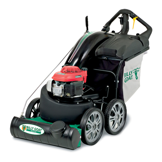
Billy Goat MV650SPH Owner's Manual
Self-propelled vacuum
Hide thumbs
Also See for MV650SPH:
- Owner's manual (34 pages) ,
- General safety and warranty (36 pages) ,
- Owner's manual (20 pages)
Table of Contents
Advertisement
Quick Links
BILLY GOAT
Self-Propelled Vacuum Owner's Manual
Accessories
Caster Kit
Use on hard surface
for maneuverability.
P/N 840129
Liner Kit
Interior housing liner
to decrease housing
wear
P/N 840201
Part No 840245
®
MV650SPH and MV600SPE
Hose Kit
For vacuuming hard
to reach areas.
P/N 840116
Bag Liner Kit
To collect leaves,
thatch, and grass.
P/N 840134
1
Felt Bag Kit
Use on all dusty
conditions.
P/N 840194
Form No F050112D
Advertisement
Table of Contents

Related Manuals for Billy Goat MV650SPH


Summary of Contents for Billy Goat MV650SPH
- Page 1 ® BILLY GOAT MV650SPH and MV600SPE Self-Propelled Vacuum Owner’s Manual Accessories Caster Kit Hose Kit Bag Liner Kit Felt Bag Kit Use on hard surface For vacuuming hard To collect leaves, Use on all dusty for maneuverability. to reach areas.
- Page 2 MV650SPH Self-Propelled Vacuum Owner’s Manual CONTENTS Specifications and Sound/Vibration ........................Instruction Labels ............................... Assembly Instructions ............................5-8 Operation ................................9-13 Maintenance and Troubleshooting ........................14-19 Illustrated Parts List ............................20-27 Go to http://www.billygoat.com for French-Canadian translations of the product manuals.
-
Page 3: Sound Data
MV650SPH Self-Propelled Vacuum Owner’s Manual MV 650 SERIES SPECIFICATIONS MV650SPH MV600SPE Engine Type Honda GSV190AA1A Briggs and Stratton 122MO70110F1 Horsepower 6.5 (4.85 kW) 6.25 (4.66 kW) Fuel Capacity 1.6 qt (1.5 L) 1qt (.9L) Oil Capacity 0.58 qt (0.54L) 0.63 qt (0.59L) Unit Weight 179 lbs (81.2 kg) - Page 4 MV650SPH Self-Propelled Vacuum Owner’s Manual INSTRUCTION LABELS ® The labels shown below were installed on your BILLY GOAT MV Vacuum. If any labels are damaged or missing, replace them before operating this equipment. Item numbers from the Illustrated Parts List and part numbers are provided for convenience in ordering replacement labels.
- Page 5 MV650SPH Self-Propelled Vacuum Owner’s Manual MV Vacuum Assembly Drawing Form No F050112D Part No 840245...
- Page 6 MV650SPH Self-Propelled Vacuum Owner’s Manual PARTS LIST Part No 840245 Form No F050112D...
-
Page 7: Assembly Instructions
MV650SPH Self-Propelled Vacuum Owner’s Manual ASSEMBLY INSTRUCTIONS ® Your BILLY GOAT MV Vacuum was shipped in one carton, completely assembled except for the Hood/Upper Handle Assembly. Mounting hardware for the Hood/Upper Handle Assembly is temporarily installed on the lower handle and the Housing assembly. - Page 8 MV650SPH Self-Propelled Vacuum Owner’s Manual 4. Attach upper handle brace to lower handle using 5. Attach rod end (164) to the nozzle door rod then corresponding hardware. Then repeat this step on the secure in place by tightening jam nut.
-
Page 9: Operation
MV650SPH Self-Propelled Vacuum Owner’s Manual OPERATION PERATOR ONTROLS The operator’s position is at the rear of the machine between the handlebars. The operator should STAND in a position to allow both handlebars to be grasped firmly, which allows sufficient leverage to steer the machine. Operator’s controls are shown below. - Page 10 MV650SPH Self-Propelled Vacuum Owner’s Manual Secure the unit with left hand at the handle then pull starter rope with right hand to start engine. On Electric PULL ROPE models only STARTER WITH RIGHT HAND SECURE UNIT AT THE HANDLE WITH LEFT HAND DURING START PULL STARTER CORD slowly until resistance is felt.
- Page 11 MV650SPH Self-Propelled Vacuum Owner’s Manual ACUUM OZZLE DJUSTMENT The vacuum nozzle door adjusts for the maximum performance under various applications. Nozzle fully opened. This is ideal for turf application Nozzle half way opened. This is ideal for hard surface application Nozzle closed for OPTIONAL hose kit.
- Page 12 MV650SPH Self-Propelled Vacuum Owner’s Manual ACUUMING PERATION 1. Move Shift Lever to correct position (1, 2, or 3) for desired gear. Gear Shift Lever 2. Squeeze the Drive Clutch lever against the handle to engage the drive. Drive Clutch Lever 1.
- Page 13 MV650SPH Self-Propelled Vacuum Owner’s Manual LEARING A LOGGED OZZLE DISCONNECT spark plug wire before servicing unit. 1. Shut engine off and wait for impeller to stop completely. 2. Disconnect spark plug wire. 3. Wearing durable gloves, remove clog. WEAR durable gloves. Clog may contain sharp materials.
- Page 14 MV650SPH Self-Propelled Vacuum Owner’s Manual MAINTENANCE ERIODIC AINTENANCE Periodic maintenance should be performed at the following intervals: Maintenance Operation Every Daily or Every Every 25 Every 50 Every 100-150 5 Hours Hours Hours Hours Inspect for worn or damaged parts.
- Page 15 MV650SPH Self-Propelled Vacuum Owner’s Manual MPELLER EMOVAL READ all safety instructions before servicing unit. DISCONNECT spark plug wire before servicing unit. Tools required: 1/2” socket, 3/8” drive ratchet, 3/8” drive extension, 3/8” drive universal joint, 3/8” drive pry bar or long screwdriver jack stands or similar device adequate to support weight of machine.
- Page 16 MV650SPH Self-Propelled Vacuum Owner’s Manual Procedure: 1. Wait for engine to cool and DISCONNECT SPARK PLUG! 2. Engage the clutch lever then pull the unit back until it stops freewheeling. The clutch lever should engage around 2 5/16” of travel or 4 inches from tip of lever to handle.
- Page 17 MV650SPH Self-Propelled Vacuum Owner’s Manual NSTALLING RIVE HAIN LIGNMENT ENSION READ all safety instructions before servicing unit. DISCONNECT spark plug wire before servicing unit. Tools required: 7/16” and 1/2” socket. 7/16” and 1/2” combination wrench. “Needle nose” pliers Flat head screwdriver Allow the engine to cool completely and DISCONNECT THE SPARK PLUG.
-
Page 18: Charging The Battery
MV650SPH Self-Propelled Vacuum Owner’s Manual IRING IAGRAMS Bag Switch Circuit Schematic Diagram Battery Care (For Electric-Starting Models) Proper care can extend the life of a battery. Follow these recommendations to ensure your battery’s best performance and long life: • Do not allow the battery charge to get too low. If the machine is not used, charge the battery every 4 – 6 weeks. -
Page 19: Troubleshooting
MV650SPH Self-Propelled Vacuum Owner’s Manual TROUBLESHOOTING Problem Possible Cause Solution Will not vacuum or has poor vacuum · Dirty or full debris bag or filter. · Clean debris bag and filter. Shake bag clean or performance. wash. · Nozzle height set too high or too low. -
Page 20: Illustrated Parts List
MV650SPH Self-Propelled Vacuum Owner’s Manual ILLUSTRATED PARTS LIST Nozzle Assembly Figure 1 Part No 840245 Form No F050112D... - Page 21 MV650SPH Self-Propelled Vacuum Owner’s Manual Nozzle Assembly Parts List PART MV650SPH MV600SPE ITEM NO. NUMBER DESCRIPTION QTY. QTY. 350127 YOKE 1/2 - 20 350128 PIN YOKE 1/2" 840243 SCREWCAP BUTTON HEAD 3/8"-16 X 1 1/4" PL 8172009 WASHER 3/8" SAE ZP...
- Page 22 MV650SPH Self-Propelled Vacuum Owner’s Manual Drive /Rear Axle Assembly Figure 2 Part No 840245 Form No F050112D...
- Page 23 MV650SPH Self-Propelled Vacuum Owner’s Manual Drive /Rear Axle Assembly Parts List PART MV650SPH MV600SPE ITEM NO. NUMBER DESCRIPTION QTY. QTY. 840110 BRACKET TRANS MOUNT WA MV VAC 350133 BEARING 3/4" W/PILLOW BLOCK 840009 DIFFERENTIAL 54 TOOTH D-CUT 840086 BRACKET TRANS ANTI ROTATION MV 840010 GUARD DRIVE SP VAC 840085 TRANSMISSION 3 SPD GENERAL TRANS.
- Page 24 MV650SPH Self-Propelled Vacuum Owner’s Manual Engine Assembly Figure 3 Part No 840245 Form No F050112D...
- Page 25 MV650SPH Self-Propelled Vacuum Owner’s Manual Engine Assembly Parts List ITEM PART MV650SPH MV600SPE NUMBER DESCRIPTION QTY. QTY. 840069 ENGINE HONDA 6.5 VERTICAL GSV190 840239 ENGINE BRIGGS 6 ELEC START 840136 IMPELLER ASSEMBLY SP MV VAC 840107 PLATE TOP WA SP MV VAC...
- Page 26 MV650SPH Self-Propelled Vacuum Owner’s Manual Hood Assembly Figure 4 Part No 840245 Form No F050112D...
- Page 27 MV650SPH Self-Propelled Vacuum Owner’s Manual Hood Assembly ITEM PART MV650SPH MV600SPE NUMBER DESCRIPTION QTY. QTY. 840045 CONTROL THROTTLE WESCON MV VAC 840023 CONTROL SHIFT WESCON MV VAC 840063 CONTOL LEVER ASSY CLUTCH SP VAC 500176 LABEL CLUTCH DRIVE 840141 HOOD ASSY W/ LABEL MV VAC...
Need help?
Do you have a question about the MV650SPH and is the answer not in the manual?
Questions and answers