Yamaha Portatone PSR-740 Service Manual
Hide thumbs
Also See for Portatone PSR-740:
- Service manual (18 pages) ,
- Manual de instrucciones (188 pages) ,
- Owner's manual (188 pages)
Table of Contents
Advertisement
PK
001627
PSR-740 19990901-160000
PSR-640 19990901-120000
SERVICE MANUAL
CONTENTS
Psr-740 Midi Implementation Chart ......................... 49
Psr-640 Midi Implementation Chart ......................... 50
OVERALL CIRCUIT DIAGRAM
.............................................. 3/4
...................................... 5
................. 8
............................. 10
............................... 14
.................................. 19
........................................ 20
............................. 25/27
.......................................... 29
................... 30/32
................. 34
HAMAMATSU, JAPAN
1.82K-9201
Printed in Japan '99.08
PSR-740
PSR-640
.... 6
.... 7
Advertisement
Table of Contents

Related Manuals for Yamaha Portatone PSR-740


Summary of Contents for Yamaha Portatone PSR-740
- Page 1 SERVICE MANUAL PSR-740 PSR-640 CONTENTS SPECIFICATIONS ..........3/4 PANEL LAYOUT ........5 PSR-740 BLOCK DIAGRAM ..6 PSR-640 BLOCK DIAGRAM ..7 CIRCUIT BOARD LAYOUT ....8 DISASSEMBLY PROCEDURE ......10 LSI PIN DESCRIPTION ....... 14 IC BLOCK DIAGRAM ........19 CIRCUIT BOARDS ........
- Page 2 IMPOR TANT NOTICE This manual has been provided for the use of authorized Yamaha Retailers and their service personnel. It has been assumed that basic service procedures inherent to the industry, and more specifically Yamaha Products, are already known and under- stood by the users, and have therefore not been restated.
-
Page 3: Specifications
• 24W • Accompaniment Freeze Voice Power Supply PSR-740 Disk Operations • Adaptor : Yamaha PA-6 power adaptor • 267 Panel Voices +13 Drum Kits + 480 • Song playback/recording Rated Voltage DC 10-12V XG Voices + 1 Organ Voice Rated Current •... - Page 4 PSR-740/PSR-640...
-
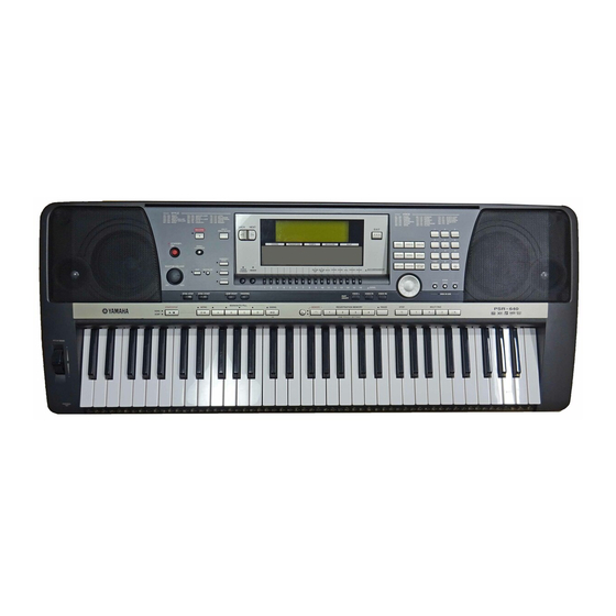
Page 5: Panel Layout
PSR-740/PSR-640 PANEL LAYOUT DISK Top Panel Controls SAVE button PSR-740 STANDBY/ON switch LOAD button MASTER VOLUME control UTILITY button DEMO/LANGUAGE button !8 #0 SYNC STOP button BACK NEXT E X I T HELP/DIRECT ACCESS button SYNC START button ACMP ON/OFF button INPUT VOLUME control FINGERING button !4 !5... -
Page 6: Psr-740 Block Diagram
PSR-740/PSR-640 PSR-740 BLOCK DIAGRAM IC16 IC33 IC17 IC29 IC21 IC19 IC18 IC20 1 3 5 7 20 21 40 10 13 14 37 17-19 21 IC24 IC11 IC12 IC13 94,96 IC15 11 13 32 11 13 32 22 24 29 IC14 IC15 IC23... -
Page 7: Psr-640 Block Diagram
PSR-740/PSR-640 PSR-640 BLOCK DIAGRAM IC420 TR501-505 IC530 IC800 IC400 IC510 IC500 IC430 IC410 10 13 14 37 1 3 5 7 20 21 40 IC190 IC350 IC310 IC320 IC300 IC330 IC100 11 13 32 11 13 32 22 24 29 13 14 31 30 IC360 IC360... - Page 8 PSR-740/PSR-640 CIRCUIT BOARD LAYOUT...
- Page 9 PSR-740/PSR-640 REF. CONNECTOR PIN/ DESTINATION PART NO. REMARKS ASSEMBLY LENGTH q q q q q MIC JACK-CN2 DM-CN3 MICJ-DM V386730 PSR-740only w w w w w MIC JACK-CN1 MIC-CN1 MICJ-SH V386740 PSR-740only e e e e e MIC-CN2 DM-CN15 MICSH-DM V386750 PSR-740only r r r r r...
-
Page 10: Disassembly Procedure
PSR-740/PSR-640 DISASSEMBLY PROCEDURE Lower Case Assembly Remove the sixteen (16) screws marked [260] and the two (2) screws marked [270A]. The lower case assembly can then be removed. (Fig.1) [ 260 ] [ 260 ] [ 270A ] [ 260 ] [ 260 ] [ 260 ] [260]:... -
Page 11: Upper Case Side
PSR-740/PSR-640 Speakers(Tweeter) Upper case side [240A] [250A] [240A] [250A] [240B] Remove the lower case assembly. (See procedure 1.) Remove the four (4) screws marked [240G]. The right and left speakers(tweeter) can then be removed. (Fig.3) [250C] [250C] [240B] [250A] [250A] Keyboard Assembly Shield cover L Remove the lower case assembly. - Page 12 PSR-740/PSR-640 LCD(U) and LCD(L) FDD holder L [ 40 ] 11-1 Remove the lower case assembly. (See procedure 1.) 11-2 Remove the DM circuit board. (See procedure 2.) 11-3 Remove the one (1) screw marked [240H]. The FDD holder R shield cover U can then be removed.
- Page 13 PSR-740/PSR-640 Assembling the keyboard assembly 17-1 Install the white keys CEGB from the lower notes, and then install the DFA keys and C' key. Afterwards install the black keys from the higher notes, and tighten the twenty- one (21) screws marked [140]. (Fig.8) 17-2 Install the rubber contacts in the assembly while pressing the keys as shown in Figure 9.
-
Page 14: Lsi Pin Description
PSR-740/PSR-640 LSI PIN DESCRIPTION SH-7043A (XW485100) CPU SH-7043 (XW180100) CPU NAME FUNCTION NAME FUNCTION /WRHH/PA23 HH write/Port A DACK0/PE14 DMA transfer strobe/Port E Data bus /WRHL/PA22 HL write/Port A /CASHH/PA21 HH Column address strobe/Port A DACK1/PE15 DMA transfer strobe/Port E Power supply... - Page 15 PSR-740/PSR-640 HG73C205AFD (XU947C00) SWX00B TONE GENERATOR NAME FUNCTION NAME FUNCTION Initial clear CMA3 Program address bus RFCLKI PLL Clock CMA8 Program address bus PLL Control CMA2 Program address bus AVDD_PLL Power supply read signal AVSS_PLL Ground CMA1 Program address bus MODE0 SWX dual mode high byte effective signal...
- Page 16 PSR-740/PSR-640 TC203C760HF-002 (XS725A00) SWP30B (AWM Tone Generator coped with MEG) Standard Wave Processor NAME FUNCTION NAME FUNCTION (Ground) (Ground) HMD0 HMD1 HMD2 HMD3 HMD4 HMD5 Address bus internal register HMD6 HMD7 Wave memory data bus (Upper data memory) HMD8 HMD9 CA10 HMD10 CA11...
- Page 17 PSR-740/PSR-640 YSS236-F (XT013A00) VOP3 NAME FUNCTION NAME FUNCTION Power supply WA17 Serial output WA16 WA15 Ground WA14 Power supply External memory address bus WA13 WA12 WA11 Serial output WA10 Ground Power supply WDCK Data enable for DAC WA09 SWPKON SWP00 format key on output WA08 IRQN EG interrupt...
- Page 18 PSR-740/PSR-640 HD63B05V0F073P (XR951A00) CPU NAME FUNCTION NAME FUNCTION /RES Reset /INT Interrupt request Non-maskable interrupt Port C Port A ...
-
Page 19: Ic Block Diagram
PSR-740/PSR-640 IC BLOCK DIAGRAM SN74HCU04NSR (XC723A00) SN74HC08NSR (XD831A00) TC74HC32AF (XN241A00) SN74HCU04N (IG142250) HD74LVC08FP (XU720A00) Quad 2 Input OR HD63266F (XI939A00) FDC (Floppy Disk Controller) Hex Inverter Quad 2 Input AND DM: IC14(PSR-740) IC360(PSR-640) IC10,16(PSR-740) IC420(PSR-640) DM: IC15(PSR-740) IC370(PSR-640) NAME FUNCTION NAME FUNCTION JACK: IC02... -
Page 20: Circuit Boards
PSR-740/PSR-640 CIRCUIT BOARDS DM Circuit Board (PSR-740) TR1 installation Bind head tapping screw-B 3.0 X 8 (EP600190) Component side Note: See parts list for details of circuit board component parts. 2NA-V320040-1... - Page 21 PSR-740/PSR-640 DM Circuit Board 〈 PSR-740 〉 AM (AM) Circuit Board AM (HP) Circuit Board Component side AM (PSW) Circuit Board Component side AM (VR) Circuit Board MASTER VOLUME Component side Component side IC710 Installation IC310 Installation Pattern side Bind head tapping screw-B Bind head tapping screw-B Grease 3.0 X 10 (EP600220) 2pcs...
- Page 22 PSR-740/PSR-640 DM Circuit Board 〈 PSR-640 〉 Component side Pattern side 2NA-V350510-1,2...
- Page 23 PSR-740/PSR-640 PN (PN3) Circuit Board PN (PN4) Circuit Board PN (ENC) Circuit Board PN (PN2) Circuit Board Data dial : PSR-740 only PN (PN1) Circuit Board Component side Component side Component side Component side PN (WH1) Circuit Board 〈 PSR-640 〉 PN (WH2) Circuit Board 〈...
- Page 24 PSR-740/PSR-640 JACK Circuit Board INV Circuit Board MIC Circuit Board MIC-JACK Circuit Board 〈 PSR-740 only 〉 〈 PSR-740 only 〉 AUX OUT FOOT VOLUME TO HOST Mac/PC1/PC2/MIDI MIDI IN MIDI OUT FOOT SW. L/L+R DC-IN INPUT VOL Component side MIC/LINE IN Component side Component side...
-
Page 25: Test Program
PSR-740/PSR-640 TEST PROGRAM A. PREPARATION 1) PA-6 (AC adaptor) is used. 2) The volume is usually moved to the use position when no volume change is required. 3) Measuring instruments: frequency counter, level meter (with JIS-C filter) Note: Connect a stereo plug to the [PHONES] jack at 33 ohms. 4) Jigs: foot switch, MIDI cable, floppy disk (2HD &... - Page 26 PSR-740/PSR-640 015: Output L Connect the level meter (with a JIS-C filter) to the [PHONES] jack. (33 ohm load) Set the [MASTER VOLUME] at maximum and check the output level (1 kHz). PHONES L: -8.0 dBm +/- 2 dB PHONES R: less than -50.0 dBm Connect the monaural plugs of the level meter (with a JIS-C filter) to the [AUX OUT] jacks.
- Page 27 PSR-740/PSR-640...
- Page 28 PSR-740/PSR-640...
-
Page 29: Data Initialization
PSR-740/PSR-640 DATA INITIALIZATION CAUTION All data can be initialized and restored to the factory preset condition by turning on the power • All registration and User while holding the highest (rightmost) white key on the keyboard. “Now initializing the internal Style/Pad memory data, memory...”... -
Page 30: Alert Message List
PSR-740/PSR-640 ALERT MESSAGE LIST The disk contains no file to be loaded, copied, or be deleted. No file on disk! Insert the disk that contains files to be loaded, copied, or deleted. Insert another disk. An unformatted disk is inserted. Unformatted disk! An error occurred during execution of a disk operation. - Page 31 PSR-740/PSR-640 This message appears when executing the Quantize or Recording Memory full! operations (in the Style Recording mode) when the internal memory is full. Clear unnecessary data. This message appears when you attempt to edit, quantize or clear the Data not found! track which contains no data in the Record mode.
- Page 32 PSR-740/PSR-640...
- Page 33 PSR-740/PSR-640...
-
Page 34: Midi Data Format
PROGRAM CHANGE 0001 0100 0101 0100 PITCH BEND CHANGE 0001 0101 0101 0101 SYSTEM EXCLUSIVE MESSAGE 0001 0110 0101 0110 <YAMAHA MIDI FORMAT> 0001 0111 0101 0111 <UNIVERSAL> 0001 1000 0101 1000 UNIVERSAL NON-REALTIME F0H 7EH..F7H 0001 1001 0101 1001 <XG STANDARD>... - Page 35 PARAMETER NUMBER” PITCH BEND CHANGE * Receive CONTROL NUMBER. SYSTEM EXCLUSIVE MESSAGE c = 0 BANK SELECT MSB ; v = 0:XG NORMAL, <YAMAHA MIDI FORMAT> 64:SFX NORMAL, <UNIVERSAL> 126:XG SFX KIT, UNIVERSAL REALTIME F0H 7FH..F7H 127:XG DRUM UNIVERSAL NON-REALTIME F0H 7EH..F7H...
- Page 36 (3-2-7) POLY (Receive only) (CONTROL NUMBER = 7FH , DATA VALUE = 0) (3-6) SYSTEM EXCLUSIVE MESSAGE Same processing as for All Sounds Off and the corresponding channel will be changed to Mode (3-6-1) YAMAHA MIDI FORMAT (3-3) REGISTERED PARAMETER NUMBER (RPN) (3-6-1-1) SECTION CONTROL...
- Page 37 For more information on Address and Parameters, refer to < Table 1-2 > - < Table 1-8 >. 11110000 Exclusive status 01000011 YAMAHA ID The data types listed below are transmitted and received. 01111110 Style System Data 00000000...
- Page 38 (3-6-5-3) Vocal Harmony Pitch to Note Part (PSR-740 ONLY) binary hexadecimal (3-6-4-1) DOC MULTI TIMBRE ON / OFF (Receive only) 11110000 Exclusive status binary hexadecimal 01000011 YAMAHA ID 11110000 Exclusive status 01110011 Clavinova ID 01000011 YAMAHA ID 00000001 Clavinova common ID...
- Page 39 PSR-740/PSR-640 < Table 1-1> Parmeter Basic Address Parameter Change Address (H) (M) (L) Description SYSTEM System Drum Setup Reset XG System On All Parameter Reset INFORMATION System Information EFFECT 1 Effect1(Reverb,Chorus,Variation) MULTI EQ Multi EQ(PSR-740 ONLY) EFFECT 2 Effect2(PSR-740 ONLY) SPECIAL EFFECT Special Effect2(PSR-740 ONLY) MULTI PART...
- Page 40 PSR-740/PSR-640 Address Size Data Prameter Name Description Default Value 00..7F Variation Type MSB Refer to the Ef. Type List 05(=DELAY L,C,R) 00..7F Variation Type LSB 00 : basic type 00..7F Vari. Param. 1 MSB Refer to the Ef. Parameter List Depend on Vari.
- Page 41 PSR-740/PSR-640 Address Size Data Prameter Name Description Default Value 00..7F Ins. Param.1 MSB Refer to the Ef. Parameter List Depend on Insertion Type 00..7F Ins. Param.1 LSB Refer to the Ef. Parameter List Depend on Insertion Type 00..7F Ins. Param.2 MSB Refer to the Ef.
- Page 42 PSR-740/PSR-640 Address Size Data Prameter Name Description Default Value 28..58 MW Pitch Control -24..+24[semitones] 00..7F MW Filter Control -9600..+9450[cent] 00..7F MW Amp. Control -100..+100[%] 00..7F MW LFO PMod Depth 0..127 00..7F MW LFO FMod Depth 0..127 00..7F MW LFO AMod Depth 0..127 28..58 Bend Pitch Control...
- Page 43 PSR-740/PSR-640 < Table 1-11 > Effect Type List XG ESSENTIAL EFFECT Same as LSB=0 XG OPTION EFFECT XG OPTION EFFECT(Only PSR-740) Expanded type for PSR-740/640 * If the received value does not contain an effect type in the TYPE LSB, the LSB will be directed to TYPE 0. * Panel Effects are based on the “[Number] Effect Name”.
- Page 44 PSR-740/PSR-640 VARIATION TYPE (0-63) (PSR-740) TYPE MSB TYPE LSB 03...07 09...15 NO EFFECT [1]HALL1 [5]HALL2 [2]HALL2 [3]HALL3 [4]HALL4 [10]ROOM1 [11]ROOM2 [12]ROOM3 [6]ROOM1 [7]ROOM2 [8]ROOM3 [9]ROOM4 [15]STAGE1 [16]STAGE2 [13]STAGE1 [14]STAGE2 [19]PLATE [17]PLATE1 [18]PLATE2 [21]DELAY L,C,R [20]Delay LCR [22]DELAY L,R [23]ECHO [24]CROSS DELAY [25]ER1 [26]ER2 [27]GATE REVERB...
- Page 45 PSR-740/PSR-640 EARLY REF1,EARLY REF2(variation block) < Table 1-12 > Effect Parameter List Parameter Display Value See Table Comment Control Type S-H, L-H, Rdm, Rvs, Plt, Spr HALL1,HALL2, ROOM1,ROOM2,ROOM3, STAGE1,STAGE2, PLATE (reverb, variation, insertion block) Room Size 0.1-7.0 0-44 table#6 Parameter Display Value See Table...
- Page 46 PSR-740/PSR-640 AMBIENCE (variation block) DISTORTION, OVERDRIVE (variation, insertion block) Parameter Display Value See Table Comment Control Parameter Display Value See Table Comment Control Delay Time 0.0mS-50mS 0-127 table#2 Drive 0-127 0-127 Output Phase normal/invers EQ Low Frequency 32Hz-2.0kHz 4-40 table#3 PSR-740 50Hz-2.0kHz 8-40...
- Page 47 PSR-740/PSR-640 TOUCH WAH 1 (variation, insertion block), TOUCH WAH+DIST (variation block) NO EFFECT (reverb, chorus, variation block), THRU (variation, insertion block) Parameter Display Value See Table Comment Control Parameter Display Value See Table Comment Control Sensitive 0-127 0-127 Cutoff Frequency Offset 0-127 0-127 Resonance...
- Page 48 PSR-740/PSR-640 < Table 1-13 > Effect Data Value Assign Table Table#1 Table#4 Table#7 Table#11 LFO Frequency Reverb time Delay Time(400.0ms) Reverb Width;Depth;Height Data Value Data Value Data Value Data Value Data Value Data Value Data Value Data Value Data Value Data Value Data Value...
-
Page 49: Psr-740 Midi Implementation Chart
PSR-740/PSR-640 PSR-740 MIDI IMPLEMENTATION CHART [Portable Keyboard] Date :3-MAR-1999 MIDI Implementation Chart Model : PSR-740 Version : 1.0 Function... Transmitted Recognized Remarks Basic Default 1 - 16 1 - 16 Channel Changed 1 - 16 1 - 16 Default Mode Messages Altered **************... -
Page 50: Midi Implementation Chart
PSR-740/PSR-640 PSR-640 MIDI IMPLEMENTATION CHART [Portable Keyboard] Date :3-MAR-1999 MIDI Implementation Chart Model : PSR-640 Version : 1.0 Function... Transmitted Recognized Remarks Basic Default 1 - 16 1 - 16 Channel Changed 1 - 16 1 - 16 Default Mode Messages Altered **************... -
Page 51: Parts List
PARTS LIST CONTENTS PSR-740 OVERALL ASSEMBLY ........2 PSR-640 OVERALL ASSEMBLY ........4 UPPER CASE ASSEMBLY ..........6 LOWER CASE ASSEMBLY ..........8 KEYBOARD ASSEMBLY ............9 ELECTRICAL PARTS ............... 10 Notes : DESTINATION ABBREVIATIONS A : Australian model M : South African model B : British model O : Chinese model C : Canadian model... - Page 52 PSR-740/PSR-640 PSR-740 OVERALL ASSEMBLY Music rest Upper case assembly: See page 6. (PSW) 050 (VR) (AM) Keyboard assembly: See page 9. (HP) Lower case assembly: See page 8.
- Page 53 PSR-740/PSR-640 PART NO. DESCRIPTION REMARKS REF NO. RANK OVERALL ASSEMBLY PSR-740 Upper Case Assembly V 3 8 6 7 0 0 0 Shield Cover U V 3 2 0 0 4 0 0 Circuit Board V 3 8 6 7 7 0 0 Shield Cover L V 3 8 6 6 0 0 0 Circuit Board...
-
Page 54: Overall Assembly
PSR-740/PSR-640 PSR-640 OVERALL ASSEMBLY Music rest Upper case assembly: See page 7. 050 (VR) 050 (AM) (PSW) Keyboard assembly: See page 9. 050 (HP) Lower case assembly: See page 8. - Page 55 PSR-740/PSR-640 PART NO. DESCRIPTION REMARKS REF NO. RANK OVERALL ASSEMBLY PSR-640 (V387480) Upper Case Assembly (V387680) V 3 8 7 6 9 0 0 Shield Cover U V 3 5 0 5 1 0 0 Circuit Board V 3 8 7 7 0 0 0 Shield Cover L V 3 5 0 5 0 0 0 Circuit Board...
- Page 56 PSR-740/PSR-640 UPPER CASE ASSEMBLY • PSR-740 Upper case sub assembly 010d 050 (WH3) 100b (WH2) 010b 100a 010e 010c Wheel assembly 010a (PN4) (PN3) (PN2) (PN1) (ENC)
- Page 57 PSR-740/PSR-640 • PSR-640 PART NO. DESCRIPTION REMARKS REF NO. RANK UPPER CASE ASSEMBLY PSR-740/PSR-640 Upper Case Assembly PSR-740 (V386690) Upper Case Assembly PSR-640 (V387680) V 3 8 6 7 8 0 0 Upper Case Sub Assembly PSR-740 V 3 8 7 7 8 0 0 Upper Case Sub Assembly PSR-640 Upper case sub assembly...
- Page 58 PSR-740/PSR-640 LOWER CASE ASSEMBLY PART NO. DESCRIPTION REMARKS REF NO. RANK LOWER CASE ASSEMBLY PSR-740/PSR-640 (V386710) V 3 8 6 9 4 0 0 Lower Case Sub Assembly V 4 6 3 9 4 0 0 Circuit Board JACK Floppy Disk Drive Assembly (V388290) VT366600 Cover, FDD...
- Page 59 PSR-740/PSR-640 KEYBOARD ASSEMBLY 60 60b Circuit board assembly PART NO. DESCRIPTION REMARKS REF NO. RANK V 2 6 9 4 6 0 0 KEYBOARD ASSEMBLY 16M C61 MKS3 PSR-740/PSR-640 EP630220 Bind Head Tapping Screw-P 3.0X8 MFZN2BL VU328600 Frame C61 16M VH1809C0 White Keys CEGBDFA...
-
Page 60: Electrical Parts
PSR-740/PSR-640 ELECTRICAL PARTS PART NO. DESCRIPTION REMARKS REF NO. RANK ELECTRICAL PARTS PSR-740/640 V 3 8 6 6 0 0 0 Circuit Board PSR-740 (XV859B0) V 3 5 0 5 0 0 0 Circuit Board PSR-640 (XV859B0) V 3 2 0 0 4 0 0 Circuit Board PSR-740 (XW116B0) - Page 61 PSR-740/PSR-640 PART NO. DESCRIPTION REMARKS REF NO. RANK C0412 UR837470 Electrolytic Cap. 47.00 16.0V C0501 UN837100 Electrolytic Cap.-BP 10.00 16.0V C0502 UN837100 Electrolytic Cap.-BP 10.00 16.0V C0503 FG652100 Ceramic Capacitor-SL 100P 50V J C0504 FG652100 Ceramic Capacitor-SL 100P 50V J C0505 UR837100 Electrolytic Cap.
- Page 62 PSR-740/PSR-640 PART NO. DESCRIPTION REMARKS REF NO. RANK R0105 HF756220 Carbon Resistor 2.2K 1/4 J R0106 HF756220 Carbon Resistor 2.2K 1/4 J R0202 HF756330 Carbon Resistor 3.3K 1/4 J R0203 HF757220 Carbon Resistor 22.0K 1/4 J R0204 HF754100 Carbon Resistor 10.0 1/4 J R0205 HF757220...
- Page 63 PSR-740/PSR-640 PART NO. DESCRIPTION REMARKS REF NO. RANK R0604 HF756220 Carbon Resistor 2.2K 1/4 J PSR-640 R0605 HF756220 Carbon Resistor 2.2K 1/4 J R0701 HF757470 Carbon Resistor 47.0K 1/4 J R0702 HF757470 Carbon Resistor 47.0K 1/4 J R0703 HF757180 Carbon Resistor 18.0K 1/4 J R0704 HF757180...
- Page 64 PSR-740/PSR-640 PART NO. DESCRIPTION REMARKS REF NO. RANK C0049 UB012470 Monolithic Ceramic Cap. B 470P 50V K C0050 UB051270 Monolithic Ceramic Cap. SL 27P 50V J C0051 UB051270 Monolithic Ceramic Cap. SL 27P 50V J C0052 UB044100 Monolithic Ceramic Cap. F 0.010 50V Z C0053 UB044100...
- Page 65 PSR-740/PSR-640 PART NO. DESCRIPTION REMARKS REF NO. RANK C0162 UB044100 Monolithic Ceramic Cap. F 0.010 50V Z C0163 UR837100 Electrolytic Cap. 10.00 16.0V C0164 UR837100 Electrolytic Cap. 10.00 16.0V C0165 UB013100 Monolithic Ceramic Cap. B 1000P 50V K C0166 UR837100 Electrolytic Cap.
- Page 66 PSR-740/PSR-640 PART NO. DESCRIPTION REMARKS REF NO. RANK IC032 XU829A00 PCM1716E IC033 XV117A00 M5223AFP OP AMP L0001 VN381200 Coil SNT-D20TF 10uH L0002 VQ724900 Chip Inductance BK2125HM601-T -0011 VQ724900 Chip Inductance BK2125HM601-T L0012 VZ060700 Choke Coil 220U ELC15E221 15E L0013 VR243700 Chip Inductance 56U LEM2520 T 560J L0014...
- Page 67 PSR-740/PSR-640 PART NO. DESCRIPTION REMARKS REF NO. RANK -0099 RD254470 Carbon Resistor (chip) 47.0 0.1 J R0100 RD257100 Carbon Resistor (chip) 10.0K 0.1 J R0101 RD255220 Carbon Resistor (chip) 220.0 0.1 J -0108 RD255220 Carbon Resistor (chip) 220.0 0.1 J R0109 RD257150 Carbon Resistor (chip)
- Page 68 PSR-740/PSR-640 PART NO. DESCRIPTION REMARKS REF NO. RANK C0205 UB052100 Monolithic Ceramic Cap. SL 100P 50V J C0208 UB051220 Monolithic Ceramic Cap. SL 22P 50V J C0209 UB051220 Monolithic Ceramic Cap. SL 22P 50V J C0210 UR828100 Electrolytic Cap. 100.00 10.0V C0221 UB044100 Monolithic Ceramic Cap.
- Page 69 PSR-740/PSR-640 PART NO. DESCRIPTION REMARKS REF NO. RANK C0802 UR828100 Electrolytic Cap. 100.00 10.0V C0803 UB044100 Monolithic Ceramic Cap. F 0.010 50V Z C0901 UB044100 Monolithic Ceramic Cap. F 0.010 50V Z C0902 UR848100 Electrolytic Cap. 100.00 25.0V C0903 UR839100 Electrolytic Cap.
- Page 70 PSR-740/PSR-640 PART NO. DESCRIPTION REMARKS REF NO. RANK R0121 RD257470 Carbon Resistor (chip) 47.0K 0.1 J R0122 RD257470 Carbon Resistor (chip) 47.0K 0.1 J R0125 RD257470 Carbon Resistor (chip) 47.0K 0.1 J -0128 RD257470 Carbon Resistor (chip) 47.0K 0.1 J R0131 RD257470 Carbon Resistor (chip)
- Page 71 PSR-740/PSR-640 PART NO. DESCRIPTION REMARKS REF NO. RANK X0801 V 3 8 1 1 5 0 0 Ceramic Resonator 16.00M CSTCV16.0 ZD911 VU172000 Zener Diode UDZS5.6BTE-17 5.6V V 4 2 0 0 4 0 0 Circuit Board (XW193B0) VA078900 Jumper Wire 0.55 C0001 V 4 0 0 7 8 0 0...
- Page 72 PSR-740/PSR-640 PART NO. DESCRIPTION REMARKS REF NO. RANK R011 HF757100 Carbon Resistor 10.0K 1/4 J -014 HF757100 Carbon Resistor 10.0K 1/4 J R015 HF755220 Carbon Resistor 220.0 1/4 J R016 HF755220 Carbon Resistor 220.0 1/4 J R017 HF755100 Carbon Resistor 100.0 1/4 J R018 HF755100...
- Page 73 PSR-740/PSR-640 PART NO. DESCRIPTION REMARKS REF NO. RANK VK025600 Wire Trap 52147 12P TE VK024900 Wire Trap 52147 5P TE V 2 4 0 4 9 0 0 Circuit Board MKS3 (XU878B0) Vibration-proof Tape 10X64X0.5 (VK34680) VA078900 Jumper Wire 0.55 ...
- Page 74 PSR-740/PSR-640 PART NO. DESCRIPTION REMARKS REF NO. RANK LD020 VT425100 SLZ-190B-17-T1 RE VOICE R2 LD021 VD180000 SLZ-190B-03 RE MAIN D LD023 VT425100 SLZ-190B-17-T1 RE PSR-740 FAST/SLOW LD024 VT425100 SLZ-190B-17-T1 RE TOUCH LD030 VT425100 SLZ-190B-17-T1 RE VOICE R1 LD031 VD180000 SLZ-190B-03 RE ENDING 2 LD033 VT425100...
- Page 75 PSR-740/PSR-640 PART NO. DESCRIPTION REMARKS REF NO. RANK SW503 VV056000 Tact Switch SKQNAE025A STYLE,6,PAD4,VOICE L, -508 VV056000 Tact Switch SKQNAE025A MAIN B,FREEZE SW509 VV056000 Tact Switch SKQNAE025A PSR-740 INTRO1 SW510 VV056000 Tact Switch SKQNAE025A DEMO SW511 VV056000 Tact Switch SKQNAE025A PSR-740 MASTER EQ SW600 VV056000...
- Page 76 PSR-740 PSR-740 CIRCUIT DIAGRAM (DM1/2, MKS3, MKH, MKL, INV) MKS3 28CC1-8811360 28CC1-8812655 28CC1-8811360 DECODER SRAM 1M INVETER to PN1-CN8 EPROM MAIN1 32M D-FF TRANSISTOR ARRAY Ceramic Capacitor to PN1-CN2 DRAM 4M : Mylar Capacitor to JACK-JK5 : Metal Oxide Film Resistor EPROM MAIN2 32M Note : See parts list for details of circuit board component parts...
- Page 77 PSR-740 PSR-740 CIRCUIT DIAGRAM (DM2/2, MIC-JACK, MIC) LED DRIVER INVERTER WAVE ROM LL 32M WAVE ROM LH 16M (RE) (GR) 0P AMP 560P INVERTER SWP30B WAVE ROM HH 16M WAVE ROM HL 32M 4.7K 5600p 0P AMP REGULATOR +3.3V 28CC1-8814266 DRAM 4M OP AMP OP AMP...
- Page 78 PSR-640 PSR-640 CIRCUIT DIAGRAM (DM, MKS3, MKH, MKL, INV) MKS3 28CC1-8811360 28CC1-8812655 28CC1-8811360 DECODER RESET D-FF to PN1-CN2 DECODER DECODER to PN1-CN8 PROGRAM1 ROM H 32M SRAM 1M TRANSISTOR ARRAY DECODER to PN1-CN1 to JACK-JK5 DRAM 16M TRANSISTOR ARRAY L C D D - FF PROGRAM2 ROM L32M SRAM 256K...
- Page 79 PSR-740 / PSR-640 PSR-740 / PSR-640 OVERALL CIRCUIT DIAGRAM (AM, HP, P.SW, VR, JACK, PN1, PN2, PN3, PN4, WH1, WH2, WH3, ENC) FOOT SWITCH REGULATOR +9V FOOT VOLUME to DM - CN2 EQUALIZER (PSR-740) to DM - CN910 (PSR-640) P.SW C101 28CC1-8813198 EQUALIZER...
Need help?
Do you have a question about the Portatone PSR-740 and is the answer not in the manual?
Questions and answers