Mitsubishi Electric MSZ-A09NA Service Manual
Split-type indoor unit
Hide thumbs
Also See for MSZ-A09NA:
- Service manual (49 pages) ,
- Operating instructions manual (32 pages) ,
- Installation manual (9 pages)
Table of Contents
Advertisement
SPLIT-TYPE AIR CONDITIONERS
INDOOR UNIT
SERVICE MANUAL
Models
MSZ-A09NA, -
MSZ-A12NA, -
MSZ-A15NA, -
MSZ-A17NA, -
MSZ-A24NA, -
MSY-A15NA, -
MSY-A17NA, -
MSY-A24NA, -
NOTE:
RoHS compliant products have <G> mark on the spec name plate.
For servicing of RoHS compliant products, refer to the PARTS
LIST (RoHS compliant).
1
1
1
1
1
1
1
1
CONTENTS
1. TECHNICAL CHANGES ··································· 3
2. PART NAMES AND FUNCTIONS ····················· 4
3. SPECIFICATION ················································ 5
4. OUTLINES AND DIMENSIONS ························ 7
5. WIRING DIAGRAM ············································ 8
6. REFRIGERANT SYSTEM DIAGRAM ··············· 9
7. SERVICE FUNCTIONS ··································· 10
8. TROUBLESHOOTING ······································11
9. DISASSEMBLY INSTRUCTIONS ···················· 25
10. PARTS LIST ····················································· 30
10-1. PARTS LIST ············································ 30
10-2. RoHS PARTS LIST ································· 36
11. MICROPROCESSOR CONTROL ···················· 42
• MSZ-GA•NA and MSY-GA•NA have been added.
Please void OB450 REVISED EDITION-C.
No. OB450
REVISED EDITION-D
Outdoor unit service manual
MUZ-A·NA, GA·NA Series (OB451)
MUY-A·NA, GA·NA Series (OB451)
MXZ-A·NA Series (OB444)
Advertisement
Table of Contents
Troubleshooting

Related Manuals for Mitsubishi Electric MSZ-A09NA


Summary of Contents for Mitsubishi Electric MSZ-A09NA
-
Page 1: Table Of Contents
• MSZ-GA•NA and MSY-GA•NA have been added. Please void OB450 REVISED EDITION-C. SPLIT-TYPE AIR CONDITIONERS INDOOR UNIT No. OB450 SERVICE MANUAL REVISED EDITION-D Models MSZ-A09NA, - MSZ-A12NA, - MSZ-A15NA, - MSZ-A17NA, - MSZ-A24NA, - MSY-A15NA, - MSY-A17NA, - MSY-A24NA, -... -
Page 2: Revision D
Revision A: • PARTS LIST has been revised. (10-1.8, 10-2.8) Revision B: • MSZ-A•NA- and MSY-A•NA- Remote controller has been changed. Revision C: • SPECIFICATION has been corrected. Powerful has been added. (Airflow , Sound level) Revision D: • MSZ-GA•NA and MSY-GA•NA have been added. -
Page 3: Msz-A09Na
TECHNICAL CHANGES MSZ09UN → MSZ-A09NA MSH24WN → MSZ-A24NA MSZ12UN → MSZ-A12NA MS15TN → MSY-A15NA MSH15TN → MSZ-A15NA MS17TN → MSY-A17NA MSH17TN → MSZ-A17NA MS24WN → MSY-A24NA 1. Control method between indoor and outdoor has been changed. 2. Indoor fan motor has been changed. -
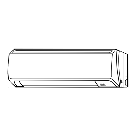
Page 4: Part Names And Functions
PART NAMES AND FUNCTIONS MSZ-A09NA MSY-A15NA MSZ-A24NA MSY-A24NA MSZ-A12NA MSY-A17NA MSZ-GA24NA MSY-GA24NA MSZ-A15NA MSZ-A17NA Front panel Air inlet Heat exchanger Panel Air cleaning filter (Anti-Allergy Enzyme Filter, Blue bellows type) Catechin air filter Air outlet Vertical vane Remote controller Horizontal vane... -
Page 5: Specification
SPECIFICATION Indoor unit model MSZ-A09NA MSZ-A12NA External fi nish White Power supply V, phase, Hz 208/230, 1, 60 Max.-fuse size (time delay) / Disconnect switch Min. circuit ampacity Fan motor F.L.A 0.76 152-229-307-338 152-240-353-388 COOL Dry (Wet) Airfl ow (134-205-275-303) (134-215-318-349) Low–Med.–High–Powerful... - Page 6 Air fl ow (CFM) (ft./sec.) range (ft.) HEAT 16.8 23.4 ● The air coverage range is the fi g- MSZ-A09NA 16.8 23.4 ure up to the position where the COOL 15.1 21.0 air speed is 1 ft./sec., when air is...
-
Page 7: Outlines And Dimensions
OUTLINES AND DIMENSIONS MSZ-A09NA MSY-A15NA MSZ-A12NA MSY-A17NA MSZ-A15NA MSZ-A17NA Unit: inch Conduit plate(MSZ-A•NA- and MSY-A•NA- are excluded.) 30-11/16 7/16x1 Oblong hole 7/16x13/16 Oblong hole Installation plate 2-3/16 8-7/8 8-7/8 2-3/16 hole 6-1/8 6-1/8 1-3/4 2-3/16 2-3/4 13-3/16 12-5/8 Indoor unit... -
Page 8: Wiring Diagram
WIRING DIAGRAM MSZ-A09NA MSY-A15NA MSZ-A12NA MSY-A17NA MSZ-A15NA MSZ-A17NA MSZ-A24NA MSY-A24NA MSZ-GA24NA MSY-GA24NA... -
Page 9: Refrigerant System Diagram
REFRIGERANT SYSTEM DIAGRAM MSZ-A09NA MSZ-A15NA MSY-A15NA Unit: inch MSZ-A12NA MSZ-A17NA MSY-A17NA Refrigerant pipe ø1/2 Refrigerant pipe ø3/8 (with heat insulator) (with heat insulator) Indoor coil Indoor coil Indoor Indoor thermistor thermistor heat RT12(main) heat RT12(main) exchanger exchanger Distributor Flared connection... -
Page 10: Service Functions
SERVICE FUNCTIONS MSZ-A09NA MSZ-A12NA MSZ-A15NA MSZ-A17NA MSZ-A24NA MSY-A15NA MSY-A17NA MSY-A24NA MSZ-GA24NA MSY-GA24NA 7-1. TIMER SHORT MODE For service, set time can be shortened by short circuit of JPG and JPS on the indoor electronic control P.C. board. The time will be shortened as follows. (Refer to 8-7.) Set time: 1-minute →... -
Page 11: Troubleshooting
Therefore, the special counter-measures are required to prevent the main voltage-drop or the rush of the starting current by adding to the system that allows the units to start one by one. TROUBLESHOOTING MSZ-A09NA MSZ-A12NA MSZ-A15NA MSZ-A17NA MSZ-A24NA MSY-A15NA MSY-A17NA MSY-A24NA MSZ-GA24NA MSY-GA24NA 8-1. CAUTIONS ON TROUBLESHOOTING 1. - Page 12 3. Troubleshooting procedure 1) First, check if the OPERATION INDICATOR lamp on the indoor unit is flashing ON and OFF to indicate an abnormality. To make sure, check how many times the abnormality indication is flashing ON and OFF before starting service work. 2) Before servicing check that the connector and terminal are connected properly.
-
Page 13: Failure Mode Recall Function
8-2. FAILURE MODE RECALL FUNCTION Outline of the function This air conditioner can memorize the abnormal condition which has occurred once. Even though LED indication listed on the troubleshooting check table (8-4.) disappears, the memorized failure details can be recalled. 1. - Page 14 2. Indoor unit failure mode table Left lamp of OPERATION Abnormal point Condition Correspondence INDICATOR lamp (Failure mode) Not lighted Normal — — The room temperature thermistor short or 1-time fl ash every Room temperature Refer to the characteristics of the room temperature open circuit is detected every 8 seconds dur- 0.5-second thermistor...
- Page 15 8-3. INSTRUCTION OF TROUBLESHOOTING Start Indoor unit operates. Indoor unit does Indoor unit oper- OPERATION INDICATOR Outdoor unit does ates. not receive the lamp on the indoor unit is not operate normally. signal from re- Outdoor unit fl ashing ON and OFF. mote controller.
-
Page 16: Troubleshooting Check Table
8-4. TROUBLESHOOTING CHECK TABLE Before taking measures, make sure that the symptom reappears for accurate troubleshooting. When the indoor unit has started operation and detected an abnormality of the following condition (the first detection after the power ON), the indoor fan motor turns OFF and OPERATION INDICATOR lamp flashes. OPERATION INDICATOR Lighted Blinking... - Page 17 fi rst has manual. setting not operate. the priority. 8-5. TROUBLE CRITERION OF MAIN PARTS MSZ-A09NA MSZ-A12NA MSZ-A15NA MSZ-A17NA MSZ-A24NA MSY-A15NA MSY-A17NA MSY-A24NA MSZ-GA24NA MSY-GA24NA Part name Check method and criterion Figure Room temperature Measure the resistance with a tester.
-
Page 18: Troubleshooting Flow
8-6. TROUBLESHOOTING FLOW A Check of indoor fan motor The indoor fan motor error has occurred, and the indoor fan does not operate. Turn OFF the power supply. Pay careful attention to the high voltage on the fan motor connector CN211. Turn ON the power supply, wait 5 seconds or more, and then press EMERGENCY OPERATION switch. - Page 19 B Check of remote controller and indoor electronic control P.C. board Check if the remote controller is exclusive for this air conditioner. Press OPERATE/STOP (ON/OFF) button on the remote controller. Is LCD display on the remote controller Replace the batteries. (Refer to 8-1.4.) visible? (Not clear) Remove the batteries, then set them back...
- Page 20 C Check of indoor electronic control P.C. board and indoor fan motor Turn OFF the power supply. Remove indoor fan motor connector CN211 and vane motor connector CN151 from the indoor electronic control P.C. board and turn ON the power supply. Measure the resistance between Short/open circuit: CN211...
- Page 21 D How to check miswiring and serial signal error Turn OFF the power supply. Is there rated voltage in the Check the power supply. power supply? Turn ON the power supply. Is there rated voltage between outdoor terminal block S1 and Check the wiring.
- Page 22 E Electromagnetic noise enters into TV sets or radios Is the unit grounded? Ground the unit. Is the distance between the antennas Extend the distance between the antennas and and the indoor unit within 9.91 ft., or is the indoor unit, and/or the antennas and the the distance between the antennas and outdoor unit.
- Page 23 8-7. Test point diagram and voltage MSZ-A09NA MSZ-A12NA MSZ-A15NA MSZ-A17NA MSY-A15NA MSY-A17NA Indoor electronic control P.C. board Power supply input Varistor (NR11) 208/230 VAC Fuse (F11) 250 V 3.15 A Resistor (R111) Indoor fan motor (CN211) 294/325 VDC (-) Fiducial terminal of...
- Page 24 MSZ-A24NA MSY-A24NA MSZ-GA24NA MSY-GA24NA Indoor electronic control P.C. board Resistor Release of Auto restart Power supply input (R111) function Varistor (NR11) 208/230 VAC Fuse (F11) Solder the Jumper wire 250 V 3.15 A to JR07 (Refer to 7-3.) Indoor fan motor (CN211) 294/325 VDC (-) Fiducial terminal of...
-
Page 25: Disassembly Instructions
Locking lever lever. Connector 9-1. MSZ-A09NA MSZ-A12NA MSZ-A15NA MSZ-A17NA MSY-A15NA MSY-A17NA OPERATING PROCEDURE PHOTOS 1. Removing the panel Photo 1 (1) Remove the horizontal vane. (2) Remove the screw caps of the panel. Remove the screws. - Page 26 OPERATING PROCEDURE PHOTOS 2. Removing the electronic control P.C. board, the Photo 4 power monitor receiver P.C. board, SW P.C. board and the terminal block (1) Remove the horizontal vane, the panel (refer to 1.) and the corner box. (2) Remove the screw of the conduit cover, and conduit cover. (Photo 2 or Photo 3) (3) Remove the indoor/outdoor connecting wire.
- Page 27 OPERATING PROCEDURE PHOTOS 4. Removing the horizontal vane motor unit Photo 7 (1) Remove the horizontal vane, the panel (refer to 1.) and the corner box. (2) Remove the screws of the horizontal vane motor unit, and Screws of the pull out the horizontal vane motor unit.
- Page 28 9-2. MSZ-A24NA MSY-A24NA MSZ-GA24NA MSY-GA24NA OPERATING PROCEDURE PHOTOS 1. Removing the front panel Photo 1 Front panel (1) Remove the screw caps of the front panel. Remove the screws. (2) Pull the panel down to your side slightly and unhook the catches at the top.
- Page 29 OPERATING PROCEDURE PHOTOS 4. Removing the vane motor Photo 4 (1) Remove the front panel. (Refer to 1.) (2) Remove the electrical cover. (Refer to 2.) Vane motors Screws (3) Remove the lead wire of vane motor. (Refer to 3.) of the (4) Remove the R.L.
-
Page 30: Parts List
PARTS LIST 10-1. PARTS LIST (non-RoHS compliant) MSZ-A09NA MSZ-A12NA MSY-A15NA MSY-A17NA MSZ-A15NA MSZ-A17NA 1. INDOOR UNIT STRUCTURAL PARTS 2. ACCESSORY AND REMOTE CONTROLLER (See 10-1.5.) 1. INDOOR UNIT STRUCTURAL PARTS Q'ty/unit Symbol Part No. Part name in Wiring MSZ- MSY-... - Page 31 MSZ-A09NA MSZ-A12NA MSZ-A15NA MSZ-A17NA MSY-A15NA MSY-A17NA 3. INDOOR UNIT ELECTRICAL PARTS AND FUNCTIONAL PARTS Q'ty/unit Symbol Part No. Part name in Wiring MSZ- MSY- Remarks Diagram A09NA A12NA A15NA A17NA A15NA A17NA 1 E02 751 509 BEARING MOUNT 2 E02 001 504...
- Page 32 MSZ-A09NA MSZ-A12NA MSZ-A15NA MSZ-A17NA MSY-A15NA MSY-A17NA 4. INDOOR UNIT HEAT EXCHANGER Q'ty/unit Symbol Part No. Part name in Wiring MSZ- MSY- Remarks Diagram A09NA A12NA A15NA A17NA A15NA A17NA E02 A54 620 INDOOR HEAT EXCHANGER E02 A56 620 E02 815 666 ø3/8...
- Page 33 MSZ-A24NA MSY-A24NA 6. INDOOR UNIT STRUCTURAL PARTS 7. INDOOR UNIT HEAT EXCHANGER (See 10-1.10.) 6. INDOOR UNIT STRUCTURAL PARTS Part number that is circled is not shown in the illustration. Symbol Q'ty/unit Part No. Part Name in Wiring Remarks MSZ-A24NA MSY-A24NA Diagram 1 E02 527 970...
-
Page 34: Remote Controller
MSZ-A24NA MSY-A24NA 9. ACCESSORY AND 8. INDOOR UNIT FUNCTIONAL PARTS AND REMOTE CONTROLLER ELECTRICAL PARTS 8. INDOOR UNIT FUNCTIONAL PARTS AND ELECTRICAL PARTS Part numbers that is circled is not shown in the illustration. Symbol Q'ty/unit Part No. Part Name in Wiring Remarks MSZ-A24NA... - Page 35 10. AIR CLEANING FILTER (ANTI-ALLERGY ENZYME FILTER) ● AIR CLEANING FILTER removes fine dust of 0.01 micron from air by means of static electricity. ● Normal life of AIR CLEANING FILTER is 1 year. If AIR CLEANING FILTER is to be washed, soak AIR CLEANING FILTER in water (when showing dirt, in lukewarm water) and rinse it delicately, without removing the filter from the frame about once every 3 months.
-
Page 36: Rohs Parts List
10-2. RoHS PARTS LIST (RoHS compliant) MSZ-A09NA MSZ-A12NA MSY-A15NA MSY-A17NA MSZ-A15NA MSZ-A17NA 2. ACCESSORY AND REMOTE 1. INDOOR UNIT STRUCTURAL PARTS CONTROLLER (See 10-2.5.) 1. INDOOR UNIT STRUCTURAL PARTS Q'ty/unit Symbol MSZ-A MSY-A Part No. Part name in Wiring Remarks... - Page 37 MSZ-A09NA MSZ-A12NA MSZ-A15NA MSZ-A17NA MSY-A15NA MSY-A17NA 3. INDOOR UNIT ELECTRICAL PARTS AND FUNCTIONAL PARTS Q'ty/unit Symbol MSZ-A MSY-A Part No. Part name in Wiring Remarks 09NA 12NA 15NA 17NA 15NA 17NA Diagram 1 G E12 751 509 BEARING MOUNT 2 G E12 001 504...
- Page 38 MSZ-A09NA MSZ-A12NA MSZ-A15NA MSZ-A17NA MSY-A15NA MSY-A17NA 4. INDOOR UNIT HEAT EXCHANGER Q'ty/unit Symbol MSZ-A MSY-A Part No. Part name in Wiring Remarks 09NA 12NA 15NA 17NA 15NA 17NA Diagram G E12 A54 620 INDOOR HEAT EXCHANGER G E12 A56 620 G E12 815 666 ø3/8...
- Page 39 MSZ-A24NA MSY-A24NA MSZ-GA24NA MSY-GA24NA 6. INDOOR UNIT STRUCTURAL PARTS 7. INDOOR UNIT HEAT EXCHANGER (See 10-2.10.) 6. INDOOR UNIT STRUCTURAL PARTS Part number that is circled is not shown in the illustration. Q'ty/unit Symbol MSZ- MSY- Part No. Part Name in Wiring Remarks A24NA...
- Page 40 MSZ-A24NA MSY-A24NA MSZ-GA24NA MSY-GA24NA 8. INDOOR UNIT FUNCTIONAL PARTS AND ELECTRICAL PARTS Part numbers that are circled are not shown in the illustration. Q'ty/unit Symbol MSZ- MSY- Part No. Part Name in Wiring Remarks A24NA A24NA GA24 GA24 Diagram G E12 527 302 LINE FLOW FAN G E12 408 509 BEARING MOUNT...
- Page 41 MSZ-A24NA MSY-A24NA MSZ-GA24NA MSY-GA24NA 9. ACCESSORY AND REMOTE CONTROLLER Q'ty/unit Symbol MSZ- MSY- Part No. Part Name in Wiring Remarks A24NA A24NA GA24 GA24 Diagram G E12 A58 426 KM06B G E12 A53 426 KM06D REMOTE CONTROLLER G E12 C26 426 KM07K G E12 C29 426 KM07M...
-
Page 42: Microprocessor Control
MICROPROCESSOR CONTROL MSZ-A09NA MSZ-A12NA MSZ-A15NA MSZ-A17NA MSZ-A24NA MSY-A15NA MSY-A17NA MSY-A24NA MSZ-GA24NA MSY-GA24NA WIRELESS REMOTE CONTROLLER These pictures show MSZ-A24. Signal transmitting section (This diagram shows an overall view.) Operation display section ON/OFF (operate/ stop) button VANE button (Horizontal vane button) - Page 43 11-1. COOL ( ) OPERATION (1) Press OPERATE/STOP (ON/OFF) button. OPERATION INDICATOR lamp of the indoor unit turns on with a beep tone. (2) Select COOL mode with OPERATION SELECT button. (3) Press TEMPERATURE buttons (TOO WARM or TOO COOL button) to select the desired temperature. The setting range is 61 ~ 88°F.
- Page 44 (4) The initial set temperature is decided by the initial room temperature. Initial room temperature Model Initial set temperature 79°F or more 75°F COOL mode of "I FEEL CONTROL" 77 to 79°F Initial room temperature minus 4°F Less than 77°F DRY mode of "I FEEL CONTROL"...
- Page 45 11-7. AUTO VANE OPERATION 1. Horizontal vane (1) Vane motor drive These models are equipped with a stepping motor for the horizontal vane. The rotating direction, speed, and angle of the motor are controlled by pulse signals (approx. 12 V) transmitted from indoor microprocessor. (2) The horizontal vane angle and mode change as follows by pressing VANE CONTROL button.
- Page 46 (9) To change the airfl ow direction not to blow directly onto your body. (MSZ-A09/12/15/17, MSY-A15/17) HEAT To change the airfl ow When to use this function? COOL/DRY direction (For MSZ) Pressing and holding Use this function if you do The air conditioner starts the The air conditioner starts heating VANE CONTROL button...
- Page 47 (5) WIDE MODE ( By selecting WIDE mode with WIDE VANE button, indoor fan speed becomes faster than setting fan speed on the remote controller ( ). The remote controller displays “ ”. NOTE: The position of vane angle 3, angle 4 and angle 5 are different in COOL operation and HEAT operation. Indoor fan speed becomes faster than setting fan speed on the remote controller even when selected.
- Page 48 Press RESET button gently using a thin stick. HEAD OFFICE: TOKYO BLDG., 2-7-3, MARUNOUCHI, CHIYODA-KU, TOKYO 100-8310, JAPAN © Copyright 2006 MITSUBISHI ELECTRIC CO.,LTD Distributed in Mar. 2009. No. OB450 REVISED EDITION-D 4 Distributed in Jun. 2008. No. OB450 REVISED EDITION-C 6 Distributed in May 2007.