
Related Manuals for Nortrac NorTrac 40XT


Summary of Contents for Nortrac NorTrac 40XT
- Page 1 NorTrac 40XT and 50XT Tractors Owner’s Manual Sold By Northern Tool & Equipment, Inc. P.O. Box 1299 Burnsville, MN 55337 Tel.: 1-800-222-5381 www.northerntool.com YFXT40-50OMAN...
- Page 2 User Notices NorTrac 40XT and 50XT Tractors Product Identification Data Sheet Product Part Number Product Model Machine Serial Number Chassis Serial Number Engine Model Engine Serial Number Date of Purchase Where Purchased/Contact Information Owner Name Complete this form carefully at purchase.
- Page 3 User Notices Thank You Thank you for purchasing a NorTrac tractor from Northern Tool & Equipment Company. We value you as a customer and wish you many years of safe and satisfied use of your tractor. Using Your Owner’s Manual This Owner’s Manual is an important part of your tractor and should remain with the tractor if you sell it.
- Page 4 This manual describes safety precautions as well as running-in, proper usage, technical maintenance, adjustment, faults and troubleshooting methods for various parts of the NorTrac 40XT and 50 XT tractors. The manual gives an in-depth look and should be used as a reference tool for owners and maintenance personnel.
-
Page 5: Table Of Contents
Table of Contents Table of Contents 1. Safety Precautions ........................... 1 1.1 Safety rules and notices of use ......................... 1 1.2 Safety warning symbols ........................... 5 1.3 Preventing farm machine hazards ......................9 2. Operating Instructions .......................... 13 2.1 Commonly used identifiers ........................13 2.2 Product description .......................... - Page 6 Table of Contents 4.9 Air cleaner instructions and maintenance ....................70 4.10 Fan belt tension adjustment ......................... 71 4.11 Engine oil level check, oil and oil filter replacement................71 4.12 Fuel injection pump maintenance ......................71 4.13 Engine oil filter maintenance ....................... 71 4.14 Lifter hydraulic oil filter maintenance ....................
-
Page 7: Safety Precautions
Safety Precautions 1. Safety Precautions 1.1 Safety Rules and Notices of Use Reading Prior to Use The instructions for use, maintenance, and the safety warning identifiers should be fully read and understood. The correct usage and operating method should be observed. Local traffic rules and safety regulations must be observed at all times. - Page 8 Safety Precautions Waste Oil Disposal 1. Used machine oil is a hazardous waste. Dispose of it properly. 2. The used acid from the battery is also a hazardous waste. Dispose of it properly. Waste oil disposal Fig.1-5 Hydraulic Line Leaks Do not use your hand to check for leaks in the high-pressure hydraulic oil lines.
- Page 9 Emergency Procedures 1. In case of a brake failure, hold the steering wheel firmly, wait until the tractor has come to a complete stop and then shut down the engine. 2. If the steering malfunctions, brake immediately and shut down the engine. 3.
- Page 10 20. Always operate the tractor at a safe speed. 21. When attaching implements, make sure all 3-Point hitch pins are securely fastened. When disconnecting implements assure all 3-Point hitch pins are disconnected. 22. When lifting, reduce engine speed to avoid damage to tractor and personal injury. 23.
-
Page 11: Safety Warning Symbols
4. Hanging farm implements can shift tractor weight. They should be low to the ground before exiting the tractor. 5. Antifreeze should always be used in the engine cooling system. 6. The front driving axle of tractor should only be engaged in agricultural instances and when roads are muddy. - Page 12 Never sit on the fender when the tractor is operating as this could result in falling from the vehicle and possible injury. Location: front side of the mudguard. Fig. 1-12 Safety warning identifier To avoid injury, stay a safe distance from the lifting lever when the lifting lever control system is in operation.
- Page 13 Always start the engine from a secure position in the driver’s seat. Location: in front of the instrument panel. Fig. 1-16 Safety startup symbol Read and understand all instruction for use, including the meaning of all non-lettered safety symbols. Location: in front of the instrument panel. Fig.
- Page 14 For battery service, carefully read the instructions in order to understand the correct maintenance procedures. Location: on the surface of the battery. Fig. 1-20 Battery symbol To prevent the risk of fire, never refuel the tractor while it is running. Guard against Fire:Guard against fire:Guard Guard against fire: 1.
-
Page 15: Preventing Farm Machine Hazards
1.3 Preventing Farm Machine Hazards The following article describes important general safety precautions for machinery such as the NT-204C/NT-254 tractor. It is reprinted here with permission from Professor Thomas L. Bean, Safety Leader and Professor, Department of Food, Agricultural, and Biological Engineering, The Ohio State University Extension, The Ohio State University. - Page 16 rapidly that they may not be visible, so it is easy to forget they are operating or to underestimate the hazard. Because some shear and cutting points cannot be guarded, it is important to be aware of their hazard and stay alert when they are operating.
- Page 17 Replace any damaged manufacturer-installed warning labels and place warnings on equipment parts not previously labeled. In addition, consider painting them a bright color, perhaps with wide stripes. Be aware of wrap points and be alert to their danger. Crush Points Crush points are created when two objects move toward each other or one object moves toward a stationary object.
- Page 18 Springs Compressed springs (Fig. 4 below) will expand with great force when released, and springs that are stretched will contract rapidly when released. Know what direction a spring will move and how it might affect another machine part when released, and stay out of its path. Figure 4 Burn Points Be aware of burn points: mufflers, manifolds and even gear cases under adverse climatic conditions.
-
Page 19: Operating Instructions
Operation Description 2. Operating Instructions NOTE : Operating the tractor properly will result in maximum performance efficiency, reducing tractor wear and helping to prevent accidents. 2.1 Commonly Used Identifiers Table 2-1 Common Symbols Symbols Definition Symbols Definition Symbols Definition Safety warning Four-wheel Horn identifier... -
Page 20: Product Description
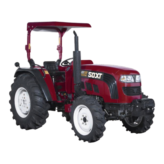
Operation Description 2.2 Product Description The following information will help you use, maintain, adjust and troubleshoot the 40XT and 50XT tractors. These series of wheeled tractor are medium-sized tractors that can be used in a variety of land types. The tractors have a compact structure and are easy to control with responsive steering, a high lift capacity and low maintenance. - Page 21 Operation Description 2.3.1 Tractor Instrumentation Instruments and Gauges This tractor uses combined instruments and controls. The instrument combination includes the following: a water temperature gauge, a fuel level gauge, an engine tachometer, a turn signal indicator, a high/low headlight indicator, a battery charging indicator, and an oil pressure alarm. 1.
- Page 22 Operation Description Fuel Gauge The fuel gauge shows how much fuel is in the fuel tank. If the gauge is in the red area, this means that the fuel level is low and the tank should be refilled immediately. Figure 2-5 Fuel Gauge Charging Indicator (Red) When the power is on but the engine is not running, the light is lit.
- Page 23 Operation Description Headlight Indicator(Green) The headlights should be used when operating the tractor on the road at night, and to ensure safety when parking the vehicle. When the headlights are operating properly, the headlight indicator lamp will light up green. When the headlight indicator lamp is green, the position lights around the tractor should be illuminated.
- Page 24 Operation Description 2.3.2 Tractor Control Switches Headlight and Taillight Switch Position ―2‖ Instrument panel lights are on, taillights are on, headlights are on if high/low dimmer switch is set to high or low beam. Position ―1‖: Instrument panel lights are on, headlights and taillights are off. Position ―0‖: Headlights, taillights, and instrument panel lights are off.
-
Page 25: Starting The Engine
Operation Description Ignition Switch Put the key into the ignition switch and turn it clockwise to the following positions: Turn the key to ACC to start the auxiliary electrical components, such as the heater, the wipers, fan, etc. Turn the key to the ON to power on the ignition and the Figure 2-18 Ignition Switch electrical system. - Page 26 Operation Description that the diesel engine starts smoothly. The procedure is as follows: (1) Loosen the bleed screw on the fuel filter. (2) Bleed the air in the fuel line from fuel tank to the diesel fuel filter with a hand pump until there are no bubbles in the discharged fuel (3) Tighten the bleed screw on the filter and loosen the bleed screw on the fuel pump to bleed out air until there are no air bubbles in the fuel (4) Remove the hand pump and tighten the bleed screw on the fuel pump.
-
Page 27: Running The Engine
Operation Description Starting the Engine in Low Temperatures (below 40 When starting the tractor in low temperatures (below 40 F), use the engine preheater. Put the fuel throttle lever in the one-quarter throttle position, turn the key clockwise to H position and leave it on H for 15–20 seconds. -
Page 28: Putting The Tractor In Motion
Operation Description 2.6 Putting the Tractor in Motion IMPORTANT ISSUES To prevent tooth breakage of the gears in the transmission or early clutch damage, do not start the engine in the High gear range. Release the parking brake before starting to avoid damage to operating parts. When putting the tractor into gear or shifting gears, the clutch pedal should be depressed to disengage the clutch and prevent gear teeth in the transmission from being broken or the clutch from being damaged. - Page 29 Operation Description IMPORTANT ISSUES: When turning the front wheel sharply, to prevent damage to the hydraulic steering system, the steering wheel may pull back slightly. This is to prevent the hydraulic steering system from being overloaded. Before making turns or backing up during field work, make sure that any towed machinery is lifted from the soil to avoid damage.
-
Page 30: Shifting Gears
Operation Description 2.8 Shifting Gears The tractor uses the main gearshift lever (A), the high/low gear shift lever (B) and the forward/reverse shuttle gear lever (C) to manage gear shifting. The tractor has four gear settings and two gear ranges, L for low speed and H for high speed. - Page 31 Operation Description Select the speed of the tractor based on the type of work being done in order to prolong the life of the engine and various parts. Only by doing so will you be able to get the best performance out of the tractor and the most longevity.
-
Page 32: Differential Lock
2.10 Front Drive Axle Use The NorTrac 40XT and 50XT series of 4-wheel drive tractors can be used for normal operations in the field and on wet and soft soil. If only rear wheel drive is used, the traction may be insufficient. When this happens, connecting the front drive axle will increase the traction of the tractor and reduce the slippage. -
Page 33: Tractor Braking
Operation Description NOTE: When driving on a hard road, the front wheel tires will wear rapidly and the left and right sides of tire tread patterns will be worn unevenly. For this reason, it is a good practice to switch the left and right tires on occasion. -
Page 34: Tire Assembly And Disassembly
Operation Description WARNING: 1. Never leave the tractor unattended with the engine running. Leaving the tractor running could result in the tractor accidentally moving and going out of control, which can result in a serious accident. 2. If the tractor has to be parked on a slope, engage the gears. Set the shuttle gearshift to forward on an uphill slope and reverse on a downhill. -
Page 35: Counterweights
Operation Description IMPORTANT ISSUES: The inflation pressure for the front and rear tires on a 4-wheel drive tractor should be the same in order to prevent the tires from being worn unevenly. 2.13.2 Tire Removal and Refit Tire Removal Special tools are needed to assemble and disassemble a tire. Contact a qualified tire service center to replace tires. -
Page 36: Hydraulic Suspension System, Pto And Electrical System Operation
Operation Description NOTE: For safety, the seat should not be adjusted while the tractor is in motion. Never adjust the rigidity of seat so that it is too soft. This can cause problems when running the tractor on uneven surfaces resulting in a possible accident. 2.16 Hydraulic Suspension, PTO, and Electrical System Operation The Series 40XT and 50XT tractors use a semi-separate hydraulic lifting system with two types ofadjustment... - Page 37 Operation Description 2.16.3 Application of the Hydraulic Output and Lock Turn the adjustment valve (B) in a counterclockwise direction until the valve is closed. This will also close the adjustment valve on the inlet and outlet of the oil cylinder. The male connector on the quick change coupler is connected with the oil inlet of the farm implement.
- Page 38 Operation Description 2.16.4 Hydraulic Control Levers There are five levers that control the hydraulic system for farm implements towed by the tractor. Control levers (A) and (B) are hydraulic float levers. Control lever (C) controls the first hydraulic control loop (quick disconnects (A1) and (B1). ...
- Page 39 Operation Description IMPORTANT ISSUES: 1. When a quick disconnect is not used, the connector seat should be covered with a seal cover to avoid dust. 2. After the hydraulic output device is used, the operating handle should be set to the neutral position, otherwise, the hydraulic system may overheat.
- Page 40 Operation Description through the tilling width regulator. Front and rear relative position for the left and right suspension points can be changed lowering plow width regulator. The working width will then be increased when the right suspension point moves forward; otherwise the tilling width will be decreased.
- Page 41 Operation Description IMPORTANT ISSUES: 1. When a fast change coupler is not used, the seat hole should be protected with the spare dust cover. 2. The lifter and the hydraulic output valve cannot be operated at the same time. 3. After setting up the auxiliary hydraulic output connection, the operating handle should be set in the neutral position;...
- Page 42 Operation Description 2.16.8 Power Take Off (PTO) Shaft Use To connect and disconnect power to the power take off (PTO) shaft the double-acting clutch, the PTO gear shift handle, and the PTO disconnect control handle are used. When the clutch pedal is pushed down part way it disconnects the engine clutch, and when it is pushed down all the way down it disconnects the PTO clutch.
- Page 43 Operation Description 2.16.9 Electrical Equipment Use The electrical systems of the 40XT and 50XT Series Tractors use a 12V double wire system with a negative ground. 2.16.9.1 Battery The battery is used to store the electrical energy produced by the alternator. The battery can then supply electrical power to the electrical equipment on the tractor when the alternator is not turning or is running at low speed.
- Page 44 Operation Description 2.16.9.4 Auxiliary Electrical Equipment The fuse box: has 15 fuses, total, 7 for normal use, and the others for spares. Fuses are used to protect electrical equipment. Replace burned out fuses immediately. Each fuse’s rating should coincide with the requirements on the electrical schematic.
- Page 45 Operation Description Fig 2-31 Electrical Schematic...
-
Page 46: Tractor Break-In
Operation Description 2.17 Tractor Break-in Before the tractor is put into service, it should run for a certain period under the specified conditions of lubrication, rotational speed and load, and at the same time have any necessary inspection, adjustments and maintenance, to normalize its technical state;... - Page 47 Operation Description throttle to lift the 3-point lift mechanism up and down for 10 minutes (minimum of 20 times). After Break in, move the distribution handle to the lower position. 2.17.5 Break-in With and Without a Load When Break in, you can have the tractor in either low or high, depending on the weight of the load. When Break in with a dead load or light load, the throttle should be open 3/4.
-
Page 48: Common Faults And Troubleshooting
Operation Description with a 50/50 water/antifreeze blend. Check the front wheel toe-in and free play of clutch and brake pedal. Adjust if necessary. Check and tighten the bolts nuts, and screws that are accessible. Put grease into every grease fitting. 2.18 Common Faults and Troubleshooting 2.18.1 Chassis Faults and Troubleshooting 2.18.1.1 Clutch Faults and Troubleshooting (Table 2-2) - Page 49 Operation Description Fault Causes Troubleshooting (1) The gearshift interlocking rod is too short (1) Lengthen the gearshift (2) The locating slot of the shifting fork shaft interlocking pull rod is severely worn (2) Replace the shift fork Gearshift disengages (3) The spring pressure of the interlocking (3) Adjust or replace the automatically latch is insufficient...
- Page 50 Operation Description Fault Causes Troubleshooting is too small and add if necessary (3) Readjust the gear backlash Abnormal noises from (1) The bearing, gear or shaft is damaged (1) Replace the bearing, gear the final drive or shaft (1) The free play of the brake pedal is (1) Readjust the free play of the too large brake pedal...
- Page 51 Operation Description Fault Causes Troubleshooting drive tractors) drive gear is bad meshing backlash (2) The clearance of the central drive bearing (2) Adjust or replace is too great or the bearing is damaged (3) Replace the differential axle (3) The differential axle is worn or damaged (4) Replace the planetary gear or (4) The planetary gear or gasket is worn the gasket...
- Page 52 Operation Description 2.18.1.5 Hydraulic Steering System Faults and Troubleshooting Table 2-6 Steering System and Running System Faults and Troubleshooting Fault Causes Troubleshooting (1) Steering gear thrust bearing worn (1) Replace bearings or adjust Free stroke of steering (2) Steering gear screw, nut and ball worn (2) Replace wearing parts system is too large (3) Gear sector and rack worn...
- Page 53 Operation Description Fault Causes Troubleshooting (1) The oil supply to the gear oil pump is (1) Check the gear oil pump. insufficient, or the gear oil pump leaks inside Clean the filter screen or the filter screen in the steering oil tank (2) Bleed the air from the system is blocked.
- Page 54 Operation Description 2.18.2 Hydraulic Hitch System Faults and Troubleshooting Table 2-7 Hydraulic Hitch System Faults and Troubleshooting Fault Causes Troubleshooting (1) The oil level within the 3-point lift (1) Add oil to the specified oil level is too low (2) Clean or replace the strainer on the oil filter (2) The strainer of the oil filter is blocked (3) Check for air leaks (3) Air is getting into the oil suction line...
- Page 55 Operation Description Fault Causes Troubleshooting the engine (4) The O-ring for the oil cylinder is damaged or leaking (5) The seal ring between the distributor\ or the cylinder head and the oil inlet hole on the 3-point lifter shell is improperly installed or damaged With the 3-point (1) Because of improper adjustment, the...
- Page 56 Operation Description Fault Causes Troubleshooting causes poor contact between the carbon (5) Replace starter bush and the commutator (6) Replace starter (5) Bad contact in rectifier (7) Replace starter (6) The main contacts of the solenoid switch are burned, resulting in a poor connection (7) The bearing is abraded severely, and the armature grates against the case...
- Page 57 Operation Description 2.18.3.2 Battery Faults and Troubleshooting Table 2-10 Battery Faults and Troubleshooting Fault Causes Troubleshooting (1) Short circuit between electrode plates in (1) Replace battery the battery (2) Replace battery The battery capacity is (2) Sulphurization of the electrode plates in (3) Clean battery terminal, securely low and the engine is the battery...
- Page 58 Operation Description 2.18.3.4 Headlight/Taillight/Work Light Faults and Troubleshooting Table 2-13 Headlight/Taillight/Work Lights Faults and Troubleshooting Fault Causes Solutions (1) Circuit broken, short circuit, or a (1) Check and repair, then reconnect blown fuse (2) Check and replace if necessary The headlights have no high (2) Bad contact or damage to the (3) Replace bulb beam or low beam...
-
Page 59: Accessories And Consumables
Accessories and Consumables 3. Accessories and Consumables Series 40XT and 50XT tractors have a variety of accessories and spare parts that can be used to keep your tractor in good shape and performing at its peak. Always replace existing parts that are worn or damaged with authentic, authorized parts. -
Page 60: List Of Consumables
Accessories and Consumables IMPORTANT ISSUES: 1. Optional parts should be installed under the manufacturer’s technical specifications. 2. The engine cooling system must be filled with a 50/50 water/antifreeze solution in the winter. 3.2 List of Consumables (not included with tractor purchase) Consumables for 40XT and 50XT series wheeled tractor include all bearings listed in appendix 10-4, all oil seals and seal rings listed in appendix 10-3, all fuses, bulbs, rubber boots, filters, and belts as listed in table 3-1. -
Page 61: Maintenance Instructions
Maintenance Instruction 4. Maintenance Instructions 4.1 Technical Maintenance Procedures Carrying out the technical maintenance specifications of the tractor is the effective way to prolong the service life of the tractor and reduce accidents. The technical maintenance schedule for 40XT and 50XT series tractors is based on the accumulated work hours, which includes maintenance for: every shift (per 10 work hours), every 50 work hours, every 200 work hours, every 400 work hours, every 800 work hours, every 1600 work hours, and winter and long-term storage. - Page 62 Maintenance Instruction 7. Maintain the diesel engine according to the daily-shift technical maintenance guidelines specified in the engine manual. 4.1.2 Technical Maintenance for Every 50 Work Hours 1. Perform all the requirements of the technical maintenance per shift. 2. Check the air filter and remove the dust. 3.
- Page 63 Maintenance Instruction 8. Change the oil in the engine, the transmission, the rear axle, the transfer case, the front drive axle , the hydraulic lifter, and the steering gear. 9. Check and adjust the toe-in of the front wheels. 10. Adjust the steering wheel free play. 11.
- Page 64 Maintenance Instruction 4.1.7 Specific Technical Maintenance (Winter) When the temperature is below freezing, along with the "Technical Maintenance per Shift", the following provisions should be strictly observed: 1. Select winter grade fuel and lubricating oil. 2. Check the strength of the coolant with a hygrometer. If necessary add anti-freeze to the cooling system as required to protect against coolant freezing.
- Page 65 Maintenance Instruction Table 4-1 NorTrac 40XT and 50XT Series Tractor Maintenance Maintenance Part Operation Content No. of Maintenance Interval Points Engine Oil Pan Check Oil Level Per Shift Air Filter Check Cleanliness Per Shift Battery Check Connections Per Shift Radiator...
-
Page 66: Clutch Adjustment
Maintenance Instruction 4.2 Clutch Adjustment In order to ensure the normal operation of the clutch, a clearance of (2–2.5 mm.) should be kept between the end of disengaging lever 4 of the main clutch and the surface of release bearing 5; a clearance of B = (10–11 mm.) should be kept between the end of disengaging lever 6 of the auxiliary clutch and the surface of release bearing 5. - Page 67 Maintenance Instruction 4.2.1 Dual-Action Clutch The structure of 40XT and 50XT series dual-action clutch is as shown in Figure 4-3. Clutch adjustment: With the dual-action clutch, both the main clutch and the assistant clutch can be adjusted. Main Clutch Adjustment: The distance between the main clutch release lever end face and the release bearing should be 2–2.5 mm.
- Page 68 Maintenance Instruction IMPORTANT ISSUES: 1. In order to avoid staining the friction plate with oil, the drain plug below the flywheel cover should be pulled off frequently to drain off the oil that may leak in the engine and the transmission box. If serious leakage is found, promptly identify the reasons and deal with the problems.
-
Page 69: Brake Adjustment And Maintenance
Maintenance Instruction 4.3 Brake Adjustment and Maintenance 4.3.1 When Any of the Following Occurs, the Brakes Should Be Adjusted: The free play of the brake pedal is too large, which can cause a braking failure. The free play of the brake pedal is too small, which can cause too little clearance between the brake shoe and the brake drum and cause the brakes to drag. -
Page 70: Differential Lock Adjustment
Maintenance Instruction NOTE : The free play of the left and right brake pedals of the tractor must be adjusted to be even. Otherwise, the tractor will pull to one side when emergency braking. 4.4 Differential Lock Adjustment Adjustment of differential lock is performed through adjustment of the bolts (1 and 2). During the adjustment, the clearance between the right coupling (3) and left coupling (4) is about 2 mm. -
Page 71: Front Drive Axle Adjustment
Maintenance Instruction 4.6 Front Drive Axle Adjustment 4.6.1 Front Axial Clearance and Toe-In (see Figure 4-5) The front axle of the tractor uses an adjustable tubular front axle, which is located in the front of the diesel engine. The carrier and the diesel are fixed by 6 screws; the pendulum shaft is supported by both ends of the carrier and is sheathed with a sleeve welding assembly. - Page 72 Maintenance Instruction 4.6.2 Front Axle Adjustment (2 Wheel Drive Model) Front-Wheel Bearing Axial Clearance Adjustment (Figure 4-6) : The normal axial clearance of front-wheel bearing should be 0.05–0.15 mm. During operation, it should be adjusted if the clearance increases to 0.4 mm. When adjusting, jack up the front wheel, remove the bearing cap, pull out the cotter pin and turn the castle nut until the bearing clearance is eliminated.
- Page 73 Maintenance Instruction 4.6.4 Front Drive Axle Structure and Adjustment (Figure 4-7) (4 Wheel Drive Model) The power of front drive is transmitted to the front central drive via the transfer case. The power is distributed into the half-axle on two sides by the front central drive, then transmitted to the final drive to make the driving gear turn. When working in the field where the conditions are poor, mud and water can easily get in to the front/rear lining, which will cause end face wear and the axial float to increase.
- Page 74 Maintenance Instruction connecting end of the main reducor housing. Next, measure the distance between the spacer bush and the retainer ring slot. This distance is the thickness of the adjusting gasket. Replace the adjusting gasket, and then install the retainer ring for hole.
-
Page 75: Hydraulic Lifting Mechanism Maintenance
Maintenance Instruction 4.7 Hydraulic Lifting Mechanism Maintenance Park the tractor on flat ground and bring the lifter arm to its lowest height. Shut off the engine. Remove the lifter cover dipstick and check the oil level. If the level is under the lowest mark, fill with hydraulic oil until it is between the upper and lower marks. -
Page 76: Air Cleaner Instructions And Maintenance
Maintenance Instruction 4.9 Air Cleaner Instructions and Maintenance In a dusty environment, inspect and clean the filter elements every 10 working hours. Take out the filter element and clean it with a brush, discarding the dust in the rubber filter bag. ... -
Page 77: Engine Oil Level Check, Oil And Oil Filter Replacement
Maintenance Instruction 4.13 Engine Oil Filter Maintenance It is recommended that the oil filter be changed every time the oils is changed, especially when working in dusty conditions. 4.14 Lifter Hydraulic Oil Filter Maintenance The lifter oil filter is located on the lower right hand side of the engine. Perform maintenance according to specifications. -
Page 78: Fuel Tank Maintenance
Maintenance Instruction 4.20 Engine Cooling System Maintenance Use a 50/50 water/antifreeze mix in the cooling system all year long. Engine coolant should be replaced every two years or as needed depending on work hours. To change the engine coolant, first allow the engine to cool down. Open the valve at the bottom of the radiator and drain the radiator coolant into a suitable container. -
Page 79: Bleeding The Fuel System
Maintenance Instruction 3. Check the thermostat performance regularly. This can effect the coolant circulation and cause the tractor to run hot. 4.22 Bleeding the Fuel System If the tractor is parked for a long period of time or you are replacing the diesel fuel filter element or you have an empty fuel tank, air could get into the fuel line, which could cause starting problems. -
Page 80: Rear Axle Structure And Adjustment
Maintenance Instruction NOTE: The right and left pedal free path should be the same as the brake pedal free path. Otherwise, in an emergency braking situation, the tractor may pull to one side. For safety sake, do a braking test after making the adjustments. Interlock the right and left brake pedals. On a dry, flat road, hit the brakes while running at high speed in a straight line. - Page 81 Maintenance Instruction The rear axle center drive is composed of a pair of spiral bevel gears. The back end of bevel pinion shaft is supported by a conical roller bearing and the front end is supported by an internal cylindrical roller bearing.
-
Page 82: Storage
Storage 5. Storage When the tractor is going to be out of use for an extended period of time (more than one month) it should be kept in a proper storage building. The storage facility should provide protection from the elements so as to keep the tractor clean and prevent rust and corrosion. -
Page 83: Tractor Storage Maintenance
Storage Loosen the fan belt on the engine and remove it if necessary. Wrap the belt(s) securely and spray the pulley groove with a rust-proof agent. If possible, paint over all chips in the paint and cover non-painted metal parts with a preservative. ... -
Page 84: Removing Tractor From Storage
Storage 5.4 Removing Tractor from Storage Remove the grease used for anti-rusting. Reopen the various sealed up nozzles and clean the tractor. Check coolant, machine oil, and diesel fuel and lubricate all of the lubrication points acco rding to the provisions. -
Page 85: Transportation
Transportation 6. Transportation If the tractor is to be driven by the owner, local traffic regulations should be strictly observed with at least 180 feet of distance maintained between vehicles. If the tractor is being transported , the following procedures should be followed: A smooth, level spot should be selected for loading and unloading the tractor. -
Page 86: Technical Specifications
Technical Specifications 7. Technical Specifications 7.1 Table of Product Technical Specifications Table 7-1 Table of Product Technical Specifications NorTrac Item Unit 40XT 50XT 4×4 4×4 — Type Wheeled Wheeled Nominal Traction Power 10.5 Max Power of the PTO Shaft 27.9 35.0 Length (incl. - Page 87 Technical Specifications NorTrac Item Unit 40XT 50XT Front Counterweight Counter- weight Rear Counterweight — Type Xinchang A498BT Xinchang A498BT — Type Vertical lined, four-stroke, direct-spray, water-cooling — Number of Cylinders Cylinder Diameter x 98×105 98×105 Stroke Nominal Power 29.4 36.8 Nominal Rotate 2200/2400 2400...
- Page 88 Technical Specifications NorTrac Item Unit 40XT 50XT Central transmission shaft Transmission — Shaft Central — Transmission, Bevel gear, close Front Front — 2 planet bevel gears Differential Final — Transmission, Spiral bevel gear Front — Frame Assembly Frameless — Front Suspension Rigid suspension —...
- Page 89 Technical Specifications NorTrac Item Unit 40XT 50XT — Hydraulic Oil Pump CB-F312 — Distributor Built-in unloading control Diameter x 90×110 95×120 cyl- Stroke — inder Type Single-action Rear, three points suspension: Cat.I Rear, three points suspension: Cat.II Size of Upper suspension point: Joint hole x width: φ19.3×44 Upper suspension point: Joint hole x width: φ25.2×51 Suspension Point Bottom suspension point: Joint hole x width: φ22.4×35...
- Page 90 Technical Specifications NorTrac Item Unit 40XT 50XT Electric — 12 volts, negative earth, twin-wire Appliance System — — Alternators JF15(XinchangA498、C490) Voltage Power 350(JF131, JF131AX, JF11A) 500(JF151, JFW15, JF15A, JF15) — Type Included in the electric appliance box FT300.48D.2.2 Regulated Voltage —...
- Page 91 Technical Specifications NorTrac Item Unit 40XT 50XT Comb- — ination Rev. meter, water temp. meter, oil pressure gauge, fuel meter, one piece Watch Instruments 1. Charge indicator, L/R turn signal indicator, parking light, low beam indicator Warning Warning 2. Low oil pressure alarm light —...
-
Page 92: Disassembly And Disposal
Disassembly and Disposal 8. Disassembly and Disposal After the machine reaches the end of its service life, for your personal safety and the protection of the environment, please deliver it to the licensed company specialized in the disassembly and recycling of such products. -
Page 93: Warranty Terms
Warranty Terms 9. Warranty Terms LIMITED WARRANTY 4WD Diesel Tractor NorTrac equipment is sold by NorTrac; a division of Northern Tool & Equipment Company, Inc. NorTrac will repair or replace, at its option, any part(s) thereof of the NorTrac 4WD diesel tractor or compact crawler / bulldozer that are shown to be defective in material and/or workmanship, under normal use during the applicable warranty period. - Page 94 Warranty Terms Disclaimer of Consequential Damage: Any implied warranty of merchantability or fitness for a particular purpose, to the extent that either may apply to any NorTrac tractor or compact crawler / bulldozer, shall be limited in duration to the periods of the express warranties shown above, and to the extent permitted by law any and all implied warranties are excluded.
-
Page 95: Appendices
Appendicies 10. Appendicies 10.1 Tractor Fuel, Oils and Solutions (Table 10-1) Table 10-1 Tractor Fuel, Oils and Solutions Application Locations Fuel, Oils and Solutions of Oils and Solutions International Adopt ASTM D-975 fuel. Under general air temperatures, use 2-D grade fuel; Fuel Tank when ambient temperatures are below 32 F, use 1-D grade fuel standard... -
Page 96: Tightening Torque Table Of Major Bolts And Nuts
Appendicies 10.2 Tightening Torque Table of Major Bolts and Nuts (Table 10-2) Table 10-2 Tightening Torque Table of Major Bolts and Nuts Tightening Tightening Connecting Connection Specs Torque Torque Location (N·m) (ft- lbs) 77.7 57.3 Bolt connecting the engine with the gearbox Bolt connecting the gearbox with the rear axle 77.7 57.3... - Page 97 Appendicies Standard Code Name and Model Installation Position Outer end at inside of long half shaft of rear Oil Seal FB40×62×8D axle (up to 52 horsepowers) Oil Seal FB40×62×8D Intermediate section of Shaft I in the gear box Outer end at inside of long half shaft of rear Oil Seal FB40×62×8D axle (55-60 horsepowers) Driven bevel gear of second-stage reduction of...
-
Page 98: Roller Bearings
Appendicies Standard Code Name and Model Installation Position Cut-off valve and O-Rings 50×5.3G lowering valve adjusting rod Where the lowering-speed O-Rings 11.2×2.65G adjusting bar meets the housing Note: This table does not include nonstandard Oil Seals and O-Rings. 10.4 Roller Bearings (Table 10-4) Table 10-4 Rolling Bearings Standard Name and... - Page 99 Appendicies Standard Name and Installation Position Quantity Note Code Model Bearing 6203-Z Inside the flywheel of engine 30,35 use Bearing 6204-Z Inside the flywheel of engine 40 use Bearing Rear end of the rear center NUP2210 small driving bevel gear GB/T 283 Inner flank of the driven bevel gear of Bearing N208...
- Page 100 Appendicies Standard Name and Installation Position Quantity Note Code Model Steel ball Gearbox shift shaft 8.0000G100b Shfit shaft for the Steel ball 9.5V power output rear axle GB/T 308 Steering arm of front drive Steel ball 8.7312G400b Locking shaft of the lifter Steel ball Braking disc and 18.0000G100b...
- Page 101 Distributed by Northern Tool & Equipment Co., Inc. Burnsville, MN 55306-6936 Made in China...
- Page 102 40 HP On Line Spare Parts System Fill in Choose English http://222.132.52.85:8080/ Choose “Guest” Choose “Parts catalogue” Choose product Model and Code:...
- Page 103 Then search here TB40 Serials TB404-X161Y10K Then you can find the parts catalog and diagram of the tractor: TB40 Serials TB404-X161Y10K...
- Page 104 TB40 Serials TB404-X161Y10K...
- Page 105 50 HP On Line Spare Parts System Fill in Choose English http://222.132.52.85:8080/ Choose “Guest” Choose “Parts catalogue” Choose product Model and Code:...
- Page 106 Then search here TB40 Serials TB504-X161Y8K Then you can find the parts catalog and diagram of the tractor: TB40 Serials TB504-X161Y8K...
- Page 107 TB40 Serials TB504-X161Y8K...
Need help?
Do you have a question about the NorTrac 40XT and is the answer not in the manual?
Questions and answers