
Related Manuals for SILENT KNIGHT 5104B


Summary of Contents for SILENT KNIGHT 5104B
- Page 1 Model 5104B Fire Communicator Document 151053-L8 Installation and 05/05/2014 Rev: Operations Manual P/N 151053-L8-F3 ECN: 14-0068...
-
Page 2: Installation Procedure
Installation Procedure Adherence to the following will aid in problem-free installation with long-term reliability: Installation Precautions - Adherence to the following will aid in problem-free installation with long-term reliability: WARNING - Several different sources of power can be connected to the fire alarm control panel. Disconnect all sources of power before servicing. -
Page 3: Table Of Contents
Contents Section 1 Introduction .............................. 1-1 Feature .............................1-1 Accessory Devices ........................1-1 About This Manual ........................1-1 1.3.1 How to Use This Manual ....................1-2 Section 2 Agency Requirements ....................... 2-1 Telephone Requirements ......................2-1 FCC Warning ..........................2-2 UL Requirements ........................2-2 Canadian Department of Communications ................2-2 Section 3 Installation .............................. - Page 4 6.2.6.3 Go to a Step ......................6-3 6.2.7 Programming Steps ......................6-3 Section 7 Reporting ..............................7-1 Reporting Formats ........................7-1 Reporting Codes ........................7-2 Section 8 Troubleshooting ..........................8-1 Silent Knight Fire Product Warranty and Return Policy Manufacturer Warranties and Limitation of Liability 151053-L8...
-
Page 5: Introduction
151053-L8 Section 1 Introduction The Model 5104 is a low-cost fire communicator that meets the requirements for NFPA 72, UL 864, MEA, CSFM, and FM. Feature • Six supervised fire zones, consisting of one Class A (Style D) and five Class B (Style B) zones. -
Page 6: How To Use This Manual
Model 5104B Installation Manual 151053-L8 much as possible, we have tried to organize the manual chronologically by the tasks that need to be performed. Please let us know if the manual does not meet your needs in any way. 1.3.1... -
Page 7: Agency Requirements
This device may not be directly connected to coin operated telephones or party line services. This device cannot be adjusted or repaired in the field. In case of trouble with device, notify the installing company or Silent Knight for an RA number and then return it to: Silent Knight... -
Page 8: Fcc Warning
Model 5104B Installation Manual 151053-L8 FCC Warning Warning This device has been verified to comply with FCC Rules Part 15. Operation is subject to the following conditions: (1) This device may not cause radio interference, and (2) This device must accept any interference received, including interference that may cause undesired operation. -
Page 9: Installation
151053-L8 Section 3 Installation This section contains information necessary to install the 5104 Fire Communicator and accessories. Electrical Specifications Primary AC 120 Vrms @ 60Hz, 374 ma Total DC load 1.3 Amp Accessory Power 12 VDC @ 750 mA Phone Line Voltage 2.75 VDC min. -
Page 10: Wiring Specifications
Model 5104B Installation Manual 151053-L8 Wiring Specifications Induced noise (transfer of electrical energy from one wire to another) can interfere with telephone communication or even cause false alarms. To avoid induced noise, follow these guidelines: • Isolate input wiring from high current output and power wiring. Do not pull one multi-conductor cable for the entire panel. -
Page 11: Panel Description
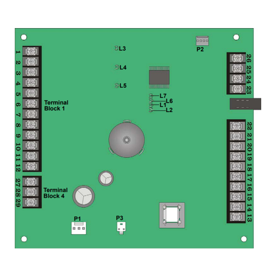
Installation 151053-L8 Panel Description This section describes the 5104 board components, including terminal strips, LEDs, Switches and cable connectors. See Figure 3-2. Terminal Block 3 Terminal Block 1 Reset/ Silence Switch Terminal Block 2 Terminal Block 4 Figure 3-2 5104 Circuit Board... -
Page 12: Terminal Description
Model 5104B Installation Manual 151053-L8 3.4.1 Terminal Description Table 3-1 lists the terminals by number and describes the terminals use. Table 3-1: Terminal Description by Terminal Block Earth Ground Terminal Electrical Terminal # Description Impedance Block # Specification (in Ohms) -
Page 13: Led Descriptions
Installation 151053-L8 3.4.2 LED Descriptions This section describes what each LED indicates. The 5104 has a total of seven LEDs, three are visible externally and four are visible only if the cabinet door is open. See Section 8 for additional information on LED operation. 3.4.2.1 Externally Visible LEDs (L3, L4, &... -
Page 14: Overcurrent Led Indicators (L1 & L2)
Model 5104B Installation Manual 151053-L8 3.4.2.3 Overcurrent LED Indicators (L1 & L2) The 5104 has two red LEDs which indicate if excessive current is being drawn by a device connected to either the Accessory Power or Smoke Power circuits. Table 3-4 lists the two overcurrent LEDs and gives a description of them. -
Page 15: Calculating Current Draw And Standby Battery
Installation 151053-L8 Calculating Current Draw and Standby Battery This section should be used to help you determine the current draw and standby battery needs for your installation. 3.5.1 Worksheet Requirements The following steps must be taken when determining the 5104 current draw and standby battery requirements. Fill in the Current Draw Worksheet (Table 3-6) in section 3.5.2. -
Page 16: Current Draw Worksheet
Model 5104B Installation Manual 151053-L8 3.5.2 Current Draw Worksheet Use this worksheet to determine current requirements during alarm/battery standby operation. Table 3-6: Current Draw Calculations Number of Standby Alarm Device Current per Device Devices Current Current For each device use this... -
Page 17: Mounting The 5104 Cabinet
A piece of plywood, standoffs, or other equivalent material can be used to space the cabinet from the concrete surface and then attach the 5104B to that spacing surface. Also mount any other desired components to the 1/4” spacing surface. -
Page 18: Ac Connection
Model 5104B Installation Manual 151053-L8 AC Connection 3.8.1 Standard Transformer Connections The AC transformer is factory mounted into the control panel and is plugged onto the control panel as shown in Figure 3-4. The ground and the primary side of the transformer should be wired as shown in Figure 3-4 by a certified electrician. -
Page 19: Detector Installation
Installation 151053-L8 3.10 Detector Installation 3.10.1 Class A (Style D) Zones Zones 1 is for a class A (style D) zone. It is intended for use with non-powered devices such as waterflow switches. Do NOT use smoke or duct detectors on Class A zones. Each class A zone is a four-wire circuit that allows an alarm to be detected even after a single open or ground fault occurs. -
Page 20: Class B (Style B) Zones
Model 7628 4.7 K EOL Figure 3-7 Model 5104B Class B (Style B) Loops Note: Does not support 2-wire detectors. Maximum Loop Resistance - 50 ohms Maximum Total alarm current for all class B (Style B) zones - 750 mA... -
Page 21: Four-Wire Smoke Detector Connection
Installation 151053-L8 3.10.3 Four-Wire Smoke Detector Connection 4-wire smoke detectors must use a power supervision module. Connect four-wire smoke detectors as shown in Figure 3-8. ESL 449CT Model 7628 EOL Resistor Model 160150 Supervision Module Figure 3-8 4-wire Smoke Detector Connections 3-13... -
Page 22: Supplemental Notification Appliance Installation
Model 5104B Installation Manual 151053-L8 3.11 Supplemental Notification Appliance Installation The Supplemental notification circuit supplies a DC output that can be used to power a DC audible device during an alarm condition. Pressing the reset / silence switch will silence the output. Refer to section 6.2.7, Step 14, to program the notification circuit’s supervision properties. -
Page 23: Supervised Notification Appliance Wiring
Installation 151053-L8 3.11.2 Supervised Notification Appliance Wiring When using a supervised notification device any open or shorted wiring condition will be reported as a trouble. Figure 3-10 illustrates how to wire a supervised notification device to the control panel. Refer to Section 6.2.7 Step 14 to program the notification circuit’s supervision properties. -
Page 24: Telephone Line Connections
Model 5104B Installation Manual 151053-L8 3.12 Telephone Line Connections The 5104 control panel connects to the phone lines with a 7860 cable, which plugs into an RJ31X phone jack. The telephone company will install an RJ31X phone jack if you request them. Both telephone lines must be installed to comply with NFPA 72. -
Page 25: Model 5230 Installation
Installation 151053-L8 3.13 Model 5230 Installation The optional 5230 remote annunciator provides both trouble and alarm annunciation, and a convenient means of English-language programming the system. Figure 3-12 Model 5230 Remote Annunciator. 3.13.1 Mounting the 5230 When installing the 5230 as a permanent component of the system it must be mounted to a dual gang electrical box. - Page 26 Model 5104B Installation Manual 151053-L8 toward you. See Figure 3-13. Restraining Tabs Wire Access Hole Restraining Mounting Holes Tabs Orientation Mark Figure 3-13 Rear Mounting Plate Set the desired ID for the 5230 by setting the dip switches (on = up) as follows:...
-
Page 27: Add-On Fire Communicator Application
151053-L8 Section 4 Add-on Fire Communicator Application The 5104 can be used to communicate the status of a larger or pre-existing (referred to as Host panel in this manual) fire control system that does not have a digital communicator. To configure the 5104 as an add-on communicator wire it as shown in Figure 4-1. -
Page 28: 5230 Operation
151053-L8 Section 5 5230 Operation This section contains information about the operation of the 5104 through a 5230 remote annunciator. 5230 Display Messages If the 5104 is not reporting, being programmed, and if no functions are being entered, the LCD will display the event of the highest priority. -
Page 29: 5230 Touchpad Functions
Model 5104B Installation Manual 151053-L8 Table 5-1: 5230 LCD Messages and Meanings Message Meaning Trouble Remote # (1-3) One or more 5230 annunciators are in trouble. The 5230 ID number is indicated in the # place. EEPROM Sum Error Error during program mode. - Page 30 5230 Operation 151053-L8 Table 5-2: Touchpad Keystrokes and Their Task or Function Task or Function Keystroke Step. SILENCE Used to advance to a different programming step while STEP followed by the desired step number. in programming mode. In reference to any Refer to Section 6 for programming information.
-
Page 31: Programming
151053-L8 Section 6 Programming This section contains information pertaining to the programming of the 5104 with the 5230 Remote Annunciator. All programming is stored in an EEPROM (Electrically Erasable Read-Only Memory) chip, which is non- volatile memory storage. The various areas of programming are referred to as programming steps. These steps are covered in greater detail in Section 6.2.5. -
Page 32: How To Exit Program Mode
Model 5104B Installation Manual 151053-L8 Press 7. Press ENTER. Enter the Installer Code. 6.2.4 How to Exit Program Mode SILENCE SILENCE CLEAR CLEAR To exit program mode press STEP STEP 6.2.5 Step Programming All programming, for the 5104, done through the 5230 is done in steps. Each step programs a set parameter of the 5104, such as phone numbers, reporting formats, and zone functions. -
Page 33: Bypass A Step
Programming 151053-L8 Special Character and Functions Some phone number require special characters or functions to dial the central station correctly. Table 6-2 lists the special character used for dialing a phone number and CIC (Carrier ID Code) codes. Table 6-2: Special Characters for Dialing Sequence Character Touchpad Inputs Displayed Character... - Page 34 Model 5104B Installation Manual 151053-L8 Table 6-3: List of Programming Steps Step # Task Choices Default Sets the 3/1 reporting format code sent for a Step 4 3/1 Test Code 0 - 9, A, B, C, D, E "Test Code". Use the Shift key plus digits 1 - 5 for letters A - E.
- Page 35 Programming 151053-L8 Table 6-3: List of Programming Steps Step # Task Choices Default Press any numeric-digit to toggle the selection from Yes to No. Yes = Bell circuit activates during alarm Step 13 Relay Alarm Yes or No condition by the auxiliary relay. No = Bell circuit activates during a dialer failed condition.
- Page 36 Model 5104B Installation Manual 151053-L8 Table 6-3: List of Programming Steps Step # Task Choices Default Set how zone 3 will report. Press any numeric- digit to toggle the selection from Yes to No. Yes = If you want to report troubles and alarms as a sprinkler (Supervisory), when using SIA format.
- Page 37 Programming 151053-L8 Table 6-3: List of Programming Steps Step # Task Choices Default Enter six-digits for an account number. For accounts shorter than 6-digits use leading zeros before you enter account number, so Step 26 Account #1 6-digits 105104 that all six places are filled. For example, if the format requires a shorter account number, such as 3/1 enter 000123.
- Page 38 Model 5104B Installation Manual 151053-L8 Table 6-3: List of Programming Steps Step # Task Choices Default Carrier Identification Code is the prefix that needs to be dialed before a phone number to access a particular long distance carrier. Use Step 37...
- Page 39 Programming 151053-L8 Table 6-3: List of Programming Steps Step # Task Choices Default Press any numeric-digit to toggle the selection from Yes to No. Yes = If the 5104 is used as an add-on communicator for a host panel. This tells the 5104 not to test the battery or earth ground, Step 49 Add-on Dialer...
-
Page 40: Reporting
151053-L8 Section 7 Reporting The 5104 can transmit information in 5 different formats. This section describes the five basic reporting formats of the 5104 and the codes that they send to a central station receiver. Of these 5 formats some of the formats offer a more specific selection for that format. -
Page 41: Reporting Codes
Model 5104B Installation Manual 151053-L8 Reporting Codes Table 7-2 list the events sent by the 5104 and the code that is sent for that event by the type of reporting format used. Table 7-2: Event and Reporting Code by Format SIA8 &... - Page 42 Reporting 151053-L8 Table 7-2: Event and Reporting Code by Format SIA8 & Event SK4/2 3/1 1400 &2300 BFSK14 & 23 Contact ID Trouble Phone Line #1 Trouble Code 1 351 000 Restore Phone Line #1 Restore Code 3 351 000 Trouble Phone Line #2 Trouble Code 1 352 000...
-
Page 43: Troubleshooting
151053-L8 Section 8 Troubleshooting This section contains trouble shooting information for servicing the 5104. The following is a list of LED indications, 5230 LCD messages, and their meaning. Along with this information are possible causes of these problems and some solution. 5230 LCD Messages Meaning Cause and Correction... - Page 44 Model 5104B Installation Manual 151053-L8 5230 LCD Messages Meaning Cause and Correction Indications Bell Trouble Trouble condition on the notification Over current draw on the notification circuit. circuit. Missing or incorrect EOL on a supervised notification circuit. L6 Flashes Trouble Com 1 Event reports, auto test or manual Phone line voltage is O.K.
-
Page 45: General Terms And Conditions
Silent Knight Fire Product Warranty and Return Policy General Terms and Conditions • All new fire products manufactured by Silent Knight have a limited warranty period of 36 months from the date of manufacture against defects in materials and workmanship. See limited warranty statement for details. - Page 46 Manufacturer Warranties and Limitation of Liability Manufacturer Warranties. Subject to the limitations set forth herein, Manufacturer warrants that the Products manufactured by it in its Northford, Connecticut facility and sold by it to its authorized Distributors shall be free, under normal use and service, from defects in material and workmanship for a period of thirty six months (36) months from the date of manufacture (effective Jan.
- Page 48 Silent Knight 12 Clintonville Road Northford, CT 06472-1610 203-484-7161 Fax: 203-484-7118 www.silentknight.com...
Need help?
Do you have a question about the 5104B and is the answer not in the manual?
Questions and answers