Table of Contents
Advertisement
Quick Links
Download this manual
See also:
User Manual
ANTIMODE 8033 User's Manual
Revision History
Rev.
Date
1.0
30.11.2007
1.1
13.12.2007
1.2
7.1.2008
1.3
18.1.2008
1.4
19.3.2008
1.5
3.4.2008
1.6
8.1.2010
Author
Affected
chapters
TK & ToLi
All
TK
5
TK
6
ToLi
2
ToLi
All
TK
All
POj
All
Original version Finnish and English
Updated input sensitivity level
www.dspeaker.com
Input level warning leds / converter delay
Typo fixes, chapter 2.1 reflex advice added,
chapter 7 added
Reformatted, added power consumption to Ch 8.
Cversion graphics, some parts rewritten
Description
Advertisement
Table of Contents

Subscribe to Our Youtube Channel
Related Manuals for DSPeaker Anti-Mode 8033


Summary of Contents for DSPeaker Anti-Mode 8033
- Page 1 ANTIMODE 8033 User's Manual Revision History Rev. Date Author Affected Description chapters 1.0 30.11.2007 TK & ToLi Original version Finnish and English 13.12.2007 Updated input sensitivity level 7.1.2008 www.dspeaker.com 18.1.2008 ToLi Input level warning leds / converter delay 19.3.2008 ToLi Typo fixes, chapter 2.1 reflex advice added, chapter 7 added 3.4.2008 Reformatted, added power consumption to Ch 8. 8.1.2010 Cversion graphics, some parts rewritten...
- Page 2 M 8033 Rev. 1.6 08.01.2010 Page 2 (12)
-
Page 3: Table Of Contents
M 8033 Table of contents 1. Connections and buttons....................3 1.1. Front panel:........................3 1.2. Back Panel:........................4 2. Quick setup guide......................5 2.1. Before calibration......................5 2.2. Calibration........................6 2.3. After calibration......................6 3. Wider area correction.......................7 3.1. Strategy 1, “Compensation of the weakest point”:............7 3.2. Strategy 2, “Gradient compensation”:................7 4. Basic operation.........................8 4.1. Bypass mode.......................8 4.2. Lifting EQ........................8 4.2.1. “Flat”........................8 4.2.2. Lifting 1525Hz....................8 4.2.3. Lifting 2535Hz....................8 4.3. Bridging........................9 4.4. ADC level warning.......................9 5. Technical specification....................10 6. Manufacturer........................10 7. Support..........................11 Rev. 1.6 08.01.2010 Page 3 (12) -
Page 4: Connections And Buttons
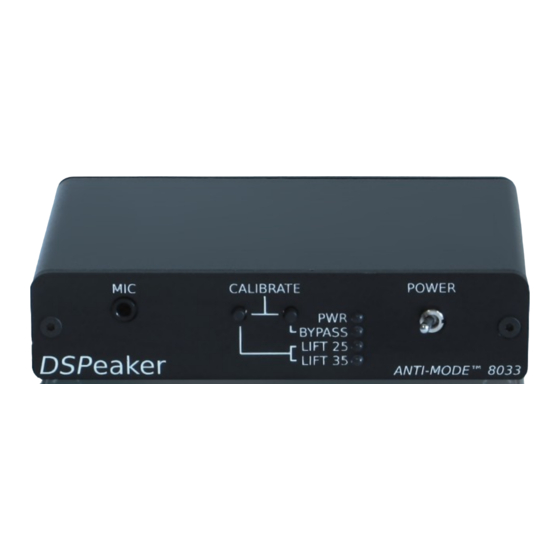
M 8033 ANTIMODE 8033 User's Manual 1. Connections and buttons 1.1. Front panel: Figure 1: ANTIMODE 8033 Front panel Microphone input jack Button A: LIFT 25 / LIFT 35 / FLAT selector Short press: Selects low frequency boost Long press: Store current low frequency boost setting Button B: BYPASS Short Presss: Disable/enable processing Long press: Begin secondphase calibration for wide area correction Buttons A & B simultaneously long press: Begin calibration PWR LED: Lit when the device is on BYPASS LED: Lit when bypassed LIFT 25 LED: Lit when 1525Hz lifting EQ and subsonic filter is on LIFT 35 LED: Lit when 2535Hz lifting EQ and subsonic filter is on POWER switch: Switches power on/off Rev. 1.6 08.01.2010 Page 4 (12) -
Page 5: Back Panel
M 8033 1.2. Back Panel: Figure 2: ANTIMODE 8033 rear panel 9V ACconnector: Input power. Note that the unit needs AC voltage! OUT 0connector: Inphase RCA out (default) OUT 180connector: Outofphase RCA out OUT0 and OUT180 connectors can be used for bridged operation of stereo amplifier LINE INconnector: Line input (subwoofer preout signal from preamplifier or A/V receiver) Rev. 1.6 08.01.2010 Page 5 (12) -
Page 6: Quick Setup Guide
M 8033 2. Quick setup guide 1. Connect the subwoofer signal preout to "LINE IN". 2. Connect the active subwoofer to "OUT 0" output. 3. Connect microphone plug to "MIC" jack and fix the microphone as close to the listening position (head of the listener) as possible. 4. Connect the power supply to "9V AC" connector and wall socket. 5. Switch ANTIMODE 8033 on. Note: All the leds on front panel are lit if the device has never been calibrated 6. Switch on the subwoofer and leave its volume setting unaltered Figure 3: Setting up ANTIMODE 8033 2.1. Before calibration With small reflex subwoofers, it is adviced to decrease their volume before calibration. If the subwoofer has a builtin lowpass or other type of filter, it should be deactivated during calibration process. It can be reactivated after calibration. Crossover and lowpass filters at ... -
Page 7: Calibration
M 8033 2.2. Calibration Press both buttons at the front panel and hold them for about three seconds. Make sure that both of the buttons are pressed and held. After about three seconds the middle LED will start flashing and calibration begins. You may now release the buttons and wait for the automatic calibration to finish. The measurement program analyzes the room four times with a frequency sweep. During the calibration, the device will adjust the output level automatically. If the microphone level in is too loud, it is automatically decreased. The calibration is quite robust, so it tolerates ... -
Page 8: Wider Area Correction
M 8033 3. Wider area correction In some situations it is more favourable to compensate the room acoustics for a larger area. In this case, the result is no longer optimal in any single listening position, but generally improved for a wider area. Before wider area correction, the normal calibration procedure described in the earlier section must be performed. The initial calibration is done with the microphone at the center of the listening area (or primary listening position within the area). AntiMode 8033 is calibrated to larger area by taking the microphone to some other point within the listening area. Pressing and holding button B, bypass (Figure 1, object 3) will initiate a single additional frequency sweep. AntiMode 8033 will use it in conjunction with the data gathered at the first calibration to create a compensation model for a larger listening area within the room. Do not accidentally press and keep both buttons at the front panel, as this will start main calibration all over again and overrides the current room data. Wider area calibration can be done multiple times and it does not lose the data from the main calibration. Thus it is easy to try different second phase calibration points for the best audible result. There are several strategies in choosing the microphone position for second phase calibration. -
Page 9: Strategy 2, "Gradient Compensation
M 8033 3.2. Strategy 2, “Gradient compensation”: When the first (main) calibration is performed to the primary listening position or to the center of the listening area, but it is difficult to find the weakest point within the listening area, gradient compensation is a good approach. Second phase calibration point for wider area correction can be found by taking the microphone from first calibration point toward the closest corner of the listening room by 4090 cm and down (toward the floor) approximately ... -
Page 10: Basic Operation
M 8033 4. Basic operation 4.1. Bypass mode If you want to compare the corrected and uncorrected operation, press the Bypass button shortly. This will switch between bypass and normal mode. The first press will put AntiMode into bypass mode, which is also indicated by the “Bypass” LED (Figure 1, object 5) on. If the Bypass mode is already active, the unit switches to normal mode instead. In bypass mode, no room corrections are active. Also the user selected lifting EQ is turned off. 4.2. Lifting EQ The Lifting EQ button rotates between three equalization modes of AntiMode 8033 and stores the setting if held longer. A brief sound is heard from subwoofer when the setting is stored. 4.2.1. “Flat” The first lifting EQ setting is no lifting, “flat.” Neither of the LEDs 'LIFT 25' nor 'LIFT 35' is lit. In this setting, the target response is flat from 5 to 148 Hz. 4.2.2. Lifting 1525Hz In lifting 1525 mode, when the LED “LIFT 25” is lit, the AntiMode will boost frequencies between 15 and 25 Hz (max. 7dB at 20Hz). This will also activate digital infasonic filter, which will filter out frequencies below 10Hz, that can be dangerous to ported subs without ... -
Page 11: Bridging
M 8033 4.3. Bridging Bridging is always done with user's own responsibility and consideration, as not all stereo amplifiers can provide bridged operation. Ordinary stereo amplifier can be bridged by using both OUT0 and OUT180 RCA outputs. (Figure 2, objects 2 and 3.). Using differential output will give 2.83 times the amplification of a single output channel. In bridging + poles of both the output channels of the power amplifier are used instead of + and . Bridging is useful as means of multiplying the power of stereo amplifier used for passive subwoofer. -
Page 12: Technical Specification
Frequency range: 5 – 160 Hz (6 dB) Lowpass: Bessel 12 dB/oct, fc = 160Hz, Q=0.5 Amplification: 1.5 x Dynamic ratio (unweighted): 90 dB Firmware features: AntiModeFilters: 24 pcs. Correction range: 16 144 Hz Frequency resolution: < 0.5 Hz Maximum attenuation: 96 dB Filter Qvalue range: Unlimited (32bit integer space) Subsonicfilter: 10 Hz (user selectable) Computation accuracy: 32/40bit integer 6. Manufacturer VLSI Solution Oy / DSPeaker Division Hermiankatu 8 B FIN33720 Tampere FINLAND Fax: +358331408288 Tel: +358331408200 Email: sales@vlsi.fi URL: http://www.dspeaker.com/ 7. Support support@dspeaker.com info@dspeaker.com Rev. 1.6 08.01.2010 Page 12 (12)
Need help?
Do you have a question about the Anti-Mode 8033 and is the answer not in the manual?
Questions and answers