
Related Manuals for Charnwood W730


Summary of Contents for Charnwood W730
-
Page 1: Operating Instructions
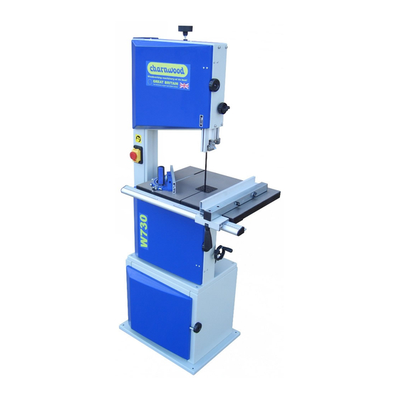
14” BANDSAW OPERATING INSTRUCTIONS MODEL: W730 Charnwood, Cedar Court, Walker Road, Bardon, Leicestershire, LE67 1TU Tel. 01530 516 926 Fax. 01530 516 929 email; sales@charnwood.net website; www.charnwood.net... - Page 2 1. Components and Parts (standard delivery ) Front 1. Upper housing door REAR 2. Setting knob for band saw blade tension 14. Quick release lever for band saw blade 3. Turn-lock fasterner, housing door 15.Setting knob for blade tracking adjustment 4.
-
Page 3: Table Of Contents
Table of contents be used as follows: Additional information. • Read these instructions before use. Components and parts (standard delivery)………..….1 Pay special attention to the safety 3. Safety Please read first! ..…....….2 information. 3.1 Specified conditions of use • These Safety ........……2 operating instructions... -
Page 4: Symbols On The Machine
Do not operate tool near inflammable cutting tool at standstill! beech, ash) can cause cancer when liquids or gases. Wear gloves when changing cutting tools. inhaled: work only with a suitable dust The saw shall only be started and collector connected to the saw. operated by persons familiar with band Risk of kickback (work piece is saws and who are at any time aware of... -
Page 5: Safety Devices
The push stick serves as an extension of the hand and protects against accidental 3.4 Safety devices contact with the saw blade. The push stick must always be used if the distance between band saw blade and a rip fence is less than 120 mm. Guide the push stick at an angle of 20°... -
Page 6: Initial Operation
With the setting knob (34) the drive belt Risk of injury! tension is corrected, if necessary When cutting with the mitre turning setting knob fence the lock handle must be firmly clockwise reduces the blade tightened. tension 6. Initial Operation turning setting knob... -
Page 7: Installing The Saw Table
6.6 Installing the Push Stick 6.2 Installing the Saw Table Check band saw blade tension (see Holder Fit limit stop screw (40) to the "Initial operation"). Note: underside of the low house . Loosen lock lever. If the saw is to be mounted on Guide saw table over the band saw Using a try square, set the table at the stand, the push stick holder can... -
Page 8: Tensioning The Band Saw Blade
6.8 Tensioning the Band Saw a dry environment. 1.5 mm Blade Operate the saw only on a power Do not pull on the power supply Danger! source matching following cable to unplug. Too much tension can requirements (see also "Technical When the saw is assembled and all cause the band saw blade to break. -
Page 9: Operation
washer then secure on upper side be set approx. 3 mm above the work with hex nut. Repeat procedure for all piece); four corners before tightening fully. after adjustments of band saw blade 7. Operation or saw table (e.g. band saw blade Danger! change, tensioning of the band saw To reduce the risk of personal... -
Page 10: Sawing
V-belt should flex approx. 10 mm). damage. To remove the band saw blade, • Close the lower housing door. guide it through Repair and maintenance work other 7.1 Sawing than described in this section should the slot in the saw table, 1. -
Page 11: Aligning The Upper Blade Guide
band saw blade. and Maintenance"); Loosen fixing screw of the upper Lift band saw tyre with a small Loosen lock nut (56). Turn setting knob (57): blade guide. screwdriver, then pull off the band Turn setting knob (57) clockwise if Align upper blade guide saw wheel. -
Page 12: Repairs
cool down for a few minutes, then Do not store the saw outdoors, in Rated no-load speed 1490±10% min unprotected areas or in damp or wet start again. Band saw blade length 2560mm locations. Band saw blade wanders off the line of Max. -
Page 13: Electric Wiring Diagram
13. Electrical wiring diagram - 12 -... - Page 14 14. Exploded view drawing and part list Band saw cabinet stand Item Drawing No. Name Q’TY Item Drawing No. Q’TY DJ350A01012 Left end panel DJ350A01015 Base GB/T17880.1 M6X13.5 Nut GB6170-86 M6 Hex nut DJ350A01014 Front bracing member GB889-86 M6 Hex. Locking nut GB97.1-85 6 Washer GB70-85 M6×35...
- Page 15 - 14 -...
- Page 16 ITEM PART NO. NAME Q'ty DJ350A04100 Lower door GB70-85 M6×16 Hex. socket set columned head bolt DJ350A04004 Spacer bushing GB889-86 M6 Locking nut GB6170-86 M4 DJ350A03102 joining block 31503035 spring plate GB12618-90 4×10 Rivet GB818-85 M4×16 Cross recessed pan head screw DJ350A03100 upper door GB894.1-86 15...
- Page 17 ITEM PART NO. NAME Q'ty DJ350A05002 Lamello plug 31503006 Setting knob GB6172-86 M8 Hex. Thin nut DJ38003004-01 Thread bolt DJ38003002 Tension pan GB6173-86 M20×1.5 Hex. Nut DJ31703010 Seat for quick release shaft DJ38003007 Quick release shaft GB6172-86 M10 Hex. Thin nut TJ315B03002-1 locking handle GB6170-86 M10...
- Page 18 ITEM PART NO. NAME Q'ty GB845-85 ST3.5×9.5 Cross recessed pan head tapping screw RTS250G04011 TJ315B03002-1 Handle TJ315B03002-2 DJ315S02001-08 Shaft RTS250G06010 Pointer GB70-85 M6X35 Hex. socket set columned head bolt RTS250G04002-2 cover board right DJ350A04001 Fence carrier extrusion 31502015 Wing bolt RTS250G04002-1 cover board left TJ25003004A-2...
Need help?
Do you have a question about the W730 and is the answer not in the manual?
Questions and answers