Table of Contents
Advertisement
Quick Links
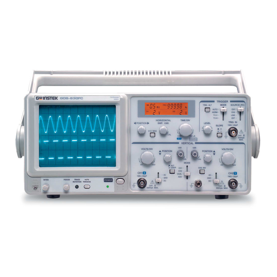
Dual Trace Oscilloscope
GOS-630FC
USER MANUAL
GW INSTEK PART NO. 82OS-630FCMA1
ISO-9001 CERTIFIED MANUFACTURER
This manual contains proprietary information, which is protected by
copyrights. All rights are reserved. No part of this manual may be
photocopied, reproduced or translated to another language without
prior written consent of Good Will company.
The information in this manual was correct at the time of printing.
However, Good Will continues to improve products and reserves the
rights to change specification, equipment, and maintenance
procedures at any time without notice.
Good Will Instrument Co., Ltd.
No. 7-1, Jhongsing Rd., Tucheng City, Taipei County 236, Taiwan.
Advertisement
Table of Contents

Related Manuals for GW Instek GOS-630FC


Summary of Contents for GW Instek GOS-630FC
- Page 1 Dual Trace Oscilloscope GOS-630FC USER MANUAL GW INSTEK PART NO. 82OS-630FCMA1 This manual contains proprietary information, which is protected by copyrights. All rights are reserved. No part of this manual may be photocopied, reproduced or translated to another language without prior written consent of Good Will company.
-
Page 2: Table Of Contents
TABLE OF CONTENTS GOS-630FC User Manual APPENDIX ..............36 Table of Contents Line Voltage & Fuse Replacement ..36 Specifications ........38 Declaration of Conformity ....40 SAFETY INSTRUCTIONS ........... 5 PRODUCT OVERVIEW ............. 10 Product Description ......10 Main Features ........11 Block Diagram ........ -
Page 3: Safety Instructions
SAFETY INSTRUCTIONS GOS-630FC User Manual Safety guidelines General • Never connect a hazardous live voltage to the AFETY INSTRUCTIONS Guideline ground side of the BNC connectors. It might lead to fire or electric shock. CAUTION • Do not place heavy objects on the instrument. • Avoid severe impacts or rough handlings that This chapter contains important safety instructions lead to damaging the instruments. that you must follow when operating the instrument and when keeping it in storage. Read • Do not discharge static electricity onto the the following instructions before operating the instruments. instrument to ensure your safety and to keep it in • Use only mating connectors, not bare wires, for best condition. the terminals. • Do not block the cooling fan opening. Safety symbols • Do not perform measurements at power These safety symbols may appear in this manual or on the ... - Page 4 • To avoid electric shock, connect the protective (Pollution Degree) EN 61010-1:2001 specifies the pollution degrees grounding conductor of the AC power cord to and their requirements as follows. The GOS-630FC falls under degree 2. an earth ground. Pollution refers to “addition of foreign matter, solid, liquid, or gaseous (ionized gases), that may produce a reduction of dielectric Fuse •...
-
Page 5: Product Overview
SAFETY INSTRUCTIONS GOS-630FC User Manual Power cord for the United Kingdom When using the instrument in the United Kingdom, make sure the RODUCT OVERVIEW power cord meets the following safety instructions. NOTE: This lead/appliance must only be wired by competent persons WARNING: THIS APPLIANCE MUST BE EARTHED IMPORTANT: The wires in this lead are coloured in accordance with the... -
Page 6: Main Features
PRODUCT OVERVIEW GOS-630FC User Manual Main Features Block Diagram High intensity The CRT incorporates high beam transmission, high intensity, and a 2kV high acceleration voltage. The CRT displays clearly readable traces even at acceleration higher sweep speeds. Wide In addition to the DC‐30MHz (‐3dB) wide bandwidth and bandwidth, the oscilloscope provides a 1mV/DIV high sensitivity. The 30MHz frequency range is sensitivity obtained by an improved triggering synchronization. Frequency A built‐in 5‐digit frequency counter offers ±0.02% Counter accuracy between 1kHz and 30MHz, and ±0.05% between 50Hz and 1kHz. Automatic Pressing the AUTO TIMEBASE key automatically timebase adjusts the sweep time to an appropriate range. adjustment Alternate Even when observing two waveforms in different triggering frequencies, both waveforms can be stably triggered using the alternate triggering mode. ... -
Page 7: Panel Overview
PANEL OVERVIEW GOS-630FC User Manual Vertical Controls the vertical scale, vertical position, display Controls mode, CH2 inversion, and alternate display mode. Trigger Controls the trigger mode, trigger level, trigger Controls ANEL OVERVIEW coupling source, trigger slope, and alternate triggering mode. Accepts the external trigger input. Input Accepts the CH1 and CH2 input signals and ground Terminals wire. Controls the input signal coupling mode. Front Panel Overview Display Controls 1 CAL Output Generates the probe compensation signal; 2Vp‐p, 1kHz, positive square wave. For probe compensation details, see page26. 2 INTEN Knob Controls the brightness of a light spot or trace in the display. 3 FOCUS Controls the focus (sharpness) of the waveforms in Detailed descriptions of each block start from the next page. ... -
Page 8: Lcd Display
PANEL OVERVIEW GOS-630FC User Manual LCD Display Horizontal Controls 1 Horizontal Controls the horizontal position of traces and light 1 CH1 POSITION Shows the CH1 vertical scale. spots. Vertical Knob Scale 2 ×10 MAG Magnifies the horizontal scale by a factor of 10. For 2 Horizontal Switch Shows the horizontal scale. horizontal magnification details, see page33. Scale 3 SWP VAR Adjusts the horizontal scale. 3 X-Y Mode Knob When turned on, indicates that the X‐Y mode is At the minimum position, the horizontal scale ... -
Page 9: Vertical Controls
PANEL OVERVIEW GOS-630FC User Manual DUAL The CH1 and CH2 signals are displayed Vertical Controls simultaneously. ADD The CH1 and CH2 signals are added or subtracted, and then the result is displayed. For CH1/CH2 addition/subtraction details, see page31. 5 VAR Knob Adjusts the vertical scale. At the minimum position, the vertical scale becomes 2.5 times wider than the original value selected by the VOLTS/DIV knob. For example, if the original scale is 1mV/DIV, the adjusted scale becomes 2.5mV/DIV. 1 VOLTS/DIV Controls the CH1/CH2 vertical scale from At the maximum (CAL) position, there is no Knob 1mV/DIV to 5V/DIV in 12 steps. change in the vertical scale. 2 Vertical Controls the vertical position of traces and light 6 CH2 INV Inverts the CH2 input signal vertically. When the POSITION spots for CH1/CH2. ... -
Page 10: Trigger Controls
PANEL OVERVIEW GOS-630FC User Manual TV-V The oscilloscope triggers when a Trigger Controls vertical video synchronization signal appears. For triggering on the field, select 2ms/DIV as the horizontal scale; for triggering on the frame (two interlaced fields), 5ms/DIV. TV-H The oscilloscope triggers when a horizontal video synchronization signal appears. For triggering on the line, select 10us/DIV as the horizontal scale. Use the SWP VAR knob to control the number of waveforms. Note • 1 Trigger ALT For TV‐V and TV‐H trigger, the When pressed, the TRIG ALT switch constantly oscilloscope responds only to Switch toggles the trigger source between CH1 and CH2 negative polarity signals. signal, so that both signals can be clearly viewed. The TRIG ALT switch works when the vertical mode is in the DUAL position and also the trigger source is in the CH1 or CH2 position. • Note The oscilloscope cannot trigger ... -
Page 11: Input Terminals
PANEL OVERVIEW GOS-630FC User Manual 4 Trigger Selects the triggering slope. Input Terminals SLOPE When in the “+” position ( ), the oscilloscope Switch triggers when the positive slope of the trigger source signal crosses the trigger level. When in the “–” position ( ), the oscilloscope triggers when the negative slope of the trigger source signal crosses the trigger level. 1 CH 1 (X) Accepts the CH1 input signal. In X‐Y mode, the Input CH1 input signal becomes the X‐axis. Terminal 2 AC/GND/ Selects the coupling mode for the input signal. DC Switch 5 Trigger Selects the signal on which the oscilloscope sweeps. The oscilloscope block DC components SOURCE included in the input signal. ... -
Page 12: Rear Panel Overview
PANEL OVERVIEW GOS-630FC User Manual Rear Panel Overview ETUP Default Settings Before powering up the oscilloscope, set up the front panel as follows. POWER Switch Off 1 FUSE & Line Holds the AC mains fuse and selects the AC line INTEN Knob Center Voltage voltage, 115V or 230V. Selector FOCUS Knob Center 2 AC Power Accepts the AC power cord. Input Vertical MODE CH1 Connector... -
Page 13: Set Up & Probe Compensation
SETUP GOS-630FC User Manual CH1/CH2 CAL Set up & Probe Compensation VARIABLE Knob Follow these steps and properly set up the oscilloscope, make sure it CH1/CH2 AC is functional, and compensate the probe. Coupling Switch Power on Press the Power switch and turn on the oscilloscope’s power. The Trigger CH1 LED lights when the power is on. SOURCE Switch The trace line starts to appear after Trigger SLOPE 20 – 30 seconds. + (Positive slope) Switch Intensity Use the INTEN knob and FOCUS TRIG ALT Released (alternating trigger and focus knob to adjust the trace line ... -
Page 14: Measurement
SETUP GOS-630FC User Manual Vertical Use the CH1 VOLTS/DIV knob adjustment and CH1 vertical POSITION knob to adjust the vertical scale and EASUREMENT position of the waveform. Horizontal Use the CH1 TIME/DIV knob and adjustment CH1 horizontal POSITION knob to adjust the horizontal scale and Single Channel (Basic) Measurement position of the waveform. Steps 1. Connect the input signal to the CH1 or CH2 terminal. Probe Adjust the compensation point on the probe so compensa- that the waveform becomes square. 2. Select the vertical coupling tion between AC (DC components are blocked) or DC (all signal components appear). 3. Configure the trigger settings. For details, see page19. Under compensation... -
Page 15: Dual Channel Measurement
MEASUREMENT GOS-630FC User Manual 6. Use the vertical ALT/CHOP Dual Channel Measurement switch to select how the two waveform appear on the Steps display: alternately (ALT mode) 1. Connect both CH1 and CH2 signals to the input terminals. or simultanouesly (CHOP mode). See page17 for details. 2. Select the vertical coupling 7. If necessary, use the between AC (DC components VOLTS/DIV knob and vertical are blocked) or DC (all signal POSITION knob to adjust the components appear) for both vertical scale and position of channels. the waveform. 3. Configure the trigger settings. 8. If necessary, use the TIME/DIV For details, see page19. knob and horizontal POSITION Make sure the trigger SOURCE knob to adjust the horizontal switch is in either the CH1 or scale and position of the ... -
Page 16: Waveform Addition/Subtraction
MEASUREMENT GOS-630FC User Manual Waveform Addition/Subtraction X-Y Mode Steps Background The X‐Y mode compares the amplitude of two 1. Make sure both CH1 and CH2 signals (CH1 and CH2), one as X‐axis (CH1) and waveforms appear on the the other as Y‐axis (CH2). The X‐Y mode is useful display. For details, see page29. for measuring the phase difference of two signals, 2. Set the vertical MODE switch to video color patterns, and frequency response. the ADD position. The two Steps 1. Make sure both CH1 and CH2 waveforms are added and waveforms appear on the appear on the display as a display. For details, see page29. single waveform. 2. Move the TIME/DIV knob to the 3. To subtract the CH2 signal from X‐Y position. the CH1 signal, invert the CH2 signal by pressing the CH2 INV switch. 3. The CH1 and CH2 signals appear in the X‐Y ... -
Page 17: Waveform Magnification
MEASUREMENT GOS-630FC User Manual 5. To adjust the Y‐axis position and deflection, use the CH2 vertical POSITION knob (position) and CH2 VOLTS/DIV knob (deflection). Waveform Magnification Background The probe waveform is distorted. The oscilloscope can magnify the waveform by ten times in the horizontal direction. The You might need to compensate the probe. For details, see page26. magnification is useful for observing complex Note that frequency accuracy and duty factor are not specified for signals. the probe compensation waveform and therefore it should not be Steps 1. Make sure the waveform is shown on the used for reference purpose. display. The trace line does not appear on the display. 2. Press the ×10 MAG switch. The ... -
Page 18: Appendix
GOS-630FC User Manual The input signal does not appear on the display. Check the following settings. PPENDIX • The coupling mode is not set at the GND mode, in which the waveform does not appear on the display. See page22 for details. • The appropriate trigger source is selected. See page19 for details. The oscilloscope accuracy does not match the specifications. Line Voltage & Fuse Replacement Make sure the oscilloscope is powered on for at least 30 minutes, within +20°C – +30°C. This is necessary to stabilize the oscilloscope. 1. Take off the power cord. For more information, contact your local dealer, Good Will Instruments website www.gwinstek.com.tw, or marketing@goodwill.com.tw. 1 1 5 2. -
Page 19: Specifications
APPENDIX GOS-630FC User Manual Specifications 4. If necessary, replace the fuse that is attached to the fuse holder. The specifications apply when the GOS‐630FC is powered on for at 1 1 5 least 30 minutes under +20°C – +30°C. Vertical Sensitivity 1mV/DIV to 2mV/DIV: ±5% 5mV/DIV to 5V/DIV: ±3% accuracy Bandwidth 1mV/DIV to 2mV/DIV: DC to 7MHz 5mV/DIV to 5V/DIV: DC to 30MHz 5. Push the fuse holder back into the socket. AC coupling >... -
Page 20: Declaration Of Conformity
APPENDIX GOS-630FC User Manual 0.2µS to 0.5S/DIV, ±3% Horizontal Axis Sweep time Declaration of Conformity accuracy x10MAG accuracy ±5% (20/50nS uncalibrated) ±3%, x10:±5% (20/50nS uncalibrated) Linearity X-Y Mode Sensitivity Same as vertical axis GOOD WILL INSTRUMENT CO., LTD. (1) No.7-1, Jhongsing Rd., Tucheng City, Taipei County, Taiwan...
Need help?
Do you have a question about the GOS-630FC and is the answer not in the manual?
Questions and answers