Allied Telesis AT-FS202 Installation Manual
Allied telesyn international fast ethernet series switches installation guide
Hide thumbs
Also See for AT-FS202:
- Installation manual (88 pages) ,
- Datasheet (2 pages) ,
- Datasheet (2 pages)

Related Manuals for Allied Telesis AT-FS202


Summary of Contents for Allied Telesis AT-FS202
-
Page 1: Installation Guide
AT-FS201 AT-FS202 AT-FS202SC/FS1 AT-FS202SC/FS2 AT-FS202SC/FS3 AT-FS202SC/FS4 Fast Ethernet Series Switches Installation Guide PN 613-10761-00 Rev E... - Page 2 Copyright © 2004 Allied Telesyn International, Corp. All rights reserved. No part of this publication may be reproduced without prior written permission from Allied Telesyn International, Corp. Ethernet is a registered trademark of Xerox Corporation. All other product names, company names, logos or other designations mentioned herein are trademarks or registered trademarks of their respective owners.
-
Page 3: Electrical Safety And Emission Compliance Statement
At time of installation, the Fiber Optic Lasers comply with FDA Radiation Performance Standard 21CFR Subchapter J, applicable at date of manufacture. This is a “Class 1 LED Product” (AT-FS201, AT-FS202 models) U.S. Federal Communications Commission Industry Canada EN55022 Class A... - Page 4 Electrical Safety and Emission Compliance Statement Important: Appendix B contains translated safety statements for installing this equipment. When you see the safety statement in your language. Wichtig: Anhang B enthält übersetzte Sicherheitshinweise für die Installation dieses Geräts. Wenn Sie den übersetzten Sicherheitshinweis in Ihrer Sprache nach. Vigtigt: Tillæg B indeholder oversatte sikkerhedsadvarsler, der vedrører installation af dette udstyr.
-
Page 5: Table Of Contents
Store and Forward ... 8 External AC/DC Power Adapter ... 8 Network Topologies ... 8 Chapter 2 Installing the Switch ... 11 Verifying Package Contents ... 11 Planning the Installation ... 12 Selecting a Site ... 14 Installing the Switch ... 15... - Page 6 Table of Contents Chapter 3 Troubleshooting ... 19 Appendix A Technical Specifications ... 21 Physical ... 21 Temperature ... 21 Electrical Rating ... 21 Agency Certifications ... 22 Fiber Optic Port Specifications ... 22 Pinout Assignments ... 24 Appendix B Translated Safety and Emission Information ...
-
Page 7: Welcome To Allied Telesyn
Welcome to Allied Telesyn This guide contains instructions on how to install the AT-FS20x and AT-FS202SC/FSx Series switches. Where to Find Web-based Guides The Allied Telesyn web site at www.alliedtelesyn.com offers you an easy way to access the most recent documentation, software, and technical information for all of our products. -
Page 8: Contacting Allied Telesyn
Welcome to Allied Telesyn Contacting Allied Telesyn This section provides Allied Telesyn contact information for technical support as well as sales or corporate information. Online Support You can request technical support online by accessing the Allied Telesyn Knowledge Base from the following web site: www.alliedtelesyn.com/kb. You can use the Knowledge Base to submit questions to our technical support staff and review answers to previously asked questions. -
Page 9: Chapter 1 Description
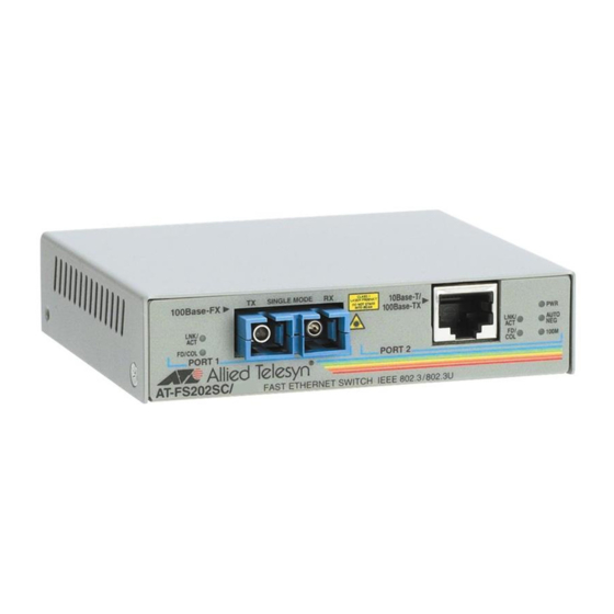
Each switch features a 100Base-FX fiber optic port and a 10Base-T/ 100Base-TX twisted-pair port. The fiber optic port has either a SC or ST connector and a maximum operating distance of 2 kilometers (1.2 miles) to... - Page 10 Figure 1 illustrates the front panel of an AT-FS20x Series switch. 100Base-FX LNK/ FD/COL PORT 1 AT-FS202 FAST ETHERNET SWITCH IEEE 802.3 / 802.3U Figure 1 AT-FS20x Series Front Panel (AT-FS202 Model) Figure 2 illustrates a front panel of an AT-FS202SC/FSx Series switch. 100Base-FX LNK/ FD/COL PORT 1 AT-FS202SC/FS4...
- Page 11 Table 1 lists the maximum operating distances for the switches. Table 1 Maximum Operating Distances Model Connector AT-FS201 AT-FS202 FS202SC/ FS202SC/ FS202SC/ FS202SC/ 1. Maximum distance for 100 Mbps optical datalinks is dependent on the following factors: type of optical fiber, duplex mode of both end-nodes, and maximum optical loss budget for each of the optical fiber at the operating optical wavelength.
-
Page 12: Key Features
Table 2 defines the LEDs for the switches. Color Green LNK/ACT Green Blinking Table 2 Status LEDs Description Power is applied to the switch. A valid link has been established on the port. Data is being received or transmitted on the port. -
Page 13: Twisted-Pair Port
10 Mbps or 100 Mbps operation. You can set the port speed manually or, since the port is IEEE 802.3u Auto-Negotiation compliant, you can allow the switch to set the port speed automatically. With Auto-Negotiation, the speed of the port is set automatically by the switch after it determines the speed of the end-node connected to the port. -
Page 14: Auto Mdi/Mdi-X
For example, if a port on a switch is connected to a port on a bridge, which is typically wired as MDI, the port on the switch automatically configures itself as MDI-X. This feature allows you to use either crossover cables or straight-through cables when connecting a device to the twisted-pair port. -
Page 15: Switch Performance
Negotiation automatically sets the port’s speed and duplex mode. MAC Address Table Up to 4,000 MAC addresses can be stored in the switch’s MAC address table. After power-up, the switch’s self-learning feature learns new addresses in real-time. If the source address of an incoming packet is not found in the MAC address table, the switch updates the table with the new address. -
Page 16: Store And Forward
For example, if the packet entering from Port 1 is destined for an end-node on Port 2, the switch forwards the frame as long as the frame does not contain any errors. If the packet from Port 1 is destined for an end-node also connected to Port 1, the packet is discarded. - Page 17 Figure 4 illustrates a topology using one AT-FS202 switch to interconnect two small networks of stackable hubs. AT-8026C Figure 4 Typical Configuration Using the AT-FS202 Switch AT-FS20x Series Installation Guide AT-FS202 AT-FS708 Twisted Pair Fiber Optic...
- Page 18 Description...
-
Page 19: Chapter 2 Installing The Switch
Series switches. These switches can be installed on a desktop or in an AT-MCR12 chassis. The procedures provided in this chapter are for installation on a desktop. To install a switch in the AT-MCR12 chassis, see the AT-MCR12 Chassis Installation Guide. -
Page 20: Planning The Installation
The end-node connected to the 10Base-T/100Base-TX twisted-pair port can operate at either 10 Mbps or 100 Mbps. ❑ The end-node connected to a port on the switch can be a network adapter card, repeater, router, hub, or another switch. ❑... - Page 21 Model AT-FS202 AT-FS202SC/FS1 AT-FS202SC/FS2 AT-FS202SC/FS3 AT-FS202SC/FS4 1. Maximum distance for 100 Mbps optical datalinks is dependent on the following factors: type of optical fiber, duplex mode of both end-nodes, and maximum optical loss budget for each of the optical fiber at the operating optical wavelength.
-
Page 22: Selecting A Site
One switch inline Two switches Inline 1. The total distance of the fiber optic lengths cannot exceed the limits stated in the table. Each switch used inline within a single collision domain reduces the overall segment length by 40 meters (131 feet). -
Page 23: Installing The Switch
See “Verifying Package Contents” on page 11. Attach the four protective feet (provided) to each corner of the bottom of the unit. Configure the DIP switches on the rear of the switch. See Table 6, “DIP Switch Settings,” on page 15 for the settings. Switch... - Page 24 Mode Auto Neg Up Caution After you change the speed or duplex mode of the switch, you must power cycle (shut down and restart) the switch for the new settings to take affect. Place the switch on a secure, level surface, leaving ample space around the switch for ventilation.
-
Page 25: Warranty Registration
10. Connect the twisted-pair cable (or cables) to the end node. See Table 7 for information about setting the duplex mode. You must set the AT-FS20x switch and the end node to auto negotiate or make their port speeds match. - Page 26 Installing the Switch...
-
Page 27: Chapter 3 Troubleshooting
Note Whenever the speed and/or duplex mode are changed during or after power ON, power OFF then power back ON the switch to load the new configuration. If the PWR LED is OFF, do the following: ❑... - Page 28 For the fiber optic port specifications, refer to refer to Table 1 on page 3 and for the cable types, refer to Table 3 on page 12, Table 4 on page 12, or Table 5 on page 14.
-
Page 29: Appendix A Technical Specifications
Appendix A Technical Specifications Physical Dimensions: Weight: Temperature Maximum Operating: Maximum Storage: Relative Humidity: Operating Altitude: Electrical Rating Input Supply Voltage: Maximum Current: Power Consumption: W x D x H 10.5 cm x 9.5 cm x 2.5 cm (4.12 in x 3.75 in x 1.0 in) 294 g (10.4 oz) 0°... -
Page 30: Agency Certifications
Fiber Optic Port Specifications Tables 7 through 10 list the specifications for the fiber optic port. Fiber Model Type AT-FS201 & AT-FS202 AT-FS202SC/ AT-FS202SC/ AT-FS202SC/ AT-FS202SC/ 1. MMF = Multimode Fiber / SMF = Single-mode Fiber. 2. The launch power is measured at one meter from the transmitter. - Page 31 Fiber Fiber Optic Model Type Diameter (microns) AT-FS201 50/125 & AT-FS202 62.5/125 9/125 FS202SC/ 9/125 FS202SC/ 9/125 FS202SC/ 9.125 FS202SC/ 1. MMF = Multimode Fiber / SMF = Single-mode Fiber. Fiber Model Type AT-FS201 & 50/125 AT-FS202 62.5/ AT-FS202SC/ 9/125...
-
Page 32: Pinout Assignments
Technical Specifications Fiber Model Type AT-FS202SC/ 9/125 AT-FS202SC/ 9/125 1. MMF = Multimode Fiber / SMF = Single-mode Fiber. 2. The recommended minimum range is stated in all cases where the maximum transmitter output power exceeds the receivers saturation level. This is to prevent blinding or burning out of the optical receiver on the far-end node. - Page 33 Table 12 lists the 10Base-T/100Base-TX connector pins and their signals when the port is operating in either MDI or MDI-X configuration. MDI-X (Default) AT-FS20x Series Installation Guide Table 12 RJ-45 Pinouts Signal Signal...
- Page 34 Technical Specifications...
-
Page 35: Translated Safety And Emission Information
Appendix B Translated Safety and Emission Information Important: This appendix contains multiple-language translations for the safety statements in this guide. Wichtig: Dieser Anhang enthält Übersetzungen der in diesem Handbuch enthaltenen Sicherheitshinweise in mehreren Sprachen. Vigtigt: Dette tillæg indeholder oversættelser i flere sprog af sikkerhedsadvarslerne i denne håndbog. - Page 36 At time of installation, the Fiber Optic Lasers comply with FDA Radiation Performance Standard 21CFR Subchapter J, applicable at date of manufacture. This is a “Class 1 LED Product” (AT-FS201, AT-FS202, AT-FS203 models) Safety Lightning Danger Danger: Do not work on equipment or cables during periods of lightning activity.
- Page 37 USA/Canada Use a UL Listed/CSA Certified AC adapter of DC 12V, 500mA. Europe - EU Use TÜV licensed AC adapter of DC 12V, 500mA. Use a UK Safety Approved AC adapter of DC 12V, minimum 500mA. Operating Temperature: This product is designed for a maximum ambient temperature of 40 degrees C.
- Page 38 Translated Safety and Emission Information Standarder: Dette produkt tilfredsstiller de følgende standarder. Radiofrekvens forstyrrelsesemission Advarsel: I et hjemligt miljø kunne dette produkt forårsage radio forstyrrelse. Bliver det tilfældet, påkræves brugeren muligvis at tage tilstrækkelige foranstaltninger. Immunitet Advarsel: Dette produkt skal bruges med afskærmede kabler for at overholde bestemmelserne vedrørende udstråling og støjimmunitet.
- Page 39 Waarshuwing Klasse-1 laser produkt. Waarchuwing Neit in de straal staren. Dit is een “Klasse 1 LED-produkt” Veiligheid Gevaar Voor Blikseminslag Gevaar: Niet aan toestellen of kabels werken bij bliksem. Ventilatiegaten niet blokkeren. Stroom mag alleen via de adapter naar het apparaat toegevoerd worden. Europe - EU Gebruik een door TÜV gekeurde wisselstroomadapter van 12 Volt gelijkstroom, 500 milliampères.
- Page 40 Translated Safety and Emission Information Température De Fonctionnement Ce matériel est capable de tolérer une température ambiante maximum de 40 degrés Celsius. Pour Tous Pays: Installer le matériel conformément aux normes électriques nationales et locales. Standardit: Tämä tuote on seuraavien standardien mukainen. Radioaaltojen häirintä...
- Page 41 Standard: Questo prodotto è conforme ai seguenti standard. Emissione RFI (interferenza di radiofrequenza) Avvertenza: in ambiente domestico questo prodotto potrebbe causare radio interferenza. In questo caso potrebbe richiedersi all'utente di prendere gli adeguati provvedimenti. Immunità Avvertenza: questo prodotto, se utilizzato con cavi schermati, è conforme alle norme sulle emissioni e sull’immunità.
- Page 42 Translated Safety and Emission Information Laser Advarsel Laserprodukt av klasse 1. Advarsal Stirr ikke på strålen. Dette er et “Klasse 1 LED produkt” Sikkerhet Fare For Lynnedslag Fare: Arbeid ikke på utstyr eller kabler i tordenvær. Blokker Ikke Luftventilene All strømtilførsel må komme fra adapteren. Europe - EU Benytt TÜV-godkjent AC-adapter på...
- Page 43 Temperatura De Funcionamento Este produto foi projetado para uma temperatura ambiente máxima de 40 graus centígrados. Todos Os Países: Instale o produto de acordo com as normas nacionais e locais para instalações elétricas. Estándares: Este producto cumple con los siguientes estándares. Emisión RFI Advertencia: en un entorno doméstico, este producto puede causar radiointerferencias, en cuyo caso, puede requerirse del usuario que tome las...
- Page 44 Translated Safety and Emission Information Elsäkerhet Laser Varning! Laserprodukt av klass 1. Varning! Laserstrålning när enheten är öppen. Detta är en “Klass 1 lysdiodprodukt” Säkerhet Fara För Blixtnedslag Fara: Arbeta ej på utrustningen eller kablarna vid åskväder. Blockera Inte Luftventilerna. Endast anslutningsenheten får vara kraftkälla till centralen.
Need help?
Do you have a question about the AT-FS202 and is the answer not in the manual?
Questions and answers