Advertisement
Advertisement
Table of Contents

Related Manuals for Rockford Fosgate Power T5652-S


Summary of Contents for Rockford Fosgate Power T5652-S
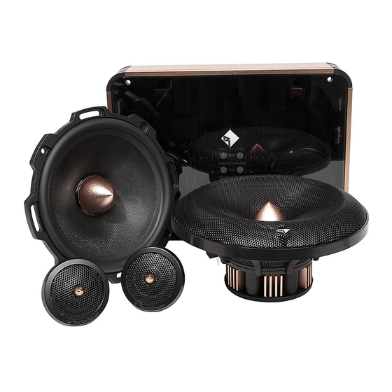
- Page 3 COMPONENT SPEAKERS T5652-S Installation & Operation...
- Page 4 16 Limited Warranty Information ©2011 Rockford Corporation. All Rights Reversed. ROCKFORD FOSGATE and associated logos where applicable are registered trademarks of Rockford Corporation in the United States and/or other countries. All other trademarks are the property of their respective owners. Specifications subject to change without notice.
-
Page 5: Specifications
2.79” (71.0mm) Grille/Trim Ring Adaptor Plate See pages 6-7 for additional dimensions CEA 2006 Power ratings on Rockford Fosgate amplifiers conform to CEA-2006 industry standards. These guidelines mean your amplifier’s output power ratings are REAL POWER numbers, not inflated marketing ratings. - Page 6 Specifications T5 - Mid-Bass 6.69" (170.0mm) 4.37" (111.0mm) 6.18" 7.14" (157.0mm) 0.95" (181.0mm) Diameter (24.0mm) 3.22" (82.0mm) 2.79" (71.0mm) 5.67" (144.0mm) T5 - Tweeter 2.31" (59.0mm) 0.63" (16.0mm) 0.41" (10.5mm) 0.66" (17.0mm) Mounting Options Surface/Angle Mount 1.7" 2.3" (43mm) (58mm) 1.5"...
- Page 7 Specifications T5 - Crossover 10.12" (257.0mm) 7.40" (188.0mm) 2.13" (54.0mm) illus.-1.2...
-
Page 8: Installation Considerations
Installation Contents 5. On models with slotted holes, fit the speaker into the cutout and install the screws in the slots at the top and bottom. This will allow • (1) Pair Power T5 mid-bass speakers you to rotate the speaker to match the remaining mounting holes. •... -
Page 9: Installation
Installation Wiring Power/Ground illus.-3.1 1. Use illustration for proper connection and be sure to maintain polarity. Red wire is connected to switched 12V source and Black wire is connected to chassis ground. 2. Connect the Power/Ground harness to either RF Link ports. Chasis Ground (Black) NOTE: Without a 12V source the crossover will still pass signal. -
Page 10: System Setup
System Setup Tweeter Position A Tweeter Level: set by selecting the TL button until the LED above +2 is illuminated. TWEETER LEVEL The tweeter is positioned low and together in relation Tweeter Phase: set by selecting the TP button until the (dB) to the mid-range. -
Page 11: Troubleshooting
Troubleshooting Troubleshooting All the LED’s are illuminated on the Remote Tuning Module when tethered. NOTE: If you are having problems after installation follow the Trouble- shooting procedures below. 1. Verify that Remote Tuning Module functions correctly when docked. See Step 3. No LED’s illuminated on the Remote Tuning Module when docked. -
Page 12: Warranty
What is Covered This warranty applies only to Rockford Fosgate products sold to consumers by Authorized Rockford Fosgate Dealers in the United States of America or its possessions. Product purchased by consumers from an Authorized Rockford Fosgate Dealer in another country are covered only by that country’s Distribu- tor and not by Rockford Corporation.
Need help?
Do you have a question about the Power T5652-S and is the answer not in the manual?
Questions and answers