
Related Manuals for BK Precision 9115


Summary of Contents for BK Precision 9115
- Page 1 Model: 9115, 9115-AT, 9116 Multi-Range DC Power Supply USER MANUAL 99 Washington Street Melrose, MA 02176 Phone 781-665-1400 Toll Free 1-800-517-8431 Visit us at www.TestEquipmentDepot.com...
-
Page 2: Safety Summary
Safety Summary The following safety precautions apply to both operating and maintenance personnel and must be followed during all phases of operation, service, and repair of this instrument. Before applying power to this instrument: • Read and understand the safety and operational information in this manual. •... - Page 3 Do not use this instrument in an electrical environment with a higher category rating than what is specified in this manual for this instrument. You must ensure that each accessory you use with this instrument has a category rating equal to or higher than the instrument's category rating to maintain the instrument's category rating.
- Page 4 Do not operate the instrument in the presence of flammable gases or vapors, fumes, or finely- divided particulates. The instrument is designed to be used in office-type indoor environments. Do not operate the instrument • In the presence of noxious, corrosive, or flammable fumes, gases, vapors, chemicals, or finely-divided particulates.
- Page 5 Clean the instrument only as instructed Do not clean the instrument, its switches, or its terminals with contact cleaners, abrasives, lubricants, solvents, acids/bases, or other such chemicals. Clean the instrument only with a clean dry lint-free cloth or as instructed in this manual. Not for critical applications This instrument is not authorized for use in contact with the human body or for use as a component in a life-support device or system.
- Page 6 Fuse replacement must be done by qualified service-trained maintenance personnel who are aware of the instrument's fuse requirements and safe replacement procedures. Disconnect the instrument from the power line before replacing fuses. Replace fuses only with new fuses of the fuse types, voltage ratings, and current ratings specified in this manual or on the back of the instrument.
- Page 7 • Do not obstruct cooling air flow to the instrument. • Do not place a hot soldering iron on the instrument. • Do not pull the instrument with the power cord, connected probe, or connected test lead. Do not move the instrument when a probe is connected to a circuit being tested.
-
Page 8: Compliance Statements
Compliance Statements Disposal of Old Electrical & Electronic Equipment (Applicable in the European Union and other European countries with separate collection systems) This product is subject to Directive 2002/96/EC of the European Parliament and the Council of the European Union on waste electrical and electronic equipment (WEEE), and in jurisdictions adopting that Directive, is marked as being put on the market after August 13, 2005, and should not be... -
Page 9: Ce Declaration Of Conformity
CE Declaration of Conformity The power supply meets the requirements of 2006/95/EC Low Voltage Directive and 2004/108/EC Electromagnetic Compatibility Directive with the following standards. Low Voltage Directive EN61010-1: 2001 EMC Directive EN 61000-3-2: 2006 EN 61000-3-3: 1995+A1: 2001+A2: 2005 EN 61000-4-2 / -3 / -4 / -5 / -6 / -11 EN 61326-1: 2006 viii... -
Page 10: Safety Symbols
Safety Symbols Refer to the user manual for warning information to avoid hazard or personal injury and prevent damage to instrument. Electric Shock hazard On (Supply). This is the AC mains connect/disconnect switch on the front of the instrument. Off (Supply). This is the AC mains connect/disconnect switch on the front of the instrument. -
Page 11: Table Of Contents
Table of Contents Safety Summary ....................i Compliance Statements ......................vii Safety Symbols ..........................ix General Information ..................1 Product Overview ......................1 Package Contents ......................1 Product Dimensions ......................2 Front Panel Overview ....................... 3 Front Panel Description ......................3 Rear Panel Overview ...................... - Page 12 Program Sequence Mode (List mode) ................34 Configure Sequence Parameters ................... 35 Configure Program (List) ....................... 38 Recall and Run Program ......................41 9115-AT Automotive Test Functions ................42 DIN 40839 Parameters ......................42 ISO 16750-2 Parameters ....................... 44 Configure Voltage Slope ....................50 Key Lock ..........................
- Page 13 Troubleshooting Guide ................56 General ..........................56 Remote Control ........................56 Specifications ..................... 57 Calibration ....................58 SERVICE INFORMATION ..................59 LIMITED ONE-YEAR WARRANTY ................ 60...
-
Page 14: General Information
B&K Precision models 9115, 9115-AT, and 9116 are multi-range single output high power supplies with the capability of producing up to 80 V or 60 A (9115/9115-AT) and 150 V or 30 A (9116) at a maximum power output of 1200 W. With an easy-to-read VFD display, user-friendly controls and a numeric keypad that allows for easy configurations from the front panel. -
Page 15: Product Dimensions
1.3 Product Dimensions The 9115, 9115-AT, and 9116 power supply’s dimensions (WxHxD) are approximately 414.5 mm x 44.5 mm x 483.2 mm (16.29” x 1.75” x 19.02”). It is designed to fit in a standard 19-inch rackmount and is of 1U size. -
Page 16: Front Panel Overview
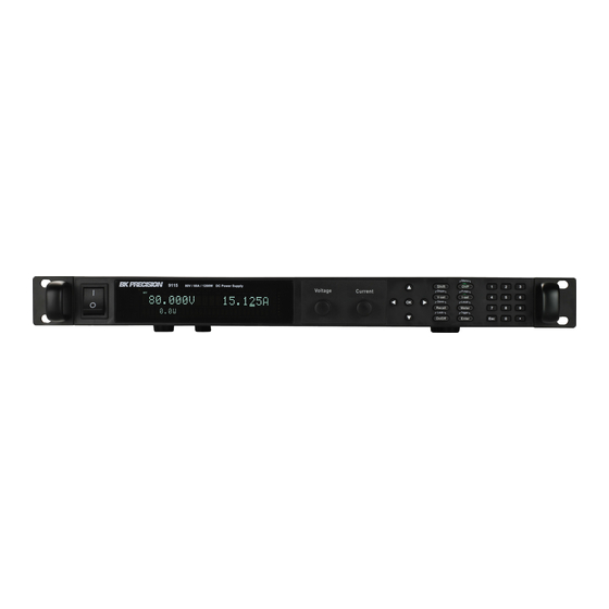
1.4 Front Panel Overview Figure 1.3 - Front Panel for 9115/9115-AT/9116 Front Panel Description Power On/Off switch VFD display Voltage adjust knob Current adjust knob Up/Down/Left/Right arrow keys Used to adjust cursor location and selecting menu items. On/Off / Lock button Control the output state or locks the front panel button. - Page 17 Shift key Enables access to secondary functions of some buttons (These functions are labeled in white) OK button (same as Enter button)
-
Page 18: Rear Panel Overview
1.5 Rear Panel Overview Figure 1.4 - Rear Panel for 9115/9115-AT/9116 Rear Panel Description Analog Control Interface Output Terminal Rear Cooling Fan GPIB Interface USB Interface RS-232 Interface AC Input Receptacle Fuse Box RS-485 Interface Remote Sense Terminals... -
Page 19: Display Overview
1.6 Display Overview OFF CC CV Addr Error Trig Prot * Shift 80.000V 12.000A = 85.000 V 0.0 W Figure 1.5 – Display Overview Display Description Setting/Measured Voltage Measured Power Output Settings Display Displays parameter settings such as OVP, P-max, Rise/Fall Setting/Measured Current Indicates output is disabled Indicates constant current (CC) operation... -
Page 20: Getting Started
2 Getting Started Before connecting and powering up the instrument, please review and go through the instructions in this chapter. 2.1 Input Power and Fuse Requirements Input Power Before connecting to an AC outlet or external power source, be sure that the power switch is in the OFF position and verify that the AC power cord, including the extension line, is compatible with the rated voltage/current and that there is sufficient circuit capacity for the power supply. -
Page 21: Fuse Requirements
Connection of this power supply to an AC power source should be made by a qualified electrician or other qualified personnel. Incorrect wiring may damage the power supply or cause a fire hazard Fuse Requirements An AC input fuse is necessary when powering the instrument. Refer to the table below for the fuse requirements. -
Page 22: Preliminary Check
from resistances in the wires. Rear Output Terminal Hex Key Screw 10mm 10mm 10mm Figure 2.1 - Rear Output Terminal Due to the high current rating of the power supply, proper wire sizes are necessary for safe connectivity and to prevent wires from overheating. Refer to the table below as a reference for proper wire sizes according to the amount of current used for operation: Table 2.2 - Wire Gauge Rating Imax(A) -
Page 23: Self-Test Errors
System Selftest ..Self-test Errors The following errors will be displayed if self-test did not complete successfully: Error Message on Display Description EEPROM FAILURE The internal EEPROM is corrupted or damaged. Config Data Lost The last operation data within the EEPROM is lost. Calibration Data Lost Calibration data within the EEPROM is lost. -
Page 24: Check Model And Firmware Version
Power Info . . . Model: BK9115 Ver: 0.02 – 0.01 3. The model is shown above as BK 9115, and the firmware version is shown as 0.02 – 0.01. 4. Press twice to exit the menu and return to the normal display. -
Page 25: Front Panel Operation
Show model, firmware version, and serial number. Available on models 9115/9115-AT and 9116 only Available on model 9115-AT only (LIST mode can be found in the menu) How to Access the Menu Before using the instrument, it is important to be familiarized with its menu structure and learn how to view or change settings and parameters. -
Page 26: Configure Voltage And Current Output
1. From the normal display, press and press to enter the menu. 2. The selected item will be blinking. Use keys to move through the menu selections. 3. When the desired menu section is blinking, press to access its menu settings. 4. -
Page 27: Setting Current
Note: To see the changes to the setting voltage, be sure the display is not showing the measured voltage. This can be checked by looking at the button backlight. If it is not lit, display is showing setting voltage. Setting Current Follow the steps below to set the output current: 1. - Page 28 Figure 3.1 – Local Sense Connection Diagram DO NOT disconnect the wires if remote sense is not used. Doing so will cause erratic behavior and may damage the power supply under certain conditions. Never connect any power source into any of the four terminals at any time during operation.
-
Page 29: Protection Settings
Rear Sense Terminal Rear Output Terminal Figure 3.2 – Remote Sense Connection Diagram DO NOT at any time disconnect the wires from the Vs+ and Vs- terminals to the DUT while output is enabled (ON). Doing so may damage the power supply and cause unstable output. -
Page 30: Configure Maximum Power Limit
5. To disable OVP at any time, just press twice. When it is disabled, the backlight will disappear. When OVP protection is tripped, the following screen will display: Prot 80.000VOVP 12.000A 0.0 W To clear the trip status, press once. Configure Maximum Power Limit Follow the steps below to set the maximum power limit: 1. -
Page 31: System Menu
Prot 80.000VOPP 12.000A 0.0 W To clear the trip status, press once. 3.3 SYSTEM Menu All setup procedures and settings explained in this section can be accessed from the SYSTEM menu. To access this menu, press and press . When SYSTEM is blinking, press Restore Factory Default Settings All instrument settings can be reset back to their factory default values by doing the following: Restoring the instrument to factory default will change all current instrument... -
Page 32: Configure Power-On State
Power-On Load Setup External Control 10v-M Limit Vmin = 0.000V, Vmax = 81.000V Online Setup Output Disabled Configure Power-On State The initial power-On state of the power supply can be configured by following the steps below: 1. From the SYSTEM menu, select Power-On and press 2. - Page 33 to store settings (0 to 9). The memory group must be selected from the menu first, before settings can be saved within the group. Select Storage Group 1. From the SYSTEM menu, browse and select Memory and press . The following screen will appear.
-
Page 34: Enable/Disable Key Sound
1. Press . Notice the button will be lit and the cursor on the display will disappear. This indicates Recall mode. Instrument settings can only be recalled when the instrument enters this mode. 2. Use the keypad to enter the memory location you want to recall. Enter between 0 to 9. 3. - Page 35 RS-232 Follow the steps below to configure the power supply for RS-232 operation: 1. From the SYSTEM menu, browse and select Communication and press 2. Select RS-232(Def) and press to set to RS-232 for remote communication. The following display will be shown: RS232 48 00 , 8 , N , 1 , Add r .
- Page 36 GPIB Follow the below instructions to select GPIB interface for remote operation. 1. From the SYSTEM menu, browse and select Communication and press 2. Select GPIB and press to set to GPIB for remote communication. 3. The display will give a prompt to select an Address. This is the GPIB address to which the power supply will be assigned to.
-
Page 37: Return Meter
6. Select Addr… and press . You will be prompted to enter an address. Use current adjust knob or numeric keypad to enter a number between 0 to 31, and then press 7. For each power supply that you want to control, provide a different address. For example, if you have three power supplies to control, set the first supply to address 1, second supply to address 2, and third supply to address 3. -
Page 38: Load Setup Option
Load Setup Option The power supply has an internal dummy load that can be enabled to increase the speed of the voltage fall time for high speed test applications. The effectiveness of this function is dependent on the DUT (device under test) and may or may not be useful for some applications. This feature should only be used with caution, as it is not designed for all applications. - Page 39 1. From the CONFIG menu, browse and select Ext-Ctrl and press . The following screen will display: Ext – Ctrl Setup 1 0v -M 10v /10 k- P V- P Of f 2. Select 10v-M or 5v-M so that it is blinking. Use the keys to change between 10v- M and 5v-M.
- Page 40 3. Press when finished making the selection. 4. Press several times to exit the menu. Select Source Type For external voltage and current programming of the output, users can configure the power supply to be controlled with external DC voltages or resistances. Follow the instructions below to select the source type.
- Page 41 2. Select Off and press . This will disable external analog control. To enable, select any of the three other menu items and press after selection. 3. When finished, press several times to exit the menu. Pin Assignment Below are the pin assignments of the analog interface. Pin # Label Description...
- Page 42 The output state of the power supply can be controlled by EXT_ON (pin 14) and DGND (pin 1). Output ON State - Pin 14 and Pin 1 are connected/shorted together. Output OFF State - Pin 14 and Pin 1 are opened and not connected together. Emergency Shut Off In the case where an emergency shut off to the output of the power supply is required, SHUT_OFF (pin 15) and DGND (pin 1) is used.
-
Page 43: Configure Voltage Limit
The voltage and current output can be monitored using VMON (pin 23) and Ground (pin 11) for voltage and IMON (pin 24) and Ground (pin 12) for current. Follow the instructions in the previous sections for configuration of the voltage scale to use for monitoring. -
Page 44: Parallel/Series Connection
Communication interface for master/slave operation to function. Table 3.2 – Series/Parallel Configuration Table Model Series Parallel 9115 and 9115-AT 3 units (240 V Max) 3 units (180 A Max) 9116 2 units (300 V Max) 4 units (120 A Max) Connecting more units in series/parallel than specified in the table above can cause damage to the power supplies and void the manufacturer’s warranty. - Page 45 For safety, always turn OFF the power supplies before connecting or disconnecting wires to the output terminal. For parallel connection: Connect each power supplies’ positive (+) terminals together. Do the same for the negative (-) terminals. For series connection: Connect one power supply’s positive (+) terminal to the negative (-) terminal of another. Do the same for all the power supplies.
- Page 46 Figure 3.5 - Master/Slave Series Connection Diagram Master/Slave Setup Only one power supply has to be configured as a Master. The rest must be configured as Slave. Up to 3 units can be configured in total. Note: Configure Slave power supplies FIRST, and configure the Master power supply LAST.
-
Page 47: Program Sequence Mode (List Mode)
3. Press the key to select Slave or Master. Use the keys to select between the two options. Select Master to set the power supply as a master, or select Slave to set the power supply as a slave. Always set the Slave supplies first and Master supply last. 4. -
Page 48: Configure Sequence Parameters
There are three separate configurations to set up for programming and running a sequence (in order): 1. Configure Sequence Parameters 2. Configure Program (List) 3. Recall and Run Program Note: These configurations must be set up in order. The following sections will go into the details of setting up all three configurations. Note: It is recommended that the Trigger Source be configured prior to setting up the configurations. - Page 49 1. Access the main menu by pressing and the 2. Use the key to select LIST (FUNC. then press twice for model 9115-AT) and press . The below screen will display: 3. Use the key to select EditSeq and press .
- Page 50 Pressing the same number will change the “Y” back to the corresponding number. For example, if you want to configure and store a sequence with steps 1, 4, 6, and 8, press 1, 4, 6, and 8 on the numeric keypad so that the following will display: A c ti ve Step: 09Y7 Y5Y32Y 7.
-
Page 51: Configure Program (List)
EDIT SEQ WIDTH S eq Step Width = 1. 000 s 12. Enter the width, which is the time to hold the voltage and current setting configured in the previous steps. Enter 1.000 (for 1 second). Press . Now, the following will display: EDIT SEQ SLOPE S eq Step... - Page 52 The sequence(s) to execute and run can be selected, as well as its repetitiveness. This means multiple sequences can be run one after another. With 10 steps per sequence and up to 10 sequences configured, a program can run with a maximum of 100 steps. As an example, take the sequence illustrated in the previous section as sequence #1, and sequence #2 to run after sequence #1.
- Page 53 EDIT LIST REPEAT L ist Re pe at = 1 4. The display prompts the user to enter the number of times to repeat the program (list). For this example, enter 5 with the numeric keypad and then press Note: The maximum number of repeat times is 65535 times. 5.
-
Page 54: Recall And Run Program
9. The display prompts the user to enter the number of times to repeat sequence #1 as part of the program (list). In this example, use the current adjust knob or the numeric keypad to enter 2. Press and the same prompt will immediately follow for sequence #2. -
Page 55: 9115-At Automotive Test Functions
Note: This functionality is only available on model 9115-AT. The 9115-AT power supply has a unique automotive testing feature built-in that allows the user to run stress tests based on the DIN 40839 and ISO 16750-2 standards. The functions have the ability to test 12 volt and 24 volt systems. - Page 56 Figure 3.8 – Test Pulse waveform (DIN 40839) Table 3.4 – Parameters for test pulse Follow the steps below to set up the DIN40839 function: 1. Access the main menu by pressing and the 2. Use the key to select FUNC. and press 3.
-
Page 57: Iso 16750-2 Parameters
DIN40839 12 V Of f 4. While 12V or 24V is flashing, use keys to toggle between the two options. Set to 12V for the 12V test function and 24V for the 24V test function. 5. Use the key to select Off/On and use keys to toggle between the two options. - Page 58 Figure 3.9 – Short voltage drop waveform Figure 3.10 – Profile for the reset test waveform...
- Page 59 Figure 3.11 – Starting profile waveform Table 3.5 – Starting profile values for 12 V system devices...
- Page 60 Table 3.6 – Starting profile values for 24 V system devices Short voltage drop Follow the steps below to set up the ISO16750-2 for Short voltage drop function: 1. Access the main menu by pressing and the key to select FUNC. and press 2.
- Page 61 0.000V Trig 0.000A 0.0 W S ho rt vol tage d rop 7. To enable the Short voltage drop function, press the key, on the front panel. The proper voltage (12V or 24V) should be metered on the front panel display. 8.
- Page 62 0.000V Trig 0.000A 0.0 W P rof il e for reset 8. To enable the Profile reset test function, press the key, on the front panel. The proper voltage selected should be metered on the front panel display. 9. To run the Profile reset test function press to trigger the test to run.
-
Page 63: Configure Voltage Slope
10. Once both parameters are set, press to confirm the changed settings and press several times to exit the menu. If the Starting profile function was setup properly, the Trig indicator will be highlighted and Starting profile will be shown on the front panel, shown below. - Page 64 5 seconds 10 seconds Figure 3.12 – Voltage Slope Waveform Example Follow the steps below to configure the voltage slope to simulate the voltage output signal above. 1. Press . The screen below will be displayed. 80.000V 12.000A 0.000s 0.0 W rise 2.
-
Page 65: Key Lock
9. When the supply has reached 10 V, use the numeric keypad and enter 1 V. Press and observe the output voltage slowly ramping down to 1 V over a span of 10 seconds. 3.8 Key Lock The front panel keys can be locked to prevent unwanted changes to output settings and power supply configurations. -
Page 66: Remote Operation
4 Remote Operation 4.1 Interface Connection RS-232 For RS-232 connectivity, refer to the diagram below for pinout information. The RS-232 is labeled in the rear panel and it is a female DB-9 interface. Description Transmit Data Receive Data A straight pin-to-pin DB9 female to DB9 male serial cable is required for using the RS-232 interface. -
Page 67: Rs-485
RS-485 For multi-unit configuration and control, the male DB-9 interface labeled RS-485 in the rear panel is used. The figure below illustrates the connection pins and description. Note: Pin 1 is used as the A pin (-) (non-inverting). Pin 5 is used as the B pin (+) (inverting). SC (reference) pin is not used. -
Page 68: Remote Commands
4.2 Remote Commands The instrument supports some SCPI commands and some instrument specific commands. These commands enable a computer to remotely communicate and control the power supply over any of the supported remote interfaces: USBTMC, RS-232, GPIB, and RS-485. Refer to the programming manual for details... -
Page 69: Troubleshooting Guide
5 Troubleshooting Guide Below are some frequently asked questions and answers. Please check if any apply to your power supply before contacting B&K Precision. General Q: I cannot power up the power supply. Check that the power cord is securely connected to the AC input and there is live power from your electrical AC outlet. -
Page 70: Specifications
23 °C ± 5 °C. Specifications are subject to change without notice. Environmental Conditions: This power supply is designed for indoor use and operated with maximum relative humidity of 95%. Model 9115 / 9115-AT 9116 Voltage 0 – 80 V 0 –... -
Page 71: Calibration
7 Calibration We recommend a calibration interval of once per year to ensure that the power supply meets specifications. -
Page 72: Service Information
SERVICE INFORMATION Warranty Service: Please go to the support and service section on our website to obtain a RMA #. Return the product in the original packaging with proof of purchase to the address below. Clearly state on the RMA the performance problem and return any leads, probes, connectors and accessories that you are using with the device. -
Page 73: Limited One-Year Warranty
LIMITED ONE-YEAR WARRANTY B&K Precision Corp. warrants to the original purchaser that its products and the component parts thereof, will be free from defects in workmanship and materials for a period of one year from date of purchase. B&K Precision Corp. will, without charge, repair or replace, at its option, defective product or component parts. Returned product must be accompanied by proof of the purchase date in the form of a sales receipt. - Page 74 22820 Savi Ranch Parkway Yorba Linda, CA 92887 © 2014 B&K Precision Corp. 99 Washington Street Melrose, MA 02176 Phone 781-665-1400 Toll Free 1-800-517-8431 Visit us at www.TestEquipmentDepot.com Printed in China v051514...
Need help?
Do you have a question about the 9115 and is the answer not in the manual?
Questions and answers