Table of Contents
Advertisement
DIGITAL MINI SATELLITE SYSTEM
User's Guide
After Sales Support
Now you have purchased a Tevion® product you can rest assured
in the knowledge that as well as your 3 year parts and labour
warranty you have the added peace of mind of dedicated
helplines.
AFTER SALES SUPPORT
UK / N.IRELAND HELPLINE NO
01422 263270
REP. IRELAND HELPLINE NO
1890 812 049
Advertisement
Table of Contents

Summary of Contents for Tevion DIGITAL MINI SATELLITE SYSTEM
- Page 1 DIGITAL MINI SATELLITE SYSTEM User’s Guide After Sales Support Now you have purchased a Tevion® product you can rest assured in the knowledge that as well as your 3 year parts and labour warranty you have the added peace of mind of dedicated helplines.
-
Page 2: Overview Of Equipment
Overview of equipment Front side of the receiver Rear side of the receiver Remote control Helpline No. UK/Northern Ireland 01422 263270 Rep. Ireland 1890 812049... - Page 3 Overview of equipment Front of the receiver Infrared sensor for the signals of the remote control LED PWR ON LED is illuminated if the receiver is switched on or in standby mode LED STBY LED is only illuminated if the receiver is in standby mode CH+ key Switches to the next higher channel...
-
Page 4: Remote Control
Remote control Standby Switches on and to the standby mode ZOOM Enlarges TV image LIST Invokes TV channel list TIMER Invokes timer TEXT Invokes Teletext MUTE Turns off sound Multi-picture function, invokes thumbnail view Increases volume/cursor moves to the right In normal mode: invokes current channel list In a menu: confirms menu item Switches to the next lower channel location/cursor... -
Page 5: Preface
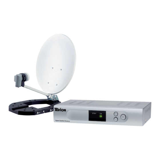
This operating manual will help you in the appropriate safe usage of the digital mini satellite system, hereafter called the “satellite system” in short. The satellite system is packed in a soft carry bag and consists of: a digital satellite receiver (receiver unit), hereafter called the receiver in short and the antenna unit with installation material. -
Page 6: Table Of Contents
Contents Overview of equipment ..............2 Remote control .................4 Preface....................5 Style features ..................5 Contents ....................6 Safety instructions ................8 Basic safety instructions............8 Appropriate use ................11 Contents ..................13 Description ..................14 Quick guide ..................17 Antenna installation ...............18 Installation of the antenna .............18 Installation options.................21 Receiver connection...............30... - Page 7 Screen-inlays while switching channels ........47 User interface on the TV screen............49 Menu structure................49 Menu structure................50 Menu navigation ................51 Channel (symbol: TV)..............52 Installation (symbol: Satellite antenna)........57 System Setup (symbol: gearwheel) ..........61 Tools (symbol: tools) ..............65 Software update via satellite ............66 Keys with special functions ............67 Switch between TV and SAT ............67...
-
Page 8: Safety Instructions
Safety instructions Please read the safety instructions carefully before operating the satellite system . Please follow all warnings and instructions on the equipment and in the operating manual. Basic safety instructions Electrical connection Do not expose the receiver to rain or any kind of humidity to avoid risk of fire and electric shock. - Page 9 If a cable used for the mains supply is damaged, the receiver must be repaired by an expert before reusing it. Otherwise, there is a risk of electric shock. Never allow children to operate the receiver or to play with the antenna unit unless supervised.
- Page 10 Correct battery handling Batteries may contain toxic agents. Ensure that batteries are not within the reach of children. Children may eat and swallow batteries. Batteries that are discharged may damage the remote control. If the receiver is not in use for a long period of time, remove the batteries from the remote control.
-
Page 11: Appropriate Use
Appropriate use The satellite system receives digital satellite channels for private use. It is exclusively meant for this purpose and must only be used for the same. This also includes paying attention to all information contained in these operating instructions, especially the safety instructions. Due to its user-friendly installation and disassembly, the satellite system is ideal for mobile use (camping or caravans). - Page 12 Caution! The maximum bending moment of the satellite system is 15.30 Nm. Please make sure during installation that the fixation is able to withstand this pressure. Do not install the satellite system In places with difficult access. Mount the satellite system only in places where it will be easily accessible to you without any danger.
-
Page 13: Contents
Contents Check the product contents after your purchase. The receiver, the remote control, the 2 batteries, the external power pack and the 12V cable for the cigarette lighter are included in a box. We recommend packing these pieces again in the box when dismounting the system. -
Page 14: Description
Description You can receive uncoded (free-to-air) digital satellite channels with the satellite system without depending on a fixed mounted satellite antenna. The mobile antenna allows you to receive signals at different places, e.g. on a camping site. With the mounting parts, the antenna can be installed e.g. - Page 15 All receiver settings can be easily undertaken using the user interface (menu) on the TV screen. The multilingual user interface supports following languages: German Italian Spanish Greek English Polish Czech Slovak Hungarian Danish French Swedish Croatian Further features: Software update via satellite ASTRA 19° East or via the RS232 connection on the rear side of the device.
- Page 16 4,500 channel-storage locations Parental lock (preset password: 0000) 1 favourite list and 8 channel groups Automatic scan of broadcasting stations List editor for broadcasting stations Analogue sound output through Cinch connector (stereo), volume adjustment possible via remote control Coaxial digital output (digital audio) 2 Euro-SCART connections for TV and video set Video output signal CVBS Loop-through-function in standby mode for the connection of an...
-
Page 17: Quick Guide
Quick guide You must install, connect and adjust your satellite system in the following sequence to be able to use it. Install the antenna. Connect the receiver to the equipment. Install the LNB cable. Connect the LNB cable to the antenna. Direct the antenna roughly. -
Page 18: Antenna Installation
Antenna installation The antenna consists of a few individual components and is simple to install. Take out the system components from the transport bag. Remove the packing material. Installation of the antenna Step 1: Place the antenna with its base on a suitable surface and open it in the direction of the arrow until it is in a vertical position. - Page 19 Step 3: Now take the LNB arm down in direction of the arrow until it is locked in place. Step 4a: For installing of the LNB in the LNB bracket untighten the 2 screws of the LNB bracket and remove the top half of the LNB bracket.
- Page 20 Step 4b: Insert the LNB bracket in direction of the arrow as far as it will go into the LNB arm until the LNB bracket is locked. While you are doing this, press the clip with the button for installation slightly down. Press button to remove.
-
Page 21: Installation Options
Installation options The antenna can be set up in different ways using the installation material provided. For clarification, the installation options are illustrated in the pictures below.. To make the picture less complex the antenna cable is not illustrated here. For a complete installation of the satellite system the cable must be fixed at the LNB. - Page 22 Installation on a table Place the installed antenna on a table. The base of the antenna must be entirely placed on the table surface. After the cabling of the satellite system the antenna can be directed to the desired satellite. For this, please proceed as described in the section "Direction of the antenna"...
- Page 23 Installation on a mast First of all, rotate the antenna by 180° so that the LNB will face away from the antenna base. Now, flap down the antenna base by 90° using the articulation. Then fix the lateral rods with the wing nuts at the left and right side of the base to get the required stability.
- Page 24 After the cabling of the satellite system the antenna can be directed to the desired satellite. For this, please proceed as described in the section "Direction of the antenna" on page 37. For achieving a safe installation on the mast, please make sure that the plain washers are always placed between the wing nuts of the U bracket and the base.
- Page 25 Installation on a wall For this installation, you need four screws and four washers. These pieces are not included in the contents. First of all, rotate the antenna by 180° so that the LNB will face away from the antenna base. Now, flap down the antenna base by 90°...
- Page 26 Drill the four boreholes. The size of the bore holes must correspond to the dowels which are used. Countersink the four steel dowels into the boreholes. Put the base on the place of its installation and fasten it with the four screws.
- Page 27 Installation on lawns Place the installed antenna on the lawn. You can fix the base of the antenna e.g. with tent pegs (see arrows) on the lawn to protect it against external influences (such as wind, displacement or tipping over). After the cabling of the satellite system the antenna can be directed to the desired satellite.
- Page 28 Installation on a crate First of all, rotate the antenna by 180° so that the LNB will face away from the antenna base. Now, flap down the antenna base by 90° using the articulation. Then fix the lateral rods with the wing nuts at the left and right side of the base to get the required stability.
- Page 29 To achieve a higher stability, the bottles in the crate should be filled. For achieving a safe installation, please make sure that the plain washers are always placed between the wing nuts of the U bracket and the base. Helpline No. UK/Northern Ireland 01422 263270 Helpline No.
-
Page 30: Receiver Connection
Receiver connection The receiver is connected with your satellite antenna by means of a coaxial cable. If necessary, you will have to prepare a coaxial cable before connecting the receiver. Caution! Connect the receiver to the mains supply only after you have connected it to all equipment and the antenna properly. -
Page 31: Lnb Cable Installation
LNB cable installation (Cp. the installation diagram on the next page) For the installation of the F connectors on the coaxial cable you will need a knife (ideally a wire stripper) and side cutting pliers. When stripping the isolation, neither the inner core or the foil nor the wire netting must be damaged. - Page 32 Installation diagram Fasten the F connector of the coaxial cable onto the “LNB IN” antenna connection of the receiver. Fasten the other end of the coaxial cable on the LNB. Helpline No. UK/Northern Ireland 01422 263270 Rep. Ireland 1890 812049...
-
Page 33: Connection With The Scart Cable
Connection with the Scart cable Insert the Scart cable in the Scart socket “TV” on the receiver. Connect the Scart cable to the TV set. Follow the operating manual of the TV set. Insert the Scart cable in the Scart socket “VCR” of the receiver if you want to connect a video set. - Page 34 Connection diagram Helpline No. UK/Northern Ireland 01422 263270 Rep. Ireland 1890 812049...
-
Page 35: Connection With The Cinch Cable
Connection with the Cinch cable Connect the Cinch connectors of the Cinch cable to the “AUDIO R” and “AUDIO L” sockets of the receiver if you want to connect a stereo system. Caution! Never connect the Phono input of your stereo system to the receiver;... - Page 36 Connection of the coaxial digital output Insert the coaxial cable in the “COAXIAL” socket or the receiver. Connect the coaxial cable to the audio-digital receiver. Connection diagram The coaxial cable is not included in the scope of supply. Helpline No. UK/Northern Ireland 01422 263270 Rep.
-
Page 37: Direction Of The Antenna
Direction of the antenna Correct location The most common satellites are in southeastern direction, e.g. Astra 19,2° East, Eutelsat Hotbird 13° East, Astra2 28 East. The direction of the reception / antenna is determined by two angles: the horizontal azimuth angle = haa the vertical elevation angle = vea When searching the southern direction, the position of the sun might help you. - Page 38 Depending on which satellite you wish to receive, there must be free sight without any obstacles in this angle. This must be especially ensured with the installation on a wall. Please make sure that you are able to rotate your antenna in a manner that it does not touch the house wall.
-
Page 39: Rough Direction Of The Antenna
Rough direction of the antenna You must connect the LNB cable to LNB before directing the antenna. NOTE: For ease of alignment refer to APPENDIX 1 and the paper “compass” at the end of this manual. Caution! While connecting the LNB cable, the receiver must not be connected to the mains supply. - Page 40 Tighten the wing nuts as soon as the desired elevation is attained. Helpline No. UK/Northern Ireland 01422 263270 Rep. Ireland 1890 812049...
- Page 41 Elevation table Helpline No. UK/Northern Ireland 01422 263270 Helpline No. UK/Northern Ireland 01422 263270 Rep. Ireland 1890 812049 Rep. Ireland 1890 812049...
-
Page 42: Getting Started
Getting started Remote control Two Micro type batteries are required for the remote control: LR 03/AAA/1.5 V Open the battery compartment. Insert two batteries into the battery compartment paying attention to the indicated polarities and push the cover of the battery compartment carefully until it is locked. -
Page 43: Receiver
Receiver Caution! Check the proper connection of all devices and of the antenna before connecting the external power pack or the 12 V cable of the receiver to the power source and starting the receiver. Insert the mains plugs of the connected equipment in the mains socket and switch it on. -
Page 44: Fine Tuning Of The Antenna
Fine tuning of the antenna The reception quality set by you in the antenna settings may not be optimal. In this case, you must do a fine tuning of the antenna. The sat beeper supports you here. Please see the owner manual of the sat beeper for correct usage. - Page 45 When you have found a position with good reception quality, you must tighten the wing nuts again to fix the antenna . Slowly turn the antenna horizontally towards the right and subsequently towards the left. A digital satellite receiver receives the transmission signal of the satellite with a time lag.
- Page 46 Check the signal quality continuously. If you cannot find an antenna setting with good signal quality, adjust the antenna again in vertical direction by 1°. If you cannot find an antenna setting with good signal quality, adjust the antenna again in vertical direction by 1°. Find an antenna setting for attaining the best possible signal quality in this manner.
-
Page 47: Operation
Operation Screen-inlays while switching channels When a channel is switched, an information bar appears on the screen for 5 seconds. In this information bar, you will find the following indications: Channel name Received satellite Current date Current time (According to the presetting in menu item “Time“). - Page 48 Channel-group symbols Symbol Channel group Sport News Music Movie Shopping Education Leisure Should the current programme belong to the general channel group, no symbol will appear. Helpline No. UK/Northern Ireland 01422 263270 Rep. Ireland 1890 812049...
-
Page 49: User Interface On The Tv Screen
User interface on the TV screen You can make individual settings on your receiver using the menus in the user interface. For this purpose, both the receiver and the TV set need to be switched on and connected by a Scart cable. Press the “MENU”... -
Page 50: Menu Structure
Menu structure Main menu Sub-menu Description Channel TV Channel list See following text (symbol: Radio Channel list See following text Delete all See following text page: 52 Installation Antenna Setup See following text (symbol: Automatic Scan See following text Satellite TP Scan See following text antenna) -
Page 51: Menu Navigation
Menu navigation Use the keys “CH ”, “CH ”, “V+”, and “V-” to navigate within the menus. The selected menu items are marked. Confirm your selection with the “OK” key. By pressing the “EXIT” key you can exit the menu again. -
Page 52: Channel (Symbol: Tv)
Channel (symbol: TV) Sub-menu Description TV Channel list 1 Favorite, 2 Move, 3 Find, 4 Sort, 5 Edit, 6 Type, Select, V- V+ Group, OK Enter, EXIT Exit. Radio Channel as indicated above list Delete all Deletion of the complete channel list. For this purpose: Enter password (factory setting 0000) and confirm warning message with Yes. - Page 53 5 Edit This option is not available in the favourite list or a channel group. After entering the password (factory setting 0000), new selection options will appear. Sub-menu Description Edit 1 Delete, 2 Skip, 3 Lock, 4 Edit, 5 Create, 6 Del all, Select, V- V+ Group, P+P- Page, EXIT Exit.
- Page 54 4 Edit By pressing the 4 key, an editing menu will be displayed. Here, you can change the individual parameters as desired. Option Description Name Changes the name of the currently selected channel. By pressing the OK key, an editing mask will be displayed.
- Page 55 5 Create By pressing the 5 key, the create menu will be displayed. Here, a new channel can be created. Option Description Satellite Satellite selection (example: Astra1 19° East) TP Index Selection of the created transponder on the selected satellite. TP Frequency Data corresponding to the selection of the created transponder.
- Page 56 To exit with saving changes select save and confirm by Save pressing the OK key. To exit without saving changes select cancel and Exit confirm by pressing the OK key. 6 Del(ete) all Via the 6 key you can mark all channels to be deleted. Thereafter, individual channels can be deselected again by pressing the 1 key.
-
Page 57: Installation (Symbol: Satellite Antenna)
Installation (symbol: Satellite antenna) Sub-menu Description Antenna setup Satellite Satellite selection (example: Astra1 19° East) LNB type Select LNB type (default setting is Universal) 22KHz activation (Note: with the LNB type Universal activation occurs automatically) DiSEqC Select DiSEqC level DiSEqC switch Select DiSEqC command Example: Astra and Hotbird double reception... - Page 58 channels Free = only unencrypted channels Scan Channel Selection between TV and radio or only TV or only radio Search Start scan by pressing the OK key. The channels found are added. TP Scan (manual With this scanning function, you can scan the preset channel scan) frequencies (transponders) individually.
- Page 59 Free = only unencrypted channels Scan Channel Selection between TV and radio or only TV or only radio Search Start scan by pressing the OK key. Helpline No. UK/Northern Ireland 01422 263270 Helpline No. UK/Northern Ireland 01422 263270 Rep. Ireland 1890 812049 Rep.
- Page 60 Table for the TP Index Sub-menu Description Create new frequency (transponder): Menu item TP: Frequency: set desired frequency Menu item Polarity: set desired polarity The new frequency (transponder) is created after execution. When exiting the menu confirm the safety message by pressing the OK key. Only after confirmation the new frequency will be created.
-
Page 61: System Setup (Symbol: Gearwheel)
System Setup (symbol: gearwheel) Sub-menu Description Language Language Selection of menu language (OSD) First Audio Preselection of the audio language (if offered by the broadcasting station) Second Audio Preselection of the audio language (if offered by the broadcasting station) TV System Display Mode Selection of the transmission system;... - Page 62 OSD Setting Menu Style Setting of menu colour Subtitle Display Enabling of subtitles OSD Timeout Menu inlay time (OSD timeout) Menu transparency Transparency Load Default The default OSD setting can be OSD Setting restored The default password is 0000 Parental Lock Menu Lock Disabling of password input in the Installation menu...
- Page 63 Table for time setting Sub-menu Description GMT Usage Enable / disable GMT Offset Setting of the location-dependant divergence to Greenwich Mean Time Date Enabled if sub-menu “GMT Usage“ is disabled: Time input with the 0-9 keys of the remote control Time Enabled if sub-menu “GMT Usage“...
- Page 64 Table for timer setting Sub-menu Description Timer Number Selection of timer number 1-8. Timer Mode Repetition (once, daily, weekly, monthly, yearly, off). With the setting “Off“, the timer will be disabled. Timer Service Switching between programme timer (channel) and reminding function (message). Wakeup Channel With the timer service setting “Message“.
-
Page 65: Tools (Symbol: Tools)
Tools (symbol: tools) Sub-menu Description Information Display of reception parameters. (This function can Enabling of the acoustic beeper via the 1 key. also be accessed directly via the "INFO" key.) Game Here, the three games Tetris, Snake and Othello are available. -
Page 66: Software Update Via Satellite
Software update via satellite The update has nothing to do with the storage of new TV channels. It is rather meant to update the system software of the receiver. Normally, the update is not required for a trouble-free operation of the receiver. You must direct your satellite system towards the satellite Astra1 19°... -
Page 67: Keys With Special Functions
Keys with special functions Switch between TV and SAT With the “TV/SAT” key you can switch between TV and satellite functions. (This function has to be provided by your TV set). Press the “TV/SAT” key until you have set the desired function. Switch between TV and radio With the “TV/Radio”... -
Page 68: Audio
AUDIO With the “AUDIO” key you can select the audio track if a broadcasting station offers multi-channel sound. Additionally, you can enable the Dolby Digital mode here. (For this purpose you will additionally need a Dolby Digital system. The connection is made on the rear of the device via the COAXIAL socket). -
Page 69: M/P
Using Fasttext functions The coloured keys on the remote control are meant for Fastext and are enabled after invoking another Teletext page. These functions will be available for some channels only. You can get access directly to specific content by pressing the small coloured keys on the remote control that match the content on the screen. -
Page 70: Recall
Press the “FAV“ key to switch between the favorite list and the channel groups. Select with the V- and V+ keys. To exit the favorite list or the channel group, press the 1 key. RECALL By pressing the “RECALL” key, you will return to the previously selected channel. -
Page 71: Dismantling The Satellite System
Dismantling the satellite system Separate the receiver and the connected equipment from the power supply. Unscrew the LNB cable from the receiver and the LNB. Take the batteries out of the remote control, if you will not use the receiver for a longer period of time. Dismantle the antenna unit. -
Page 72: Cleaning
Cleaning Caution! The receiver must not become wet. Never clean it with a wet cloth. Do not use any cleaning agent containing solvents like petrol or thinners for cleaning. These agents may damage the surface of the casing. Clean the casing of the receiver with a dry cloth. Clean the antenna and mounting components with a slightly dampened cloth and mild soap sud. -
Page 73: Tips And Tricks/Trouble Shooting
Tips and tricks/Trouble shooting Symptom Possible cause and remedy Satellite cannot be Example: Astra1 19° East found, or no signal 1 Key (preset: “ARD“) “INFO“ key (“ARD“, FR11837) Signal AND quality are both at 0% Direct vertical reflector towards south Turn some millimetres to the left, wait approx. - Page 74 Poor image, blocking The antenna is not directed precisely towards the error, formation of satellite. small blocks, sound Direct the antenna more precisely. For this purpose, use stops the “Info” key of the remote control. The signal strength will be displayed for directing the antenna properly. The LNB is defective.
- Page 75 Cannot remember Please contact the service hotline if you have forgotten personal password your personal password. Default value The factory settings are restored if you keep the standby key at the face of your receiver pressed for more than 10 seconds. Caution! By doing this, your personal settings will be deleted.
-
Page 76: Disposal
Disposal Never throw the digital mini satellite system in normal household waste. Ask your municipal authorities or local government about different methods for disposing of the equipment in an eco-friendly and proper manner. Never throw the batteries into normal household waste. Batteries may contain toxic agents. -
Page 77: Specifications
Specifications Receiver Dimensions in mm (W × D × H) 210 × 145 × 45 Weight in grammes Receiver 553 g Remote control 80 g (without batteries) Input frequency range 950 MHz ~ 2'150 MHz IF band width 55 MHz / 8 MHz (below 5MS/s) LNB power 13V/18V GS, 0.30 A max. - Page 78 Power supply Power pack input voltage 100-240 V ~, 50/60 Hz Power pack output voltage 12 V , 1.0 A Weight power pack in grammes 108 g Receiver input voltage 11 – 14 V Power consumption receiver approx. 12 W (operation with Single LNB) approx.
-
Page 79: Declaration Of Conformity
Guideline on electromagnetic compatibility, 89/336/EEC EN 55 013 EN 55 020 EN 61000-3-2 EN 61000-3-3 Equipment type/model: Digital Mini Satellite System Helpline No. UK/Northern Ireland 01422 263270 Helpline No. UK/Northern Ireland 01422 263270 Rep. Ireland 1890 812049 Rep. Ireland 1890 812049... -
Page 80: Glossary
Glossary Alternating Current connection for alternating current Direct Current connection for direct current Cinch Coaxial connector for connecting the TV set or stereo connector system. DiSEqC Digital Satellite Equipment Control Digital system, with which the receiver can control different components of the external unit. It is especially used for selecting from multiple satellite positions (for example Astra and Eutelsat). - Page 81 Abbreviation for Video Cassette Recorder. This product must be disposed of correctly. Please contact your Local Authority for the appropriate method of disposal. Helpline No. UK/Northern Ireland 01422 263270 Helpline No. UK/Northern Ireland 01422 263270 Rep. Ireland 1890 812049 Rep. Ireland 1890 812049...
- Page 82 APPENDIX I PORTABLE SATELLITE TV SYSTEM Portable Satellite Dish Alignment Instructions & Information Satellites are located every 3 degrees in a geostationary orbit 35,000 kilometres above the earths surface at the equator which is known as the Clarke Belt. No matter where you are on the earths surface the satellites will always be located at the same position the only thing that changes is the elevation as you move further north or south.
-
Page 83: Fine Tuning
Using the blue keys on the remote select the right key until the highlighted indicator is on the geared cog symbol. Language selection should be set to English. Exit menu. Press List Select Astra 28 east by pressing the LEFT or RIGHT buttons Select BBC1 London (Highlight in Yellow) Press OK... - Page 84 1 Turn the dish on the horizontal plane towards the east (left as viewed from behind), 2 or 3 degs at a time and then wait to hear the audible signal indicator change, wait for two or three seconds, adjust 2 or 3 degs and wait again, after the second or third adjustment you should hear a change in the sound level, its a good idea to have a friend relaying the signal intensity and quality reading during this stage.
- Page 85 so for the south of England elevation is about 5 degrees and for the north of Scotland the elevation needs to be minus i.e. the dish needs to be leaning forward 2-3 degrees. NOTE: You can also use the included “Satellite Bleeper” to assist in fine tuning the position of the dish.
- Page 87 DIGITAL MINI SATELLITE SYSTEM WARRANT Y CARD Congratulations! You have made an excellent choice with the purchase of this quality product. Our commitment to quality also includes our service. Should you, contrary to expectations, experience defects due to manufacturing faults during private use within 36 months of the date of purchase we shall be liable for warranty in accordance with statutory warranty regulations provided that: - the device was not put to any use other than the intended...
- Page 88 DIGITAL MINI SATELLITE RECEIVER SYSTEM FAULT REPORT CARD In order to deal with your enquiry as quickly and efficiently as possible please contact the below helpline numbers: Helpline Numbers: UK 01422 263270 ROI 1890 812 049 KEY ELECTRONICS UNIT 20, ENTERPRISE CITY MEADOWFIELD AVENUE SPENNYMORE COUNTY DURHAM...
Need help?
Do you have a question about the DIGITAL MINI SATELLITE SYSTEM and is the answer not in the manual?
Questions and answers