Table of Contents
Advertisement
Advertisement
Table of Contents

Summary of Contents for Exerpeutic Inversion Table
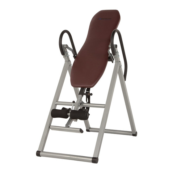
- Page 1 Inversion Table OWNER’S Item #5503 MANUAL...
-
Page 2: Table Of Contents
TABLE OF CONTENTS SERVICE ------------------------------------------------------------------------- 2 IMPORTANT LABELS -------------------------------------------------------- 3 IMPORTANT SAFETY INSTRUCTIONS -------------------------------- 4 PART DRAWING --------------------------------------------------------------- 5 PART LIST ----------------------------------------------------------------------- 6 INCLUDED HARDWARE & TOOLS -------------------------------------- 7 ASSEMBLY ---------------------------------------------------------------------- 8 OPERATION AND ADJUSTMENTS --------------------------------------- 15 STORAGE ----------------------------------------------------------------------- 20 WARM UP ----------------------------------------------------------------------- 21 WARRANTY -------------------------------------------------------------------- 22 FAX FORM ---------------------------------------------------------------------- 23... -
Page 3: Service
SERVICE IMPORTANT: FOR NORTH AMERICA ONLY To request product service and order replacement parts, please call our customer service department at: 1-866-924-1688 Monday through Friday, 8:00 AM-5:00 PM Pacific Standard Time, service@paradigmhw.com or email us at: Please visit our website at www.paradigmhw.com. Please have the following information ready when requesting for service: Your name Phone number... -
Page 4: Important Labels
IMPORTANT LABELS... -
Page 5: Important Safety Instructions
Do not operate this or any exercise equipment if it is damaged. Watch your body: come up slowly, dizziness after a session means you came up too fast. Wait a while after eating before using the inversion table. If you get nauseous, come up as soon as you feel queasy. -
Page 6: Part Drawing
PART DRAWING... -
Page 7: Part List
PART LIST Description Qty No. Description 001 Backrest (#5503) 1 026 Ring Pin Ø8x63.5mm 002 Backrest Frame 1 027 Hexagon Socket Head Cap Bolt M8x62mm 003 Adjustable Boom 1 028 Hexagon Socket Head Cap Bolt M8x20mm 004 Foot Bar 1 029 Plastic Washers 005 Adjustable Instep Frame 1 030 Foot Bar Oval End Cap 006 Handlebar... -
Page 8: Included Hardware & Tools
INCLUDED HARDWARE & TOOLS (19) Flat Washer (20) Hexagon Socket Head (24) Nut Cap M8 4 PCS Ø16xØ8.5x1.5 Cap Bolt M8x60mm 12 PCS 4 PCS (26) Ring Pin Ø8x63.5mm (28) Hexagon Socket Head (42) Nylon Nut M8 1 PC Cap Bolt M8x20mm 5 PCS 4 PCS (43) Flat Washer... -
Page 9: Assembly
ASSEMBLY Step 1: Stand up the base of the machine by separating the frames as shown above. Pull the Rear/Front Frames (8, 9) as far apart as possible from each others and align the pin holes. Then insert the Ø8x63.5mm Ring Pin (26) from inner side into the holes on the Rear/Front Frames (8, 9) to lock the frames in place. - Page 10 ASSEMBLY Tool: Allen Wrench #6 1 Wrench (#13 & #17) Step 2: Attach the Handlebar (6) onto the Rear Frame (8) with two M8x60mm Hexagon Socket Head Cap Bolts (20), two M8 Nut Caps (24), and four Ø16xØ8.5x1.5 Flat Washers (19). Tighten bolts and nut caps with the Wrench and Allen Wrench provided.
- Page 11 ASSEMBLY Tool: Allen Wrench #6 1 Wrench (#13 & #17) Step 3: Mount the Backrest Frame (2) to the Pivot Arms (11) by inserting the ends of the Pivot Arms (11) into the brackets, located at each side of the Backrest Frame (2), align to the bolt holes on the Pivot Arms (11) and brackets.
- Page 12 ASSEMBLY Step 4: Pull up on the Adjustable Instep Frame Knob (40), slide the Adjustable Instep Frame (5) completely out of the Adjustable Boom (3) and then turn the Adjustable Instep Frame (5) with the adjustable holes facing up. Release the Adjustable Instep Frame Knob (40) and adjust the Adjustable Instep Frame (5) slightly until the Adjustable Instep Frame Knob (40) locks into place.
- Page 13 ASSEMBLY Tool: Slot 2 Wrenches (#13 & #17) Step 6: Slide the Rod (10) with both slots facing the Adjustable Instep Frame Knob (40) through the large round hole on the side of Adjustable Boom (3), and secure the Rod (10) on the Adjustable Boom (3) with one M8 Nylon Nut (42), one Ø16xØ8.5x2.0 Flat Washer (43), one Metal Bushing (44), and M8x48mm Hexagon Head Bolt (45).
- Page 14 ASSEMBLY Step 7: Slide one Front Heel Holder (13) onto one end of the Adjustable Instep Frame (5). Use the same procedure to attach the other Front Heel Holder (13) onto the other end of the Adjustable Instep Frame (5). Install two Adjustable Instep Frame Round End Caps (39) onto both ends of the Adjustable Instep Frame (5) and Front Heel Holders (13).
- Page 15 Step 10: Attach the Nylon and Loop Straps (23, 35) to the inversion table by hooking the end of the Nylon Strap (23) to the pre-assembled loop on the back of the Backrest Frame (2) as shown. Now hook the other end of Loop Strap (35) to...
-
Page 16: Operation And Adjustments
The Adjustable Boom (3) can be moved to a variety of different positions, in order to accommodate the height of the person on the inversion table. To adjust the Adjustable Boom (3) pull out the Adjustable Boom Knob (41), and slide the Adjustable Boom (3) up or down until the desired height on the height scale is positioned just below the Backrest Frame (2). - Page 17 NOTE: The inversion table should always return to the upright position when you move your hands below your waist. If it does not, the inversion table is probably not adjusted correctly to your height.
- Page 18 So, it is very important to make sure that the height is adjusted properly. To do this, mount the inversion table, lock your ankles into the heel holders, and lie back with your hands at your sides.
- Page 19 As you get more comfortable with the use, rock the backrest slowly by moving your arms up and down slowly. It is recommended that the inversion table be used for five or ten minutes each morning, and again each evening.
- Page 20 OPERATION AND ADJUSTMENTS SUGGESTIONS FOR USE 1. Begin slowly: invert only 15~20 degrees to begin with. Stay inverted only as long as you are comfortable. Return upright slowly. 2. Make gradual changes: increase the angle only if it is comfortable. Increase angle only a few degrees at a time.
-
Page 21: Storage
Frames (8, 9) together until they meet. Insert the Ring Pin (26) back into the hole on the Front Frame (9). Now the inversion table is ready to be stored, allowing you to unfold it quickly and easily whenever you want to use it. -
Page 22: Warm Up
WARM UP Quadriceps Stretch With one hand against a wall for balance, reach behind you and pull your right foot up. Bring your heel as close to your buttocks as possible. Hold for 15 counts and repeat with left foot up. Inner Thigh Stretch Sit with the soles of your feet together with your knees pointing outward. -
Page 23: Warranty
WARRANTY Paradigm Health & Wellness, Inc. warrants to the original purchaser that this product is free from defects in material and workmanship when used for the purpose intended, under the conditions that it has been installed and operated in according to Paradigm’s Owner’s Manual. -
Page 24: Fax Form
FAX FORM PARADIGM PARTS REQUEST FAX FORM Please fax this form to (1-626-810-2166) OR YOU CAN EMAIL CUSTOMER SERVICE REQUESTS TO service@paradigmhw.com NAME: _______________________________________________________ ADDRESS: ____________________________________________________ CITY ______________ STATE ______________ ZIP ___________________ TELEPHONE: (Day) _____________________________________________ (Night) ____________________________________________ (Email Address) ____________________________________ SERIAL#: __________________________________________ MODEL#: __________________________________________ PURCHASE DATE: ______________________________________________...
Need help?
Do you have a question about the Inversion Table and is the answer not in the manual?
Questions and answers