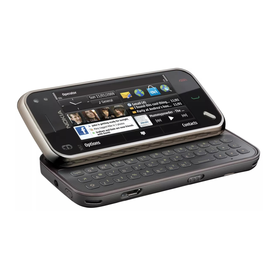
Nokia N97 mini Service Manual
Rm-553, rm-555
Hide thumbs
Also See for N97 mini:
- User manual (343 pages) ,
- Service schematics (12 pages) ,
- Specifications (1 page)
Table of Contents
Advertisement
Quick Links
1
SERVICE MANUAL
Level 1&2
RM-553 / RM-555
Transceiver characteristics
Band:
RM-555: WCDMA HSDPA 900/1900/2100 + 4-band GSM
RM-553: WCDMA HSDPA 850/1900/2100 + 4-band GSM
Display:
3.2" TFT, up to 16 million colours
nHD 16:9 widescreen aspect ratio, 640x360 pixel
resolution
Camera:
Main camera: 5.0 MPix CMOS, Dual LED Flash, Auto
focus
Secondary camera: 640x480 QVGA
Operating System:
Symbian OS ver. 9.4 Series60 5th Edition (5.0)
Connections:
WLAN IEEE 802.11 b/g with UPnP support, USB 2.0
(micro USB), Bluetooth 2.0 + EDR + A2DP, 3.5mm AV
connector
Talk time
GSM:
Up to 320 mins
WCDMA:
Up to 256 mins
Note: Talk times are dependant on network
parameter settings.
Confidential Copyright © 2009 NOKIA All rights reserved
Nokia N97 mini
RM-553 / RM-555
Service Manual Level 1&2
Standby
GSM:
Up to 342 hrs
WCDMA:
Up to 315 hrs
Version 1.0
ISSUE 1
Advertisement
Table of Contents

Related Manuals for Nokia N97 mini


Summary of Contents for Nokia N97 mini
- Page 1 Up to 320 mins Up to 342 hrs WCDMA: WCDMA: Up to 256 mins Up to 315 hrs Note: Talk times are dependant on network parameter settings. Confidential Copyright © 2009 NOKIA All rights reserved Version 1.0 ISSUE 1...
-
Page 2: Table Of Contents
Disassembly instructions ..............................12 11. Assembly hints ..................................19 12. Touch panel recalibration ..............................21 12.1 Recalibration setup ................................21 12.2 Recalibration procedure ..............................23 12.3 Troubleshooting ................................25 13. Solder Components ................................26 Confidential Copyright © 2009 NOKIA All rights reserved Version 1.0 ISSUE 1... -
Page 3: Change History
31.08.2009 First approved version The purpose of this document is to help NOKIA service levels 1 and 2 workshop technicians to carry out service to NOKIA products. This Service Manual is to be used only by authorized NOKIA service suppliers, and the content of it is confidential. Please note that NOKIA provides also other guidance documents (e.g. -
Page 4: Copyright
Nokia operates a policy of continuous development. Nokia reserves the right to make changes and improvements to any of the products described in this document without prior notice. Under no circumstances shall Nokia be responsible for any loss of data or income or any special, incidental, consequential or indirect damages howsoever caused. -
Page 5: Warnings And Cautions
3. Use only approved components as specified in the parts list. 4. Ensure all components, modules screws and insulators are correctly re–fitted after servicing and alignment. 5. Ensure all cables and wires are repositioned correctly Confidential Copyright © 2009 NOKIA All rights reserved Version 1.0 ISSUE 1... -
Page 6: Esd Protection
RM-553 / RM-555 Service Manual Level 1&2 4. ESD PROTECTION Nokia requires that service points have sufficient ESD protection (against static electricity) when servicing the phone. Any product of which the covers are removed must be handled with ESD protection. The SIM card can be replaced without ESD protection if the product is otherwise ready for use. -
Page 7: Care And Maintenance
All of the above suggestions apply equally to the product, battery, charger or any accessory. Confidential Copyright © 2009 NOKIA All rights reserved Version 1.0 ISSUE 1... -
Page 8: Battery Information
Batteries’ performance is particularly limited in temperatures well below freezing. Do not dispose batteries in a fire! Dispose of batteries according to local regulations (e.g. recycling). Do not dispose as household waste. Confidential Copyright © 2009 NOKIA All rights reserved Version 1.0 ISSUE 1... -
Page 9: Exploded View
SCREW M1.4x3.6 TORX+ 4IP PANHEAD 2.5X0.6 TORX+ 4IP I0211 I0212 BATTERY COVER ASSY I0214 Only available as These parts can not be Ver. 1.0 assembly reused after removal Confidential Copyright © 2009 NOKIA All rights reserved Version 1.0 ISSUE 1... -
Page 10: Service Devices
Service Bulletin (SB-011) on NOKIA Online. Supplier or manufacturer contacts for tool re-order can be BL-4D Battery found in “Recommended service equipment” document on NOKIA Online. Confidential Copyright © 2009 NOKIA All rights reserved Version 1.0 ISSUE 1... -
Page 11: Sw-Update
To use the FLS-5 Flash Dongle, follow the user guide inside the sales package. Please check always for the latest version of flash software, wich is available on Nokia Online. Confidential Copyright © 2009 NOKIA All rights reserved Version 1.0... -
Page 12: Disassembly Instructions
5) Remove the SIM TRAY. 6) Unscrew the four TORX+ size 4 screws in the order shown. Do not use them again. Discard them. Confidential Copyright © 2009 NOKIA All rights reserved Version 1.0 ISSUE 1... - Page 13 11) Then release the clips around the volume key. 12) Carefully slide the phone open. Use the SRT-6 to release the remaining clips holding the B-COVER. Remember not to touch the engine board. Confidential Copyright © 2009 NOKIA All rights reserved Version 1.0 ISSUE 1...
- Page 14 17) Lift the AV FPC ASSY carefully up and pull it out. 18) Use the SS-93 to carefully release two clips holding the engine board. Confidential Copyright © 2009 NOKIA All rights reserved Version 1.0 ISSUE 1...
- Page 15 24) Detach one end of the READER FPC using the SS- connector. While opening the connector, be careful not to damage the connector! The READER FPC ASSY cannot be reused. Confidential Copyright © 2009 NOKIA All rights reserved Version 1.0 ISSUE 1...
- Page 16 30) Carefully lift up the assembly to gain access to SRT-6 as shown. the A-COVER ASSY connector. Use the SS-93 to open the connector. Be careful not to damage the connector or any nearby components! Confidential Copyright © 2009 NOKIA All rights reserved Version 1.0 ISSUE 1...
- Page 17 35) Use the SS-93 to unlock the locking mechanism 36) Remove the LCD adhesive with the SS-93. of the LCD connector. Then carefully remove the LCD. Discard the adhesive. It cannot be used again. Confidential Copyright © 2009 NOKIA All rights reserved Version 1.0 ISSUE 1...
- Page 18 Nokia N97 mini RM-553 / RM-555 Service Manual Level 1&2 37) Nokia N97 mini disassembly is now complete. -END OF DISASSEMBLY- Confidential Copyright © 2009 NOKIA All rights reserved Version 1.0 ISSUE 1...
-
Page 19: Assembly Hints
5) Tighten the two M1.4 x 5.8 P3642 screws to the 6) Tighten this M1.2X2, PANHEAD 2.5X0.6 T PLUS- torque of 12 Ncm in the order shown. 4IPscrew to the torque of 7 Ncm. Confidential Copyright © 2009 NOKIA All rights reserved Version 1.0 ISSUE 1... - Page 20 9) Insert the USIM CARD TRAY. 10) Make sure the battery cover is assembled correctly. First attach thehooks on the Camera/Volume key side. Then close the LOCK KEY side. Confidential Copyright © 2009 NOKIA All rights reserved Version 1.0 ISSUE 1...
-
Page 21: Touch Panel Recalibration
5. Start Phoenix Service SW. 6. Select USB connection. 7. Scan Product (Phoenix > File > Scan Product) 8. Put the phone into Local Mode Confidential Copyright © 2009 NOKIA All rights reserved Version 1.0 ISSUE 1... - Page 22 Nokia N97 mini RM-553 / RM-555 Service Manual Level 1&2 9. Open Testing > Touch Panel Recalibration 10. Start the calibration Confidential Copyright © 2009 NOKIA All rights reserved Version 1.0 ISSUE 1...
-
Page 23: Recalibration Procedure
1. Touch the center of the “+” points on the Phone UI in the correct order (1, 2, 3) using the SS-93 Tool. After touching each point on the phone UI, check that the touch was registered properly on the phoenix screen. Confidential Copyright © 2009 NOKIA All rights reserved Version 1.0 ISSUE 1... - Page 24 SS-93/stylus. Check also that lines can be drawn to the edges (within 1-2mm) of the screen. Confidential Copyright © 2009 NOKIA All rights reserved Version 1.0 ISSUE 1...
-
Page 25: Troubleshooting
There are large “dead” areas where lines cannot be drawn Restart Phoenix and retry the calibration again. If verification continues to fail, contact your next level of support. Confidential Copyright © 2009 NOKIA All rights reserved Version 1.0 ISSUE 1... -
Page 26: Solder Components
RM-553 / RM-555 Service Manual Level 1&2 13. SOLDER COMPONENTS X2100 X5400 X4401 X4400 X5200 V3374 F3300 S4404 G2200 BOTTOM X6001 X6002 X7401 X7403 X7402 Ver. 1.0 Confidential Copyright © 2009 NOKIA All rights reserved Version 1.0 ISSUE 1...