
Related Manuals for Husqvarna RIDE MOWER 2748 GLS (CA)


Summary of Contents for Husqvarna RIDE MOWER 2748 GLS (CA)
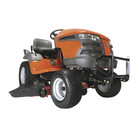
- Page 1 Operator's 2008-03 Manual O0802055 Ride Mower 2748 GLS (CA) 96043005000 03002 Operator's Manual...
-
Page 3: Safety Rules
Safe Operation Practices for Ride-On Mowers DANGER: THIS CUTTING MACHINE IS CAPABLE OF AMPUTATING HANDS AND FEET AND THROW ING OBJECTS. FAILURE TO OBSERVE THE FOLLOWING SAFETY INSTRUCTIONS COULD RESULT IN SERIOUS INJURY OR DEATH. WARNING: In order to prevent ac- ci den tal starting when setting up, trans port ing, ad just ing or making repairs, al ways dis con nect spark plug... - Page 4 Safe Operation Practices for Ride-On Mowers III. CHILDREN Tragic accidents can occur if the operator is not alert to the presence of children. Children are often attracted to the ma chine and the mowing activity. Never assume that children will remain where you last saw them. •...
-
Page 5: Table Of Contents
Gasoline Capacity 4 Gallons and type: Unleaded Regular Oil Type (API-SG-SL): SAE 30 (above 32°F) SAE 5W-30 (below 32°F) Oil Capacity: w/Filter: w/o Filter: 60 oz Spark Plug: Champion QC12YC (Gap: .040") Ground Speed (MPH): Forward: Reverse: Charging System: 16 AMPS Battery: AMP/HR: MIN. -
Page 6: Assembly
UNASSEMBLED PARTS (1) Oil Drain Tube Your new tractor has been assembled at the factory with exception of those parts left unassembled for shipping purposes. To ensure safe and proper operation of your tractor all parts and hardware you assemble must be tightened securely. Use the correct tools as necessary to insure proper tightness. -
Page 7: Assembly
NOTE: You may now roll or drive your tractor off the skid. Follow the ap pro pri ate instruction below to remove the tractor from the skid. WARNING: Before start ing, read, un der stand and fol low all in struc tions in the Op er a tion section of this man u al. Be sure tractor is in a well-ventilated area. -
Page 8: Operation
These symbols may appear on your tractor or in literature supplied with the product. Learn and understand their meaning. REVERSE NEUTRAL REVERSE ENGINE OFF OPERATION SYSTEM (ROS) LIGHTS ON BATTERY FUEL ATTACHMENT ATTACHMENT CLUTCH DISENGAGED CLUTCH ENGAGED FREE WHEEL (Automatic Models only) Failure to follow instructions could result in serious injury or death. - Page 9 KNOW YOUR TRACTOR READ THIS OWNER'S MANUAL AND SAFETY RULES BEFORE OPERATING YOUR TRACTOR Compare the illustrations with your tractor to familiarize yourself with the locations of various controls and ad just ments. Save this manual for future reference. Our tractors conform to the applicable safety standards of the American National Standards Institute. (A) ATTACHMENT LIFT LEVER –...
- Page 10 The operation of any tractor can result in foreign objects thrown into the eyes, which can result in severe eye dam age. Always wear safety glass es or eye shields while operating your tractor or per form ing any adjustments or repairs. We rec om mend a wide vision safety mask over spectacles or stan dard safety glasses.
- Page 11 TO MOVE FORWARD AND BACKWARD (See Fig. 7) The direction and speed of movement is controlled by the Motion Control Lever (J). FIG. 7 • Start tractor with motion control le ver in neutral (N) position. • Release parking brake. •...
-
Page 12: Before Starting The Engine
REVERSE OPERATION SYSTEM (ROS) Your tractor is equipped with a Reverse Operation System (ROS). Any attempt by the operator to travel in the reverse direction with the attachment clutch engaged will shut off the engine unless ignition key is placed in the ROS "ON" position. - Page 13 ADD GASOLINE • Fill fuel tank to bottom of filler neck. Do not overfill. Use fresh, clean, regular un lead ed gasoline with a minimum of 87 octane. (Use of leaded gasoline will increase carbon and lead oxide deposits and reduce valve life). Do not mix oil with gasoline.
-
Page 14: Operation
• Sitting in the tractor seat, start engine. After the engine is running, move throttle control to half (1/2) speed. Disengage parking brake. • Drive tractor forward for approximately five feet then backwards for five feet. Repeat this driving procedure three times. -
Page 15: Maintenance Schedule
MAINTENANCE SCHEDULE Check Brake Operation Check Tire Pressure Check Operator Presence & ROS Systems Check for Loose Fasteners Check/Replace Mower Blades Lubrication Chart Check Battery Level Clean Battery and Terminals Check Transaxle Cooling Check Mower Levelness Check V-Belts Check Engine Oil Level Change Engine Oil (with oil filter) Change Engine Oil (without oil filter) Clean Air Filter... -
Page 16: Maintenance
TRACTOR Always observe safety rules when per form ing any main- te nance. BRAKE OPERATION If tractor requires more than five (5) feet to stop at highest speed in high est gear on a level, dry concrete or paved surface, then brake must be serviced. (See “TO CHECK BRAKE”... -
Page 17: Clean Air Screen
• Rinse the battery with plain water and dry. • Clean terminals and battery cable ends with wire brush until bright. • Coat terminals with grease or petroleum jelly. • Reinstall battery (See “REPLACING BATTERY" in the SERVICE AND ADJUSTMENTS section of this man u al). -
Page 18: Spark Plugs
ENGINE OIL FILTER Replace the engine oil filter every season or every other oil change if the tractor is used more than 100 hours in one year. MUFFLER Inspect and replace corroded muffler and spark arrester (if equipped) as it could create a fire hazard and/or dam- age. -
Page 19: Service And Adjustments
SERVICE AND ADJUSTMENTS WARNING: TO AVOID SERIOUS INJURY, BEFORE PERFORMING ANY SER VICE OR AD JUST - MENTS: • Depress brake pedal fully and set parking brake. • Place attachment clutch in “DISENGAGED” position. • Turn ignition key to “STOP” and remove key. •... - Page 20 SERVICE AND ADJUSTMENTS • From right side of mower, disconnect anti-sway bar (S) from right rear mower bracket (D) - remove retainer spring and washer and pull mower toward you until the bar falls from the hole in bracket. • Turn tractor steering wheel to the left as far as it will go.
- Page 21 SERVICE AND ADJUSTMENTS • Repeat on opposite side of tractor. • ATTACH REAR LIFT LINKS (C) - Lift rear corner of mower and position slot in link assembly over pin on rear mower bracket (D) and secure with washer and retainer spring.
- Page 22 SERVICE AND ADJUSTMENTS TO LEVEL MOWER Make sure tires are properly inflated to the PSI shown on tires. If tires are over or under inflated, it may affect the appearance of your lawn and lead you to think the mower is not adjusted properly.
- Page 23 SERVICE AND ADJUSTMENTS Tighten adjust nut B to raise mower 02950 Loosen jam nut A first FIG. 28 NOTE: Each full turn of the adjustment nut will change mower height about 1/8". • Recheck measurements, adjust if necessary until front tip of blade is 1/8"...
-
Page 24: Front Wheel Toe-In/Cam Ber
SERVICE AND ADJUSTMENTS TO REPLACE MOTION DRIVE BELT (See Fig. 30) Park the tractor on level surface. En gage parking brake. For as sis tance, there is a belt installation guide decal on bottom side of left footrest. BELT REMOVAL - •... - Page 25 SERVICE AND ADJUSTMENTS WASH ERS RE TAIN ING RING AXLE COVER SQUARE KEY (REAR WHEEL ONLY) FIG. 31 TO START ENGINE WITH A WEAK BATTERY (See Fig. 32) WARNING: Lead-acid batteries gen- er ate ex plo sive gases. Keep sparks, flame and smoking ma te ri als away from bat ter ies.
- Page 26 SERVICE AND ADJUSTMENTS TO REPLACE HEADLIGHT BULB • Raise hood. • Pull bulb holder out of the hole in the backside of the grill. • Replace bulb in holder and push bulb holder securely back into the hole in the backside of the grill. •...
-
Page 27: Storage
Immediately prepare your tractor for storage at the end of the season or if the tractor will not be used for 30 days or more. WARNING: Never store the trac tor with gas o line in the tank inside a building where fumes may reach an open flame or spark. -
Page 28: Trou Ble Shoot Ing
TROUBLESHOOTING POINTS PROBLEM CAUSE Will not start Out of fuel. Engine not “CHOKED” properly. Engine flooded. Bad spark plug. Dirty air filter. Dirty fuel filter. Water in fuel. Loose or damaged wiring. Carburetor out of adjustment. Engine valves out of adjustment. Hard to start Dirty air filter. -
Page 29: Trou Ble Shoot Ing
TROUBLESHOOTING POINTS PROBLEM CAUSE Engine dies when Reverse operation system tractor is shifted (ROS) is not "ON" while into reverse mower or other attachment is engaged. Engine continues to run Faulty operator-safety presence control system. when operator leaves seat with attachment clutch engaged Poor cut - uneven Worn, bent or loose blade. -
Page 30: Repair Parts
SCHEMATIC SCH12 PTO SWITCH (MATING SIDE) IGNITION SWITCH POSITION CIRCUIT “MAKE” M+G+A1 B+A1 RUN/OVERRIDE B+A1 L+A2 START B + S + A1 BATTERY FUSE AMMETER (OPTIONAL) WHITE PTO SWITCH (DISENGAGED) WHITE BLACK BLACK BLACK BLACK BLACK IGNITION UNIT (OPTIONAL) HOUR BLUE METER FUEL... - Page 31 ELECTRICAL T07S With 12V Outlet Option With Service Minder Option...
- Page 32 ELECTRICAL PART DESCRIPTION 532 16 34-65 Battery 874 76 04-12 Bolt Hex Hd 1/4-20 unc x 3/4 532 18 64-91 Battery Box 532 17 61-38 Switch Interlock 532 18 37-59 Harness Socket Light 532 00 41-52 Bulb, Light #1156 532 40 02-53 Cable Battery 532 41 28-95 Cable Starter 532 17 51-58 Fuse 873 51 04-00 Nut Keps Hex 1/4-20 unc...
- Page 33 CHASSIS chassis-tex_57-gt-husq_r1...
- Page 34 CHASSIS PART DESCRIPTION 532 40 50-12 Logo Husq. 532 40 87-01 Dash 532 41 10-46 Hood 532 19 89-07 Lens LH 532 40 86-07 Grille 532 19 89-06 Lens RH 532 19 61-25 Plate Engine 817 06 05-12 Screw 5/16-18 x 3/4 532 40 18-25 Fender 873 68 05-00 Nut Crown Lock 5/16-18 532 19 43-14 Bracket Fender...
- Page 35 DRIVE drive-tex_K66_fender_1...
- Page 36 DRIVE PART DESCRIPTION 532 41 41-45 Transaxle, TuffTorq K66 532 00 70-70 532 19 98-37 Hub Asm. Wheel 532 14 00-80 Bolt Hub Wheel 819 13 13-16 Washer 13/32 x 13/16 x 16 Ga. 532 40 10-72 Spring, Brake 532 19 73-29 Rod Shift 532 14 08-45 Knob Deluxe 1/2-13 unc...
-
Page 37: Steering Assembly
STEERING ASSEMBLY steering-tex_4-husq PART DESCRIPTION 532 41 64-80 Wheel, Steering 532 19 59-68 Axle Asm., Front 532 40 30-89 Spindle Asm., LH 532 40 30-90 Spindle Asm., RH 532 12 49-31 Bearing, Race Thrust Harden 532 12 17-48 Washer 25/32 x 1-5/8 x 16 Ga. 812 00 00-29 Ring, Clip #T5304-75 532 12 12-32 Cap, Spindle 532 12 17-49 Washer 25/32 x 1-1/4 x 16 Ga. - Page 38 ENGINE engine-tex_bs-2cyl_2 PART DESCRIPTION - - - - - - Engine B&S Model No. 44Q777- 1039-B1 532 14 97-23 Muffler 532 19 43-20 Keeper Asm. Belt Engine 532 17 93-35 Clutch Electric 532 19 43-43 Pulley Engine 532 19 34-99 Tank Fuel 4.0 532 19 42-67 Cap Asm 532 17 83-85 Control Throttle 532 41 63-58 Screw #10 x 0.750 BOS Thread...
-
Page 39: Seat Assembly
SEAT ASSEMBLY seat-tex_6.5SL_3 PART DESCRIPTION 532 40 66-21 Seat 532 18 01-66 Bracket Pivot Fender 532 14 06-75 Strap, Asm Fender 873 80 06-00 Nut, Lock w/Ins. 3/8-16 unc 532 12 41-81 Spring, Seat Cprsn 532 17 18-77 Bolt 5/16-18 unc x 3/4 w/Sems 532 19 69-77 Pan, Seat 532 17 18-52 Bolt, Shoulder 5/16-18 PART... - Page 40 DECALS PART DESCRIPTION 532 41 16-58 Decal, Operator’s 532 41 82-77 Decal, Deck Airinduct 532 17 05-63 Decal, Warning 532 41 84-96 Decal, Eng. H.P . 532 19 87-85 Decal, Mower Sch. 532 14 50-05 Decal, Battery Dnge/Poi 532 41 82-15 Decal, Panel Side 532 18 09-41 Decal, Cust.
-
Page 41: Mower Deck
MOWER DECK 48_deck_tex_21... - Page 42 MOWER DECK PART DESCRIPTION 532 41 87-00 Deck Weldment Mower 532 19 72-48 Cover Mandrel LH 532 19 91-02 Cover Mandrel RH 532 17 43-65 Bolt 7/16 Asm. Blade 532 18 00-54 Blade High Lift 532 17 39-21 Blade Mulching 532 40 03-37 Rod Anti Sway 532 18 72-91 Shaft Asm.
-
Page 43: Mower Lift
MOWER LIFT lift-tex_3 PART DESCRIPTION 532 19 52-23 Shaft Asm., Lift 532 19 52-30 Lever Asm., Lift RH 532 41 15-55 Grip, Lever 532 19 63-14 Spring Torsion 532 19 42-09 Pin Cotter 7/16 Bow Tie Lock 532 19 53-04 Spring Lift Assist 819 19 19-12 Washer Clear Zinc PART 532 19 42-08 Pin Cotter 5/16 Bow Tie Lock... - Page 45 532 41 88-49 Rev 1 03-31-08 SBW/TH Printed in U.S.A.