
Related Manuals for Husqvarna PF 21


Summary of Contents for Husqvarna PF 21
- Page 1 Oper ator ′ s manual PR 17 PR 17 AWD PF 21 PF 21 AWD Please r ead the operator’s manual carefully and make sure you E E E E n n n n g g g g l l l l i i i i s s s s h h h h...
-
Page 2: Table Of Contents
Checking and adjusting the steering wires ... Adjusting the parking brake PR 17, PF 21 ... Adjusting the parking brake PR 17 AWD, PF 21 AWD . Checking and adjusting of throttle wire ... Checking and adjusting the choke wire ... -
Page 3: Ser Vice Journal
Pre-deliver y service 1 Charge the battery for 4 hours at max. 3 amp. 2 Fit the venting hose on the battery. 3 Fit steering wheel, seat and any optional equipment. 4 Check and adjust tyre pressure (60 Kpa, 0.6 bar, 9 PSI). -
Page 4: Intr Oduction
Dear Customer , Thank y ou for choosing a Husqvarna Rider. Husqvarna Riders are built to a unique design with a front-mounted cutting unit and a patented rear-wheel steering system. Riders are designed for maximum efficiency even in small or confined areas. The closely grouped controls and pedal-operated hydrostatic transmission also contribute to the performance of this machine. -
Page 5: Key To Symbols
Symbols These symbols are on the machine and in the instr uctions. WARNING! Careless or incorrect use can result in serious or fatal injury to the operator or others. Please read the operator’s manual carefully and make sure you understand the instructions before using the machine. - Page 6 KEY T O SYMBOLS Chec k the engine’s oil level Check transmission oil level Lift up the cutting unit Apply the parking brake. If the engine is cold, use the choke Release the parking brake before driving 6 – English...
-
Page 7: Wha T Is What
PF 21 AWD 17 Product and serial number plate 18 Fuel cap 19 Cover lock 20 Lever to disengage the drive, PR 17 and PF 21 Lever to disengage the driving rear axle, PR 17 AWD and PF 21 English – 7... -
Page 8: Safety Instr Uctions
SAFETY INSTR UCTIONS Saf ety instructions These instr uctions are for your safety. Read them carefully. Insure y our Rider • Check the insurance coverage for your new Rider. • Contact your insurance company. • You should have fully comprehensive insurance including: third party, fire, damage, theft and liability General use •... -
Page 9: Driving On Slopes
SAFETY INSTR UCTIONS • Never allow children or other persons not trained in the use of the machine to use or service it. Local laws may regulate the age of the user. W ARNING! You must use approved personal protective equipment whenever you use the machine. -
Page 10: Children
SAFETY INSTR UCTIONS • Follow the manufacturer’s recommendations regarding wheel weights or counterbalance weights to increase machine stability. IMPORTANT INFORMATION Wheel weights fitted on the rear wheels are recommended when driving on slopes for safer steering and improved manoeuvrability. Consult your dealer concerning the use of wheel weights if you are unsure. -
Page 11: Transport
SAFETY INSTRUCTIONS • Do not change the setting of governors and avoid running the engine at excessively high revs. If you run too fast, you risk damaging the machine components. • Never use the machine indoors or in spaces lacking proper ventilation. -
Page 12: Presentation
PF 21 AWD. The machines are equipped with a four-stroke V- Twin engine from Kawasaki. The machines are equipped with power steering and hydraulic lifts. PR 17 AWD and PF 21 AWD also have all wheel drive. The power transmission from the engine is handled by a hydrostatic gearbox, which allows variable variation of the speed by using the pedals. -
Page 13: Cutting Unit
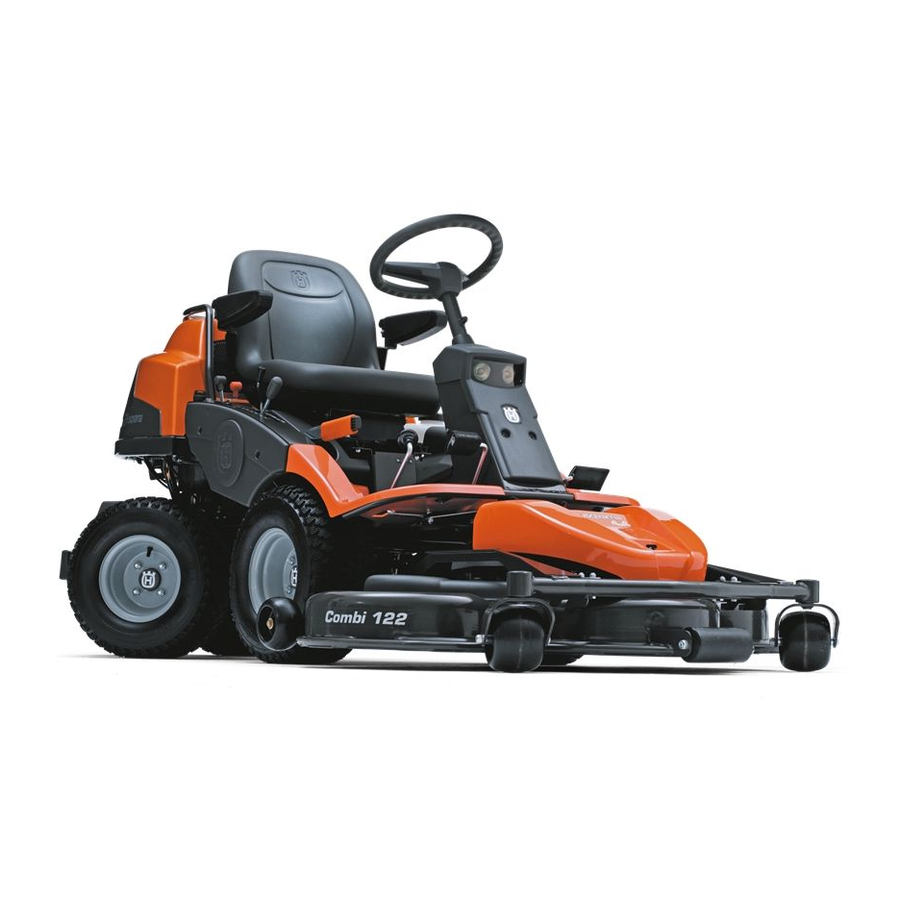
PR 17 and PR 17 AWD can be equipped with three different cutting units. Combi 94, Combi 103, Combi 112 PF 21 and PF 21 AWD can be equipped with two different cutting units. Combi 112 and Combi 122 The Combi-unit, equipped with a BioClip-plug, finely chops the cuttings to fertiliser. -
Page 14: Cutting Height Adjustment Lever
Do not use the fuel tank as a support area. Lights and power outlet PR 17 and PR 17 AWD PF 21 and PF 21 AWD The lights are switched on and off using the power switch (1) on the control panel. -
Page 15: Release Lever
Clutch control PR 17 AWD and PF 21 AWD PR 17 AWD and PF 21 AWD have one control for the front axle and one control for the rear axle. IMPORTANT! Always drive the machine with both clutch controls pressed in. -
Page 16: Driving
Start the engine 1 Make sure that the clutch control is depressed. PR 17 AWD and PF 21 AWD have one control for the front axle and one control for the rear axle. 2 Lift up the cutting unit by pulling the lever backwards to locked position (transport position) and apply the parking brake. -
Page 17: Starting The Engine With A Weak Battery
4 If the engine is cold move the choke lever backwards to its end position. 5 Turn the ignition key to the start position. 6 When the engine starts release the ignition key immediately back to neutral position. IMPORTANT INFORMATION Do not run the starter for more than about 5 seconds at a time. -
Page 18: Remove The Cables In The Reverse Order
Remove the cables in the reverse order • The BLACK cable is removed from the chassis and then the fully charged battery. • Finally the RED cable from both batteries. Driving the Rider 1 Release the parking brake by first pressing down the parking brake pedal and then releasing it. - Page 19 2 Move the throttle control to the MIN. position. Turn the ignition key to the ”STOP”. 3 When the Rider is at a standstill, press down the parking brake and push in the locking button. Driving – 19 English...
-
Page 20: Maintenance
Maintenance schedule The following is a list of the maintenance which should be conducted on the machine. For those points not described in this manual, visit an authorised service workshop. Maintenance Cleaning Check the engine’s oil level Check the engine’s cooling air intake Check the fuel pump air filter Check the steering wires Check the level of the battery acid... - Page 21 Weekly maintenance maintenance before starting 4,5) needs If the machine is used daily it should be lubricated Only PR 17 AWD, PF 21 AWD first change after 8 hours At least Maintenance once a interval in hours year – 21...
-
Page 22: Cleaning
Cleaning Clean the machine directly after use. It is much easier to wash off grass cuttings before they dry. Oily dirt can be removed using a cold degreasing agent. Spray on a thin layer. Rinse at normal water pressure. Do not direct the jet towards electrical components or bearings. -
Page 23: Checking And Adjusting The Steering Wires
WARNING! A poorly adjusted parking brake can result in reduced braking ability. Adjusting the parking brake PR 17 AWD, PF 21 AWD Check that the parking brake is adjusted correctly by placing the machine on a slope with the front and rear axles disengaged. -
Page 24: Checking And Adjusting Of Throttle Wire
3 Remove the left-hand wing cover. 4 Loosen the locking nuts. 5 Adjust the play between the casing and the adjustment screw to 1 mm (0.040") when one pulls the casing. This gives a play on the pedal of approximately 40 mm. 6 Tighten the nuts carefully to prevent damaging the adjuster screw. -
Page 25: Checking The Fuel Pump's Air Filter
Never brush the dirt away. Replace the air filter if it is very dirty. PF 21 and PF 21 AWD have an additional filter located behind the filter cartridge. Clean the filter by knocking it with care against a hard surface. Do not use compressed air for this filter. -
Page 26: Ignition System
Ignition system The engine is equipped with an electronic ignition system. Only the spark plug requires maintenance. For recommended spark plug, see Technical data. IMPORTANT INFORMATION Fitting the wrong spark plug type can damage the engine. Replacing the spark plug 1 Remove the ignition cable shoe and clean around the spark plug. -
Page 27: Check The Safety System
Check the safety system The machine is equipped with a safety system that prevents starting or driving under the following conditions. The engine should only be possible to start when the cutting unit is in its raised position and the parking brake is applied. The driver does not need to be seated in the driver’s seat. -
Page 28: Replacing The Light Bulbs
Replacing the light bulbs For information about the bulb type, see Technical Data. 1 Unscrew the two screws holding the cover on the power servo housing. 2 Lift up the cover and turn it around the steering shaft. 3 Unscrew the two screws holding the lamp insert. 4 Lift out the lamp insert. -
Page 29: Checking The Engine's Cooling Air Intake
Mind your fingers. Maintenance Replacing the rear drive belt PR 17 and PF 21 Removal 1 Lift up the cutting unit 2 Remove the transmission cover. 3 Unhook the spring (A) from the screw (B). -
Page 30: Replacing The Hydraulic Pump's Drive Belt Pr 17 Awd And Pf 21 Awd
Refit the spring (A). Replacing the hydraulic pump's drive belt PR 17 AWD and PF 21 AWD 1 Remove the transmission cover. 2 Unhook the spring on the belt tensioner 3 Remove the belt guide for the centre belt. -
Page 31: Replacing The Centre Belt
7 Fit the spring on the belt tensioner. Replacing the centre belt Remove the hose holder in the middle (PR 17 and PF 21) and the rear belt guide for the centre belt (all machine types). Remove the centre belt and mount a new belt. -
Page 32: Replacing The Front Belt
2 PF 21 and PF 21 AWD If PF 21 or PF 21 AWD is to be used with an accessory or with the cutting unit CombiTurf 112, the belt should be pulled on the outside of the outer runner wheel, otherwise the belt will be too long. -
Page 33: Removing The Cutting Unit
7 Fit the drive belt around the drive wheels of the cutting unit. Hook up the height adjustment strut. 8 Secure the collet spring. Fit the front cover. Removing the cutting unit WARNING! Wear protective glasses when dismantling the cutting unit. The spring which tensions up the belt may break and cause personal injury. -
Page 34: Adjusting The Parallelism Of The Cutting Unit
Adjusting the parallelism of the cutting unit 1 Remove the front hood and right-hand fender. 2 Undo the nuts on the lift strut. 3 Screw out (extend) the stay to raise the rear edge of the cover. Screw in (shorten) the stay to lower the rear edge of the cover. -
Page 35: Service Position For The Cutting Unit
Service position for the cutting unit The cutting head can be placed in the service position to provide easy access for cleaning, repairs and servicing. In the service position the cutting unit is raised and locked in the vertical position. Placing in the service position 1 Position the machine on flat ground. -
Page 36: Checking The Blades
Checking the blades To achieve the best mowing results it is important that the blades are undamaged and well-sharpened. Check that the blades’ attachment screws are tight. IMPORTANT INFORMATION Replacing or sharpening the blades should be conducted by an authorised service workshop. -
Page 37: Lubrication
General Remove the ignition key to prevent unintentional movements during lubrication. When lubricating with an oilcan, it ought to be filled with engine oil. When lubricating with grease, unless otherwise stated, grease 503 98 96-01 or another chassis or ball bearing grease offering good corrosion protection shall be used. -
Page 38: Driver Seat
Driver seat Fold up the seat. Lubricate the lengthways adjustment runners with oilcan. Throttle and choke cables, lever bearings • Remove the right side cover on the lever housing (3 screws) and open the engine cover. • Lubricate the cables’ free ends with the oilcan, even those by the engine. -
Page 39: Replacing The Engine Oil
Replacing the engine oil Open the engine cover. The engine oil should be changed the first time after 8 hours running time. It should then be changed after every 100 hours of running time. When operating with a heavy load or at high ambient temperatures, replace every 50 hours. -
Page 40: Hydraulic Oil Filter Change
(one on each side) and lift off the transmission cover. • Check that there is oil in the transmission’s oil tank. PR 17, PF 21. Fill if necessary with engine oil SAE 10W/ 40 (class SF–CC). PR 17 AWD, PF 21 AWD. Fill if necessary with oil Synthetic 10W/50 •... -
Page 41: Troubleshooting Schedule
Troubleshooting schedule Problem Engine does not start Starter motor does not turn over the engine Engine does not run smoothly Engine seems to have no power Engine overheats Battery does not charge Machine vibrates Uneven mowing Procedure There is no fuel in the fuel tank Spark plug defective Faulty spark plug connections or interchanged cables Dirt in the carburettor or fuel line... -
Page 42: Electrical And Hydraulic Systems
ELECTRICAL AND HYDRAULIC SYSTEMS PR 17 and PR 17 AWD Numbers correspond to: 1 Microswitch, hydrostatic transmission 2 Microswitch, cutting unit 3 Microswitch, seat 4 Ignition lock 5 Counter 6 Start relay 42 – English 7 Engine connectors 8 Main fuse 15 A 9 Fuse 7.5 A 10 Switch for the power outlet 11 Power outlet... - Page 43 ELECTRICAL AND HYDRAULIC SYSTEMS PF 21 and PF 21 AWD Numbers correspond to: 1 Microswitch, hydrostatic transmission 2 Microswitch, cutting unit 3 Microswitch, seat 4 Ignition lock 5 Counter 6 Start relay 7 Engine connectors 8 Main fuse 15 A 9 Fuse 7.5 A...
-
Page 44: Wiring Diagram
ELECTRICAL AND HYDRAULIC SYSTEMS Wiring diagram 44 – English... -
Page 45: Hydraulic System
ELECTRICAL AND HYDRAULIC SYSTEMS Hydraulic System PF 21 AWD PR 17, PR 17 AWD, PF 21 Keep the hydraulic system clean. Bear in mind that: • Thoroughly clean before the top-up cap is opened or any connector loosened. • Use clean containers when topping up the oil. -
Page 46: Storage
Winter storage At the end of the season, or if the machine is going to stand idle for more than 30 days, it should immediately be made ready for storage. Fuel which is left to stand for long periods (30 days or more) can leave tacky deposits which can block the carburettor and interfere with the engine. -
Page 47: Technical Data
Dimensions Length without cutting unit, mm/ft Width without cutting unit, mm/ft Height, mm/ft Operating weight with cutting deck, kg/lb Wheel base, mm/ft Track width, front, mm/ft Track width, rear, mm/ft Tyre dimensions Air pressure, rear - front, kPa / bar / PSI Max. - Page 48 100-104 83-88 Tuff Torq K 66 SAE 10W/40 Combi 112 Combi 122 ) in conformity with EC directive 2000/14/EC. If the machine can be equipped with different PF 21 AWD 2080/6,82 900/2,89 1160/3,80 330/728 1000/3,29 713 / 2,3 710 / 2,3 18 x 7.5 x 8...
- Page 49 Technical data concerning the cutting unit Cutting unit Cutting width, mm/inch Cutting heights, 7 positions, mm/inch Blade length, mm/inch Width, mm Weight, kg/lb IMPORTANT INFORMATION When the service life of this product has been served and it is no longer used it should be returned to the dealer or to an applicable station for recycling.
-
Page 50: Ec-Declaration Of Conformity (Applies To Europe Only)
Husqvarna AB, SE-561 82 Huskvarna, Sweden, tel.: +46-36-146500, hereby declares that Husqvarna PR 17, PR 17 AWD, PF 21 and PF 21 AWD up until 2010’s serial numbers (the year is clearly stated in plain text on the rating plate with subsequent serial number), complies with the requirements of the COUNCIL’S DIRECTIVE:... - Page 52 Original instructions 1151089-26 ´®z+S(|¶6@¨ ´®z+S(|¶6@¨ 2010-03-22...
Need help?
Do you have a question about the PF 21 and is the answer not in the manual?
Questions and answers