Table of Contents
Advertisement
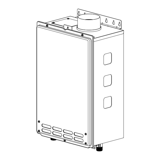
Hydro‐Smart 115
"Micro Boiler" for Radiant Heating
Installation Manual and Owner's Guide
Hydro‐Smart 115
Please make sure the proper gas pressure guidelines and recommendation from Hydro‐
Smart failure to do so can cause a fire or explosion and may result, causing property
damage, personal injury, or death.
ANSI Z21.10.3 and CSA 4.3
WARNING
property damage, personal injury or death.
‐Do not store or use gasoline or other
flammable vapors and liquids in the vicinity of
this or any other appliance.
‐WHAT TO DO IF YOU SMELL GAS
Do not try to light any appliance.
Do not touch any electric switch, do not
use any phone in your building.
Immediately call your gas supplier from a
neighbor's phone. Follow the gas
supplier's instructions.
If you cannot reach your gas supplier, call
the fire department.
‐Installation and service must be performed
by a qualified installer, service agency or the
gas supplier.
If you have any questions, please
call or write to:
Hydro‐Smart Inc.
10725 165th Ave NW,
Elk River, MN 55330
If the information in these
instructions is not followed
exactly, a fire or explosion
may result causing
Advertisement
Table of Contents

Related Manuals for Hydro-Smart 115


Summary of Contents for Hydro-Smart 115
- Page 1 Hydro‐Smart 115 “Micro Boiler” for Radiant Heating Installation Manual and Owner’s Guide ANSI Z21.10.3 and CSA 4.3 If the information in these instructions is not followed exactly, a fire or explosion WARNING may result causing property damage, personal injury or death. ‐Do not store or use gasoline or other flammable vapors and liquids in the vicinity of this or any other appliance. ‐WHAT TO DO IF YOU SMELL GAS Do not try to light any appliance. Do not touch any electric switch, do not ...
-
Page 2: Table Of Contents
Contents CONTENTS Installation Manual SPECIFICATIONS…………………………………………………………………………………………..………………………... 3 INTRODUCTION…………………………………………………………………………………………………..…………………. 4 SAFETY GUIDELINES…………….………………………………………………………………………………………..……….. 5 INSTALLATION………………………………………………………………………………………………..…………………..…. 6 General………………………………………………………………………………………………………………………..…..… 6 Clearances………………………………………………………………………………………………………………………….. 8 Included Accessories…………….………………………………………………………………………………………..….. 8 Optional Items……………………………………………………………………………………………………………………. 9 Warning for Installations……………………………………………………………………………………………………. High‐Altitude Installations………………………………………………………………………………………………….. Venting Instructions…………………………………………………………………………………………………………... Gas Supply and Gas Pipe Sizing……….................. Water Connections……………..……………………………………………………………………………………………… Electrical Connections……………………………………………………………………..…………………………….. Remote Controller Connections……..……………………………………………………………………….………..… APPLICATIONS...………………………………………………………………………………………………………………..…… INITIAL OPERATION..………………………………………………………………………………………………………….…… Owner’s Guide OPERATING SAFETY…………………………………………………………………………………………………………………... -
Page 3: Specifications
Specifications SPECIFICATIONS Hydro‐Smart 115 Model Natural Gas Input Min: 19,500 Btu/h (Operating Range) Max: 140,000 Btu/h Propane Input Min: 19,500 Btu/h (Operating Range) Max: 140,000 Btu/h Gas Connection ¾” NPT Water Connections ¾” NPT 15 ‐ 150 psi* Water Pressure Natural Gas Min. 5.0” WC Max. 10.5” WC Inlet Pressure Propane Min. 8.0” WC Inlet Pressure Max. 14.0” WC Natural 2.0” WC Manifold Pressure** Propane 2.5” WC Weight 33 lbs. Dimensions ... -
Page 4: Introduction
This manual provides information necessary for the installation, operation, and maintenance of the water heater. The model description is listed on the rating plate which is attached to the front panel of the water heater. Please read all installation instructions completely before installing this product. If you have any problems or questions regarding this equipment, consult with Hydro‐ Smart. Hydro‐Smart 115 is a water heater designed to be used with radiant heating in a combination Hydro Panel. Please read all installation instructions completely before installing this product. This product is only to be used with Hydro‐Smart Heating Panels, “Integrator”. The principle behind tankless water heaters is simple: Hydro‐Smart 115 ... -
Page 5: Safety Guidelines
Safety Guidelines SAFETY GUIDELINES SAFETY DEFINITIONS Indicates an imminently hazardous situation which, if not avoided, will result in death or serious injury. DANGER Indicates an imminently hazardous situation which, if not avoided, could result in death or serious injury. WARNING Indicates an imminently hazardous situation which, if not avoided, could result in minor or moderate injury. CAUTION GENERAL Follow all local codes, or in the absence of local codes, follow the most recent edition of the National Fuel Gas Code: ANSI Z223.1/NFPA 54 in the USA or CAN/CSA B149.1 Natural Gas, Propane Installation Code in Canada. Properly ground the unit in accordance with all local codes or in the absence of local codes, with the National Electrical Codes: ANSI/NFPA 70 in the USA or CSA standard C22.1 Canada Electrical ... -
Page 6: Installation
9. If you will be installing the water heater in a contaminated area with a high level of dust, sand, flour, aerosols or other contaminants/chemicals, they can become airborne and enter and build up within the fan and burner causing damage to the water heater. 10. For the Hydro‐Smart 115: These units may be converted to a direct‐vent (sealed combustion) appliance by installing a direct‐vent conversion kit Part No. 9007667005 (TK‐TV10) which will bring in all required combustible air from outside the building. When installing the direct‐vent conversion kit, please follow all instructions included with the kit. If the water heater is used as a direct‐vent appliance, the unit requires a 3” combustible air supply pipe. The intake pipe must be sealed airtight. Air supply pipe can be made of ABS, PVC, galvanized steel, corrugated aluminum, corrugated stainless steel or Category III ... - Page 7 Installation Installation and service must be performed by a qualified installer (for example, a licensed plumber or gas fitter), otherwise the warranty by Hydro‐ Smart will be void. WARNING The installer (licensed professional) is responsible for the correct installation of the water heater and for compliance with all national, state/provincial, and local codes. Hydro‐Smart does not recommend installing the water heater in a pit or location where gas and water can accumulate. ...
-
Page 8: Clearances
Back Side Side Front Bottom Model Top Bottom Front Back Sides Hydro‐Smart 115* 12” 12” 24” 1” 2 “ *Standard indoor installations and direct‐vent indoor installations have the same clearances. INCLUDED ACCESSORIES Check that these items below are included with the water heater. 1. Installation Manual and 2. Product Registration Card ... - Page 9 Installation 1. Backflow Preventer: 9007678005 (TK‐BF01) 2. Direct‐Vent Conversion Kit: 9007667005 The Backflow preventer prevents (TK‐TV10) the backflow of air through the This kit can be used to exhaust vent. This helps prevent convert the water harmful exhaust gases from heater from a standard entering the home, as well as vent system to a helping to prevent the unit from direct‐vent (or sealed freezing in areas where cold air can be blown combustion) system. or drawn into the exhaust system. Install this Install this conversion kit in accordance with vent damper in accordance with the the installation instructions and any applicable installation instructions and any applicable codes. codes. 3. Pipe Covers: 9007671005 (TK‐PCJr2) The pipe cover protects the plumbing pipes to the water heater from unexpected adjustments. This pipe cover is fixed to the bottom of the water heater, which hides the plumbing and improves the visual aspects of the whole installation for the water heater. 4. T‐Vent Wall Thimble with Termination: 9007608005 (TK‐KPWL4) and 9007609005 (TK‐KPWH4) These terminations are used when venting out through the wall and are compatible with the T‐Vent pipe system. These terminations are special stainless steel vents for gas appliances and are UL listed as Category II, III and IV. There are two types of terminations: the Louver termination and the Hood termination. For different wall thicknesses, there are two ranges Louver Hood ...
-
Page 10: Warning For Installations
Installation WARNING FOR INSTALLATIONS FOR YOUR SAFETY, READ BEFORE INSTALLATION: FOR YOUR SAFETY, READ BEFORE INSTALLATION: Do not install the Hydro‐Smart 115 where water, Do not install next to a dryer or any source of debris or flammable vapors may get into the flue airborne debris that can be trapped inside the terminal. This may cause damage to the Hydro‐ combustion chamber, unless the system is direct Smart 115 and void the warranty. vented. Prohibited Hydro‐Smart 115 is prohibited and not recommends to be installed in an attic due to safety issues. Prohibited │ Page... -
Page 11: High-Altitude Installations
Installation HIGH‐ALTITUDE INSTALLATIONS Check the elevation where your water heater is installed. Set dipswitches shown in the table below depending on the altitude. 0 to 2,000 ft Altitude 2,000 to 4,000 ft 4,000 to 6,000 ft Over 6,000 ft (DEFAULT) Switch No.3 OFF OFF Switch No.4 OFF OFF ON Consult Hydro‐Smart at 763‐ 331‐3066 The dark squares indicate the direction the dipswitches should be set to. WARNING Dipswitches │ Page... -
Page 12: Venting Instructions
Installation VENTING INSTRUCTIONS ‐General‐ Improper venting of this appliance can result in excessive levels of carbon monoxide which can result in severe personal injury or death. Improper installation can cause nausea or asphyxiation, severe injury or death from DANGER carbon monoxide and flue gases poisoning. Improper installation will void product warranty. When installing the vent system, all applicable national and local codes must be followed. If you install thimbles, fire stops or other protective devices and they penetrate any combustible or noncombustible construction, be sure to follow all CAUTION applicable national and local codes. The water heater must be vented in accordance with the section “Venting of Equipment" of the latest edition of the National Fuel Gas Code: ANSI Z223.1/NFPA 54 in the United States and/or Section 7 of the CAN/CSA B149.1 Natural Gas and Propane Installation Code in Canada, as well as applicable local building codes. Hydro‐Smart recommends the “T‐Vent” line manufactured by TAKAGI (Refer to “T‐Vent” brochure for details). However, the following are also UL listed manufacturers: ProTech Systems Inc. (FasNSeal), Flex‐ L Inc., Z‐Flex Inc. (Z‐Vent III), Metal‐Fab Inc., and Heat‐Fab Inc. (Saf‐T Vent). ... - Page 13 Installation ‐Exhaust venting‐ This is a Category III appliance and must be vented accordingly. The vent system must be sealed air tight. All seams and joints without gaskets must be sealed with high heat resistant silicone sealant or UL listed aluminum adhesive tape having a minimum temperature rating of 350°F. For best results, a vent system should be as short and straight as possible. This water heater is a Category III appliance and must be vented accordingly with any 4” vent approved for use with Category III or Special BH type gas vent. Follow the vent pipe manufacturer’s instructions when installing the vent pipe. Do not common vent this appliance with any other vented appliance (Do not terminate vent into a chimney. If the vent must go through the chimney, the vent must run all the way through the chimney with Category III approved or Special BH vent pipe). When the horizontal vent run exceeds 5 ft., support the vent run at 3 ft. intervals with overhead hangars. ...
- Page 14 Installation Horizontal Installation Diagram Vertical Installation Diagram (With direct‐venting) (With direct‐venting) Rain Cap Wall Roof Roof Flashing Sidewall Vent Terminator Backflow Fire stop Preventer * Vertical Condensation Drain** Backflow Preventer * Vertical Condensation See the picture below for detailed connection Drain** instructions to the Direct‐Vent Conversion Kit. *Backflow Preventer (Recommended for freezing weather conditions: 36°F and below) **Vertical Condensation Drain must be installed accordance with local codes. Installation Diagram of Direct‐Vent Horizontal Installation Diagram Conversion Kit with water heater With Direct‐Vent Concentric Termination Intake port of Direct‐Vent Wall Conversion Kit The water heater Plate of Direct‐Vent Conversion Kit ...
- Page 15 Installation ‐Vent termination clearances‐ Canada U.S.A Direct vent and other than Direct Direct vent Other than Direct Vent Vent Clearance above grade, veranda, porch, deck, A 1 foot 1 foot 1 foot or balcony. 4 feet from below or side Clearance to window or door that may be B 3 feet 1 foot opening. 1 foot from opened. above opening. C Clearance to permanently closed window * Vertical clearance to ventilated soffit located above the vent terminator within a horizontal D * * * distance of 2 feet (61cm) from the center line of the terminator. E Clearance to unventilated soffit ...
- Page 16 Installation Please follow all local and national codes in regards to proper termination clearances. In the absence of such codes, the following clearances can be used as guidelines. Local codes supersede these guidelines. CAUTION For sidewall terminations 2ft. 3ft. 1ft. 2ft. 1ft. 1ft. 3ft. 1ft. 3ft. Inside corner Inside corner Air supply inlet Direct vent termination Exhaust termination For multiple‐unit, direct‐vent sidewall For direct‐vent sidewall For multiple sidewall exhaust terminations that combine the intake terminations that use two terminations (e.g. multi‐unit and exhaust into a single penetration, separate penetrations for the systems), an exhaust termination space each direct‐vent termination at intake and exhaust, distance must be at least 1 ft. away from least 1 ft. away from each other, no the intake and exhaust another exhaust termination. An ...
-
Page 17: Gas Supply And Gas Pipe Sizing
Installation GAS SUPPLY AND GAS PIPE SIZING ‐General‐ Check that the type of gas matches the rating plate first. Ensure that any and all gas regulators used are operating properly and providing gas pressures within the specified range shown below. Excess gas WARNING inlet pressure may cause serious accidents. Conversion of this unit from natural gas to propane or vise versa will void all warranty. Contact your local distributor to get the correct unit for your gas type. The manufacturer is not liable for any property and/or personal damage resulting from gas conversions. ... - Page 18 Installation ‐Natural Gas Supply Piping‐ Maximum Delivery Capacity of Cubic Feet of Gas per Hour of IPS Pipe Carrying Natural Gas of 0.60 Specific Gravity Based on Pressure Drop of 0.5” WC Based on Energy Content of 1,000 BTU/Cubic Ft.: The water heater requires 140 Cubic Ft./hr. Unit: Cubic Feet per Hour Pipe Size Length Diameter 10’ 20’ 30’ 40’ 50’ 60’ 70’ 80’ 90’ 100’ 125’ 150’ 200’ ¾” 363 249 200 171 152 138 127 118 111 104 93 84 72 1” ...
- Page 19 Installation ‐Measuring inlet gas pressure‐ 1. Turn off all electric power to the water heater if service is to be performed. 2. Turn the manual gas valve located on the outside of the unit clockwise to the off position. The water heater cannot perform properly without sufficient inlet gas pressure. Below are instructions on how to check the inlet gas pressure. THIS IS ONLY TO BE DONE BY A LICENSED PROFESSIONAL. Shut off the manual gas valve on the supply gas line. Remove the screw for the pressure port located on the gas inlet of the water heater shown in the diagram to the right. Connect the manometer to the pressure port. Re‐open the manual gas valve. Check to see that there are no gas leaks. Open some of the fixtures that use the highest flow rate to turn on the water heater. Check the inlet gas pressure. When the water heater is on maximum burn, the manometer should read from 5.0” to 10.5” WC for Natural gas, from 8.0” to 14.0” WC for Propane. Pressure port │ Page...
-
Page 20: Water Connections
Installation WATER CONNECTIONS Do not use this water heater if any part has been submersed under water. Immediately call a licensed professional to inspect the water heater to replace any damaged parts. Do not reverse the hot outlet and cold inlet connections to the water heater. CAUTION This will not properly activate the water heater. All pipes, pipe fittings, valves and other components, including soldering materials, must be suitable for potable water systems. A manual shut off valve must be installed on the cold water inlet to the water heater between the main water supply line and the water heater. In addition, a manual shut off valve is also recommended on the hot water outlet of the unit. ... -
Page 21: Electrical Connections
Installation ELECTRICAL CONNECTIONS Follow the electrical code requirements of the local authority having jurisdiction. In the absence of such requirements, follow the latest edition of the National Electrical Code ANSI/NFPA 70 in the U.S. or the latest edition of WARNING CSA C22.1 Canadian Electrical Code, Part 1, in Canada. When servicing or replacing parts within the water heater, label all wires prior to disconnection to facilitate an easy and error‐free reconnection. Wiring errors can cause improper and dangerous operation. Verify proper CAUTION operation after servicing. The indoor model comes with a power plug instead of a junction box. The following procedure is for outdoor models only. The water heater must be electrically grounded. Do not attach the ground wire to either the gas or the water piping. The water heater requires 120 VAC / 60 Hz electrical power supply that is properly grounded. A proper disconnect (i.e. on/off switch, power plug, etc.) controlling the main power to the water heater must be provided for service reasons. (Must comply with local codes). Connect the power supply to the water heater exactly as shown in the wiring diagram; A green screw is provided in the junction box to ground the connection. Can be hardwired or wired to a plug‐in. The use of a surge protector is recommended in order to protect the unit from power surges. Outdoor model only Indoor model only Bottom view ... -
Page 22: Remote Controller Connections
Installation REMOTE CONTROLLER CONNECTIONS <How to connect the remote controller to the water heater> 1. Disconnect power supply from the water heater. 2. Take off the water heater’s front cover. 3. Locate the remote controller terminal, pictured below (located around the lower right‐hand side of the computer board). 4. Open the plastic cover of the remote controller, and then attach the two fork terminals to connector base of the backside the remote controller with two screws. Make sure the terminals are firmly fixed. 5. Pull the remote’s wires through the hole at the bottom of the water heater’s casing. 6. Properly attach the remote’s wires to the remote controller terminal on the computer board. (No polarity) *Do NOT jump or short‐circuit the wires or computer will be damaged. 7. Replace Front Cover securely. 8. Wires used for the remote controller connection must be: Minimum 18AWG wire (No polarity) Maximum 400 feet long *For detailed connection instructions to the remote controller, refer to the instructions that are packaged with the remote controller. Remote controller terminal inside water Back of remote Front of remote 9007666005 Connect to these (TK‐RE02) terminals Connect other end to these terminals │ Page... -
Page 23: Applications
Installation APPLICATIONS ‐Space‐Heating Applications‐ In order to purge air in water pipes within a closed‐loop system, an air vent and air separator should be installed in to the system. Required circulation flow rates are labeled next to each application diagram. These flow rate requirements must be followed. WARNING Toxic chemicals used in boiler treatments such as alcohol, glycerol and glycol groups must not be introduced into the system if the system incorporates an open‐loop potable water system. The water heater can be used to supply potable water and space heating and shall not be connected to any heating system or component(s) previously used with non‐potable water where any chemicals were added to the water heating appliances. ... - Page 24 Installation ‐Dual‐purpose hot water heating‐ (Domestic and Space Heating): Diagramatic Layout of Radiant Heating and Domestic Water Heater Per Mass. Code All water piping should be insulated in accordance with 780 CMR An approved Pressure Only An approved Temperature and Pressure (Massachusetts energy code) Relief Valve, Tie to Location Cold water supply Relied Valve, Tie to Location approved By Cold Inlet approved by Local Codes and ...
-
Page 25: Initial Operation
Initial Operation INITIAL OPERATION FOR YOUR SAFETY, READ BEFORE OPERATING Check the GAS and WATER CONNECTIONS for leaks before firing unit for the first time. Open the main gas supply valve to the unit using only your hand to avoid any spark. Never use tools. If the knob will not turn by hand, do not try to force it; call a qualified service technician. Forced repair may result in a fire or explosion due to gas leaks. Be sure to check for the presence of leaking gas toward the bottom of the unit because some gases are heavier than air and may settle towards the floor. Check the GAS PRESSURE. Refer to p. 19. Do not try to light the burner manually. It is equipped with an electronic ignition device which automatically lights the burner. Check for PROPER VENTING and COMBUSTIBLE AIR to the water heater. Purge the GAS and WATER LINES to remove any air pockets. Do not use this water heater if any part has been submersed under water. Immediately call a qualified service technician to inspect the water heater and to replace any damaged parts. IF YOU SMELL GAS: Do not try to start the water heater. Do not touch any electric switches; do not use any phone in your building. Immediately call your gas supplier from a neighbor’s phone. Follow the gas supplier’s instructions. WARNING If you cannot reach your gas supplier, call the fire department. 1. -
Page 26: Operating Safety
Operating Safety ’ ’ ’ OPERATING SAFETY FOR YOUR SAFETY READ BEFORE OPERATING WARNING: If you do not follow these instructions exactly, a fire or explosion may result causing property damage, personal injury or loss of life. A. This water heater does not have a pilot. It is equipped with an ignition device that automatically lights the burner. Do not try to light the burner by hand. B. BEFORE OPERATING smell all around the water heater area for evidence of leaking gas. Be sure ... - Page 27 Operating Safety DANGER Vapors from flammable liquids will explode and catch fire causing death or severe burns. Do not use or store flammable products such as gasoline, solvents or adhesives in the same room or area near the water heater. Keep flammable products: Vapors: 1. Far away from heater 1. Cannot be seen 2. In approved containers 2. Vapors are heavier than air 3. Tightly closed 3. Go a long way on the floor 4. Out of children's reach 4. Can be carried from other rooms to the main burner by air currents WARNING: Do not install water heater where flammable products will be stored. Read and follow water heater warnings and instructions. If owner’s manual is missing, contact Hydro‐Smart. WARNING The outlet hot water temperature of the water heater is factory set at 122°F (50°C). Use this heater at your own risk. The set outlet water temperature can cause severe burns instantly or death from scalds. Test the water before bathing or showering. Do not leave children or an infirm person in the bath unsupervised. DANGER Hot Water temperature over 125°F (52°C) can cause severe burns instantly or death from scalding. Children, disabled and elderly are at the highest risk of being scalded. Feel water temperature before bathing or showering. Temperature limiting valves are available. Ask a professional person. ...
-
Page 28: Normal Operation
Normal Operation NORMAL OPERATION GENERAL Hot Water temperatures over 125F (52°C) can cause severe burns instantly or death from scalding. The outlet hot water temperature of the water heater is factory WARNING set at 122°F (50°C). Flow rate to activate the water heater : 0.5 gallons per minute at the NOTICE default set temperature Flow rate to keep the water heater running : 0.4 gallon per minute OPERATION <Set temperature> 1. Turn on the 120 VAC power supply to the water heater. 2. Press the "OPERATION" button on the remote in order to turn the remote controller on. It shows the set temperature on its display as shown the picture to the below. 3. Press the "HOT" button or the "COLD" button to set the temperature setting of the unit. 4. You can set the temperature from 99°F (38°C) to 167°F (75°C). <Exterior view of the remote controller> "HOT" Button ... -
Page 29: Temperature Settings
Normal Operation TEMPERATURE SETTINGS ‐Without remote controller‐ There are 4 temperatures that you can select from by changing the dipswitch settings on the computer board without the remote controller. See the table below. Temperatures available 113F 122F 131F 140F For detailed dipswitch settings for each temperature, refer to the next page. The temperature has been preset at the factory to 122°F (50°C). If temperatures other than the ones listed above are required, the remote controller can provide several more temperature options. Refer to p. 9 for a list of available temperatures on ... -
Page 30: Flow
The freeze protection system will activate when the surrounding and/or outside temperatures drop below 36.5°F (2.5°C). For the Hydro‐Smart 115 models: In any areas subject to freezing temperatures, Hydro‐Smart highly recommends an indoor installation with an indoor model. In such an installation, freezing issues can only occur if ... -
Page 31: Maintenance And Service
Normal Operation MAINTENANCE AND SERVICE Turn off the electrical power supply and close the manual gas shutoff valve and the manual water control valve before servicing. WARNING Be sure that all openings for combustion and ventilation air are not blocked. The venting system should be checked annually for any leaks, corrosion, blockages or damage. The burner should be checked annually for dust, lint, grease or dirt. Keep the area around the water heater clear. Remove any combustible materials, gasoline or any flammable vapors and liquids. In accordance with all local codes and common safety practices, Water discharged from the pressure relief vale can cause severe burns instantly from scalding. DO NOT touch the pressure relief valve. If the relief valve discharges periodically, it may be due to thermal expansion in a closed water supply system. Contact the water supplier or local plumbing inspector on how to correct this situation. Visual check of burner flames (see below) through the burner window in the burner assembly located at the middle of the water heater. Flame ... -
Page 32: Troubleshooting
Troubleshooting TROUBLESHOOTING GENERAL PROBLEM SOLUTIONS The time it takes to deliver hot water from the water heater to It takes long time to get hot water at the your fixtures depends on the length of piping between the two. fixtures. The longer the distance or the bigger the pipes, the longer it will take to get hot water. Compare the flow and temperature. See the charts on p. 41. The water is not hot enough. Check cross plumbing between cold water lines and hot water lines. Is the gas supply valve fully open? (p. 25) Is the gas line sized properly? (p. 18) Is the gas supply pressure enough? (p. 19) Is the set temperature set too low? (p. 28‐29) Is the set temperature set too high? (p. 28‐29) The water is too hot. Make sure the unit has 120 VAC / 60 Hz power supply. The hot water is not If you are using the remote controller, is the power button turned available when a fixture ... - Page 33 Troubleshooting PROBLEM SOLUTIONS Is the flow rate over 0.5 GPM? (p. 28) Unit does not ignite when water goes through the unit. Check for reverse connection and cross connection. If you use the remote controller, is the power button turned on? Check if the inlet temperature is too high. This is normal. After operation has stopped, the fan motor The fan motor is still spinning after operation has keeps running from 15 to 70 seconds in order to re‐ignite stopped. quickly, as well as purge all the exhaust gas out of the flue. Contact Hydro‐Smart. Unit sounds abnormal while in operation Make sure the unit is supplied with power. Remote controller does not display anything when the Make sure the connection to the unit is correct. (p. 22) power button is turned on. Please see p. 34‐36. An ERROR code is displayed. ...
-
Page 34: Error Codes
If there is a problem with the installation or the unit, depending on the model or if there is a remote controller installed, it will either display a blinking red LED, or the error code will display on the remote controller if it is installed. Consult with the table on the following page for the cause of each error code. Red LED Error code on the remote controller 9007666005 (TK‐RE02) Error code on the computer board ‐Single unit installations‐ Example: If your unit displays the “321” error code (which signifies an inlet thermistor failure) Hydro‐Smart 115: The red LED on the computer board will be blinking two times. If the remote controller 9007666005 (TK‐RE02) is installed: “32” will display on the screen in its entirety. │ Page... - Page 35 Troubleshooting ‐FAULT ANALYSIS OF ERROR CODES‐ If the error code displayed on the computer board of the Water heater or remote controller, please check the following. After checking, Consult with the manufacturer. Malfunction Red LED Remote Diagnosis description One Incorrect dipswitch 03 Check the dipswitch settings on the PCB. (Part #701) Time setting Check the gas type of the water heater. Warning for the Five 10 Check if there is any blockage in the intake air and/or “991” error code Times exhaust. If the water heater is installed as a direct‐vent system, check whether there is enough distance between the intake air terminal and the exhaust terminal. Check the altitude/elevation of area of where the water heater installed. Check if there is grease and/or dirt in the burner (Part #101) and the fan motor (Part #103), especially if the water heater has been installed in a contaminated area. ...
- Page 36 Warranty Malfunction Diagnosis Red LED Remote description Check for connection/breakage of wires (Part #708) Abnormal Gas 51 Solenoid Valve and/or burn marks on the computer board (Part Times #701). Check for connection/breakage of wires (Part #708) Abnormal Main 55 and/or burn marks on the computer board (Part Gas Valve Times #701). ...
-
Page 37: Components Diagram
Warranty COMPONENTS DIAGRAM Case assembly 0 0 3 0 5 2 0 5 2 0 0 4 0 0 7 Temperature 0 5 2 0 0 1 remote controller 7 0 2 0 5 2 7 2 2 7 2 1 0 0 2 7 2 0 0 5 1 7 0 4... - Page 38 Warranty Burner assembly Burner assembly 1 0 1 1 0 1 1 0 7 1 0 6 1 0 5 1 1 0 1 0 8 0 6 5 1 0 4 7 0 9 7 0 9 1 0 9 1 1 1 1 1 1 4 0 1 7 1 2...
-
Page 39: Parts List
319143‐339 109 Igniter rod 319143‐373 110 Rod holder 319143‐340 111 Rod cap 319143‐038 112 Burner damper 319143‐170 113 Manifold gasket A 319143‐044 114 Manifold gasket B 319143‐045 115 Fan damper 319143‐160 118 Gas inlet 319143‐050 119 Gas inlet ring 319143‐049 120 Igniter plate 319143‐051 121 Surge box plate 319143‐213 150 O‐ring P18 NBR (Black) 319143‐350 151 O‐ring P20 NBR (Black) 319143‐057... - Page 40 Warranty Item# Description Part# 401 Heat exchanger assembly 319143‐162 402 Flow adjustment valve/Flow sensor 319143‐167 404 Water inlet 319143‐193 405 Inlet drain plug 319143‐197 407 Inlet thermistor 319143‐214 408 Outlet thermistor 319143‐218 409 Water outlet 319143‐194 410 Outlet drain plug 319143‐199 412 Hi‐Limit switch 319143‐228 413 Overheat‐cut‐off fuse 319143‐149 414 Heater 319143‐200 415 Inlet heater 319143‐078 450 ...
-
Page 41: Output Temperature Chart
Warranty OUTPUT TEMPERATURE CHART Chart is based on properly sizes gas line Output Temperature vs. GPM (Max. 6.6 GPM) with Various Inlet Water Temperature 40 F 50 F 60 F 70 F 40 F 50 F 60 F 70 F │ Page... -
Page 42: Limited Warranty
Warranty LIMITED WARRANTY 1. General terms of limited warranty: This limited warranty gives you specific legal rights, and you may also have other rights which vary from State to State. The manufacturer, Hydro‐Smart Inc. will honor the warranty to the original retail buyer at the original location only, and it is not transferable. THIS WARRANTY COVERS ONLY FAILED MECHANICAL AND ELECTRICAL PARTS DUE TO FACTORY DEFECTS UNDER NORMAL USAGE FOR THE PRODUCT’S INTENDED PURPOSES. ONLY DIRECT DAMAGES SHALL BE RECOVERABLE BY A CLAIMANT UNDER THIS LIMITED WARRANTY AND, IN NO EVENT, WHETHER AS A RESULT OF BREACH OF CONTRACT, BREACH OF WARRANTY, TORT LIABILITY (INCLUDING NEGLIGENCE), STRICT LIABILITY, INDEMNITY OR OTHERWISE WILL Hydro‐Smart BE LIABLE FOR ANY SPECIAL, INCIDENTAL, OR INDIRECT CONSEQUENTIAL DAMAGES INCLUDING PROPERTY DAMAGE, PERSONAL DAMAGES, LOSS OF USE, OR INCONVENIENCE. SOME STATES DO NOT ALLOW THE EXCLUSION OR LIMITATION OF INCIDENTAL OR CONSEQUENTIAL DAMAGES, SO THE ABOVE LIMITATION MAY NOT APPLY TO YOU. 2. Parts Warranty If all of mechanical and/or electrical part fails within two (2) years in normal operation with “Integrator Panel” and proper installation (see instruction from installation manual) from the purchasing date, Hydro‐Smart Inc. will furnish a replacement part(s) excluding field labor and shipping. 3. Repair, Replacement or Refund: The manufacturer, Hydro‐Smart Inc. or its authorized Service Representative will, at its sole discretion, repair or replace any failed or defective mechanical or electrical parts, or components thereof, or, if Hydro‐Smart or its authorized Service Representative cannot replace said parts, and repair is not commercially practicable, Hydro‐Smart ... - Page 43 Warranty Damages due to water quality: Introduction of liquids other than potable water or potable water / glycol mixtures into the product. Introduction of pool water, spa water, or any chemically treated water into the product. Introduction of hard water measuring more than 7 grains per gallon (120 ppm) for single family domestic applications or more than 4 grains per gallon (70 ppm) for all other types of applications into the product. Introduction of untreated or poorly treated well water into the product. Introduction of water with pH levels less than 6.5 and greater than 8.5 into the product. Failure of Hydro‐Smart due to use other than micro boiler with “Integrator Panel” or if not use with “Integrator Panel”. ...
- Page 44 Warranty HS115 75E012‐1 │ Page...
Need help?
Do you have a question about the 115 and is the answer not in the manual?
Questions and answers
I have the hydro smart 115. It is flashing 99. How can I reset it?
To reset the Hydro-Smart 115 when it is flashing error code 99:
1. Check the gas type to ensure it matches the unit's specifications.
2. Inspect for any blockage in the intake air and/or exhaust.
3. If using a direct-vent system, verify proper distance between intake and exhaust terminals.
4. Check the altitude or elevation of the installation location.
After performing these checks, consult the manufacturer if the issue persists.
This answer is automatically generated