Table of Contents
Advertisement
OPERATION MANUAL
INSTALLATION MANUAL
AH-PN10, 10GY AH-L10
AH-PN13, 13GY AH-L13
INDOOR UNIT
AH-PN10
AH-PN10-GY
AH-PN13
AH-PN13-GY
AH-PN19
AH-PN24
AH-L10
AH-L13
Thank you for purchasing a SHARP air conditioner.
Please read this manual carefully before operating
the product
OM_AH-PN10 13GY_EN.indd 1
OM_AH-PN10 13GY_EN.indd 1
OUTDOOR UNIT
AU-PN10
AU-PN10
AU-PN13
AU-PN13
AU-L10
AU-L13
CONTENTS
INSTRUCTIONS
CONTROL
ENERGY
FLOW DIRECTION
OPERATION
Page
1
2
5
5
5
6
7
7
8
8
9
10
10
11
11
12
13
12/22/11 6:30:07 PM
12/22/11 6:30:07 PM
Advertisement
Table of Contents

Related Manuals for Sharp AH-PN10


Summary of Contents for Sharp AH-PN10
-
Page 1: Table Of Contents
AU-PN24 BEFORE CALLING FOR AH-L10 AU-L10 SERVICE AH-L13 AU-L13 INSTALLATION MANUAL Thank you for purchasing a SHARP air conditioner. Please read this manual carefully before operating the product OM_AH-PN10 13GY_EN.indd 1 OM_AH-PN10 13GY_EN.indd 1 12/22/11 6:30:07 PM 12/22/11 6:30:07 PM... - Page 2 OM_AH-PN10 13GY_EN.indd 2 OM_AH-PN10 13GY_EN.indd 2 12/22/11 6:30:09 PM 12/22/11 6:30:09 PM...
-
Page 3: Important Safety
ENGLISH Please read this manual carefully before using CAUTIONS the product. This manual should be kept in a • Open a window or door periodically to safe place for handy reference. ventilate the room, especially when using gas appliances. Insufficient ventilation may cause IMPORTANT SAFETY oxygen shortage. -
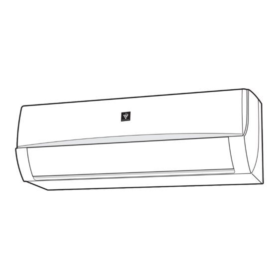
Page 4: Part Names
7 Horizontal Airflow Louvre 8 Outlet (Air) 9 OPERATION Lamp (red 10 TIMER Lamp (orange 11 POWERFUL JET Lamp (green 12 PLASMACLUSTER Lamp (blue AH-PN10, AH-PN10-GY AH-L10 AH-PN13, AH-PN13-GY AH-L13 OUTDOOR UNIT 13 Inlet (Air) 14 Refrigerant Pipe and AU-PN10... -
Page 5: Ah-Pn19, Ah-Pn24
INDOOR UNIT 1 Inlet (Air) 2 Open Panel 3 Air Filter 4 AUX Button 5 Receiver Window 6 Power Supply Cord 7 Vertical Airflow Louvre 8 Horizontal Airflow Louvre 9 Outlet (Air) 10 PLASMACLUSTER Lamp (blue 11 OPERATION Lamp (red OUTDOOR UNIT 12 TIMER Lamp (orange 13 POWERFUL JET Lamp... - Page 6 2 DISPLAY 3 ON/OFF Button 4 THERMOSTAT Button 5 DISPLAY Button 6 ONE-HOUR OFF TIMER Button 7 PLASMACLUSTER Button (AH-PN10, AH-PN10-GY AH-PN13, AH-PN13-GY AH-PN19, AH-PN24 ONLY) 8 TIMER ON Button 9 MODE Button 10 TIMER OFF Button 11 FAN Button...
-
Page 7: Using The Remote
USING THE REMOTE CONTROL AUXILIARY MODE LOADING BATTERIES Use this mode when the remote control is not available. Remove the battery cover. TO TURN ON Insert two batteries. (AAA(R03)) Press the AUX button. Make sure the ( ) and ( ) polarities are correctly aligned. -
Page 8: Basic Operation
BASIC OPERATION Press the MODE button to select the operation mode. AUTO COOL Press the ON/OFF button to start operation. • The red OPERATION lamp ( ) will light up. TO TURN OFF Press the ON/OFF button again. • The red OPERATION lamp ( ) will turn off. -
Page 9: Adjusting The Air
ADJUSTING THE AIR FLOW POWERFUL JET OPERATION DIRECTION The air conditioner works at the maximum VERTICAL AIR FLOW DIRECTION power and optimum louvre direction to makes the room cool rapidly. Press the SWING button. • The vertical airflow louvre will swing. During operation, press the Press the SWING button again POWERFUL JET button. -
Page 10: Operation
GENTLE COOL AIR PLASMACLUSTER OPERATION The vertical airflow louvre is set obliquely (AH-PN10, AH-PN10-GY upward to deliver cool air to the ceiling in AH-PN13, AH-PN13-GY order to avoid direct airflow. AH-PN19, AH-PN24 ONLY) During operation, press the Plasmacluster ions released into the room GENTLE COOL AIR button. -
Page 11: Timer Operation
TIMER OPERATION TIMER ON TIMER OFF Press the TIMER OFF button and Press the TIMER ON button and set the time as desired. set the time as desired. 0.5h 1.0h 1.5h 0.5h 1.0h 1.5h • The orange TIMER lamp ( ) will light up. -
Page 12: One-Hour Off Timer
ONE-HOUR OFF TIMER DISPLAY BUTTON When the ONE-HOUR OFF TIMER is set, the Use when the lamps on the unit are too unit will automatically turn off after one hour. bright. (The red OPERATION lamp and the orange TIMER lamp cannot be turned off.) Press the ONE-HOUR OFF TIMER button. -
Page 13: Maintenance
MAINTENANCE MAINTENANCE AFTER AIR Be sure to disconnect the power cord from the wall outlet or turn off the circuit breaker CONDITIONER SEASON before performing any maintenance. Operate the unit in the COOL CLEANING THE FILTERS mode, temperature setting 30˚C, Turn off the unit. -
Page 14: Before Calling For
Please call for service when air discharged. OPERATION lamp, TIMER lamp and/or PLASMACLUSTER lamp on the unit blink. ODOR EMITTED FROM THE PLASMACLUSTER AIR OUTLET (AH-PN10, AH-PN10-GY AH-PN13, AH-PN13-GY (AH-PN10, AH-PN10-GY AH-PN19, AH-PN24 ONLY) AH-PN13, AH-PN13-GY AH-PN19, AH-PN24 ONLY) This is the smell of ozone generated from the Plasmacluster Ion generator. -
Page 15: Installation Manual
INSTALLATION MANUAL SPLIT TYPE ROOM AIR CONDITIONER SAFETY PRECAUTIONS • Installation must be made in accordance with the installation manual by qualified service personnel. Incorrect work will cause electric shock, water leak, fire. • Be sure to use the attached accessories parts and specified parts for installation. Use of other parts will cause electric shock, water leak, fire, the unit falling. -
Page 16: Installation Diagram
NOTES ON LOCATIONS INDOOR UNIT 1. Keep the air outlet clear of any obstacle so that outgoing air flows smoothly in the entire room. 2. Make a drain hose hole for easy drainage. 3. Provide sufficient space on both sides and above the unit. 4. - Page 17 PIPES Max. piping Max. height Min. piping Additional refrigerant Model length:A difference:B length (piping length exceeds 7.5m) 9K-Btu/h type 10 m 15 g/m 12K-Btu/h type 15 m 10 g/m 18K 24K-Btu/h type 15 m 10 m • Standard piping length is 7.5m. •...
- Page 18 SETTING UP THE INDOOR UNIT Model 9000/12000 BTU Piping route For directions 1, 2 , 4 and 5, cut out the specific zone without leaving any sharp edge. (Keep the cut-out plate for possible future use.) Mounting the indoor unit PLATE...
- Page 19 Model 18000/24000 BTU Piping route For directions 1, 2 , 4 and 5, cut out the specific MOUNTING PLATE zone without leaving any sharp edge. (Keep the cut-out plate for possible future use.) Taping Plate Hook Plate MOUNTING PLATE Cut the plate along notch.
-
Page 20: Connecting The Drain Hose
(1) Process the end of the connecting Model 9000/12000 BTU cable for the indoor side. (2) Open the open panel. (3) Connect the cable. (4) Fix the cable with the cable cover and the short screw. Earth wire (5) Close the open panel. 5 CABLE COVER SHORT SCREW Connecting... -
Page 21: Outdoor Unit Installation
ระยะห า งของขาตั ้ ง ตั ว เครื่ องปรั บ อากาศ ระยะห า งของขาตั ้ ง ตั ว เครื่ องปรั บ อากาศ Model 9K/12K Btu/h 18K Btu/h 24K Btu/h Length unit: mm Unit size AH-PN10 AH-PN19 AU-PN10 AU-PN19 AU-PN24 AH-PN10GY AH-PN24 AU-PN13... - Page 22 CONNECTING THE PIPES TO THE OUTDOOR UNIT Piping can be made in four directions, choose whichever direction convenient according to unit’s installation condition. 1. Remove 3 screws of service panel. Slide the panel downward and detach it. Screw Pipe cover 2.
- Page 23 AIR REMOVAL (1) Remove both valve shaft caps of the 2 and 3-way valves. (2) Remove the service port cap of the 3-way valve. (3) Connect the gauge manifold hose to the service port and the vacuum pump. Be sure that the hose end to be connected to the service port has a valve core pusher. (4) Open the gauge manifold low-pressure valve(Lo) and operate the vacuum pump for 10-15 minutes.
-
Page 24: Connecting The Cable To The Outdoor Unit
CONNECTING THE CABLE TO THE OUTDOOR UNIT 9K 12K-Btu/h type Connecting cable 9K 12K 18K-Btu/h type (1) Process the end of the connecting cable for the outdoor unit. Length unit: mm (2) Remove the control box cover. (3) Connect the cable. (4) Put back the control box cover. -
Page 25: Power Cabling
POWER CABLING Prepare a dedicated power supply circuit. 9K-Btu/h type 12K-Btu/h type 18K-Btu/h type 24K-Btu/h type Power supply 220 V - 240 V, single-phase Circuit breaker 10 A 15 A 20 A 25 A • Fit a disconnect switch, having a contact separation of at least 3mm in all poles, to the electricity power line. -
Page 26: Pump Down
DETACHING THE UNIT FROM THE MOUNTING PLATE Push the “ ” marks at the bottom of the indoor unit and pull the bottom of the unit. When the hooks are released from the mounting plate, support the bottom of the unit and lift the unit upwards. “... - Page 27 OM_AH-PN10 13GY_EN.indd Sec1:25 OM_AH-PN10 13GY_EN.indd Sec1:25 12/22/11 6:30:42 PM 12/22/11 6:30:42 PM...
- Page 28 Printed in Thailand TINSEA720JBRZ 11M- TH OM_AH-PN10 13GY_EN.indd Sec1:26 OM_AH-PN10 13GY_EN.indd Sec1:26 12/22/11 6:30:42 PM 12/22/11 6:30:42 PM...