Table of Contents
Advertisement
Advertisement
Table of Contents

Related Manuals for Canopus ADVC-300


Summary of Contents for Canopus ADVC-300
- Page 1 User Manual...
- Page 2 Your ADVC-300 options are covered by a limited warranty when you register your Canopus product. This warranty is for a period of three years from the date of purchase from Canopus or an authorized Canopus agent. This warranty applies only to the original purchaser of the Canopus product and is not transferable.
- Page 3 Do not disassemble Do not disassemble Do not remove the cover or modify the ADVC-300. Fire, electric shock or malfunction may result. For internal inspection or repair, please contact your system integrator or Canopus directly. Do not operate at other than the specified voltage...
- Page 4 LOWER THE VOLUME OF THE AUDIO EQUIPMENT Please lower your audio equipment speaker level that is connected with the ADVC-300 when you turn the power of the ADVC-300 ON/OFF. You may hear a loud noise when you turn the power ON/OFF.
- Page 5 Notices & Warranties CAUTION CAUTION CAUTION CAUTION CAUTION The following conditions indicate the potential for bodily harm, damage to hardware or loss of data. Do not pull AC adapter cord when disconnecting from Do not pull AC adapter cord when disconnecting from Do not pull AC adapter cord when disconnecting from Do not pull AC adapter cord when disconnecting from Do not pull AC adapter cord when disconnecting from...
- Page 6 Declaration of Conformity Declaration of Conformity Declaration of Conformity Declaration of Conformity Declaration of Conformity According to FCC Part 15 Responsible Party Name: Canopus Co.,Ltd. Address: 1-2-2 Murotani Nishi-ku, Kobe-city Hyogo 651-2241 Japan Telephone: +81-78-992-5846 Declares that productModel: ADVC-300 Complies with Part 15 of the FCC Rules.
- Page 7 Canopus, as written in both English and Japanese, and its logo are registered trademarks of Cano- pus Co., Ltd. ADVC-300 is a trademark of Canopus Co., Ltd.
-
Page 8: Table Of Contents
T able of Contents T able of Contents ADVC-300 features ......................12 Packege Contents ......................13 Items included in ADVC-300 package ..............13 Names and functions of components ................14 Front ......................... 14 Rear ........................... 15 Top ..........................16 Bottom ........................17 Setting up ADVC-300 ..................... - Page 9 T able of Contents Recording digital video to analog VCR ..............49 Technical Information ....................50 Priorities among analog input signals ..............50 Audio modes ......................50 Copyright protection feature ................... 50 Specifications .........................51 Troubleshooting ......................52...
-
Page 12: Advc-300 Features
Windows or Macintosh. Color bar signal output feature The ADVC-300 outputs color bars for reference signal from analog video output. It is handy for making adjustments on images. * Color bars are not output from DV. -
Page 13: Packege Contents
Contents ackage Contents age Contents age Contents The product package includes the following accessories. Items included in ADVC-300 package Items included in ADVC-300 package Items included in ADVC-300 package Items included in ADVC-300 package Items included in ADVC-300 package •... -
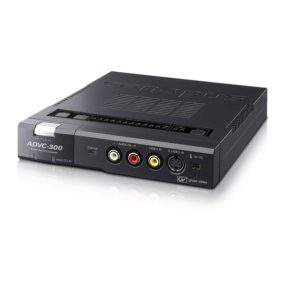
Page 14: Names And Functions Of Components
Lights while the ADCV-300 is receiving signals from the DV termi- nal and converting them to analog signals. (3) [ANALOG IN] LED Lights while the ADVC-300 is receiving signals from the analog terminal and converting them to DV signals. (4) STATUS LED Lights in red when the Macrovision signal or any anomaly has been detected. -
Page 15: Rear
(4) AUDIO OUT L/R Terminal for analog audio output. (5) DC IN 5V Connect the AC adapter that comes with the product to this termi- nal. (6) [POWER] switch Allows you to turn ON/OFF the ADVC-300. (7) COMPONENT OUT Terminal for D1 output. -
Page 16: Top
T T T T T o p (1) (2) (4) (5) (1) [ADJUST DOWN] switch When selecting an item to set up, pressing this switch moves the ADJUST LEVEL LED's current indication to the left by one. When adjusting the quality of image or sound, pressing this switch de- creases the setting value by one. -
Page 17: Bottom
(5) [ENTER] switch Use this switch to acknowledge the setting you made. Bottom Bottom Bottom Bottom Bottom (1) [SW1] DIP switches DIP switches for setting VIDEO and AUDIO modes. (2) [SW2] DIP switches DIP switches for making video settings. -
Page 18: Setting Up Advc-300
Setting up ADVC-300 Setting up ADVC-300 Setting up ADVC-300 Setting up ADVC-300 Setting up ADVC-300 NOTE [SW1] DIP switches [SW1] DIP switches [SW1] DIP switches [SW1] DIP switches [SW1] DIP switches Before changing the DIP switch settings, be sure to turn the Allow you to set various modes. - Page 19 DIP switch for it. You can set up the qual- sure to turn OFF the ADVC-300 power before setting the DIP ity of image and sound on the ADVC-300. This mode is provided switch. for using the ADVC-300 as a simple DV converter.
-
Page 20: [Sw2] Dip Switches
All the switches have been set to OFF at the time of shipment. The following functions are changeable under the PC mode. The set values are saved in the ADVC-300's memory. • Locked Audio Mode ([SW1] DIP switch No. 3) • Audio Mode ([SW1] DIP switch No. - Page 21 If set to [OFF: External Sync], the ADVC-300 synchronize the frame and subcarrier period of analog video to be output with the pulses of the incoming DV stream. If set to [ON: Internal Sync], the ADVC-300 uses its internal circuit to determine the frame period of the analog...
-
Page 22: Adjusting Image And Sound Quality
Adjusting image and sound quality Adjusting image and sound quality Adjusting image and sound quality ADVC-300 is equipped with the image and sound quality adjustment feature. You can save one setting for external (LINE) inputs. • The image and sound quality... - Page 23 Select your desired item to adjust by pressing the [ADJUST UP] or [ADJUST DOWN] switch. To change the page, select [PAGE1/2], and then press the [ENTER] switch. If the page is switched to page 2, the [PAGE1/ 2] LED lights up. Desired item Note PAGE1[-5] Image and sound...
- Page 24 Press the [ENTER] switch to select the currently cho- sen item > The [ADJUST LEVEL] LEDs will light in series from [-5] to [PAGE1/2] twice, and then the current setting value (pre- viously saved value) will be indicated. > PAGE1[-5]: When the image and sound default set- ting has been selected: All the LEDs of [ADJUST LEVEL] and [3D Processing] will blink at the same time.
- Page 25 Light < Default 128 < Deep may be distorted when the Sharpness Weak < Default 128 < Strong Volume Low < Default 237 < High ADVC-300 processes an input source with a high volume level. Setting items Settable -15~ -14~ -9~ -6~ -3~ 10~ 13~15...
- Page 26 Set the ADVC-300 [POWER] switch to [OFF]. Set the [SW2] DIP switch No. 1 to [OFF]. > The Video Audio Adjust Mode will be set to [Normal]. > This completes the setup procedure.
-
Page 27: Installing Picture Controller 300
System requirements System requirements System requirements System requirements System requirements Canopus does not gurantee all system meeting the below require- ments to work accordingly with the ADVC-300. Computer The following are the minimum requirements for using this product. Windows • CPU: Pentium III or faster •... -
Page 28: Installation (For Windows)
Installation (for Windows) The following describes the procedure for installing Picture Controller 300 on a computer running Windows XP . * You can install Picture Controller 300 without ADVC-300 connected with the computer. Insert the “ADVC-300 Applications CD” into the CD- ROM drive. - Page 29 A D V C - 3 0 0 c o m e s w i t h t h e “ProCoder Demo version”. When you want to install “ProCoder Demo”, run “ADVC-300 Applica- tions CD” > [ProCoder Trial] > [ProCoderDemo_1_25.exe].
-
Page 30: Installation (For Macintosh)
Installation (for Macintosh) The following describes the procedure for installing Picture Controller 300 on a computer running Mac OS X. * You can install Picture Controller 300 without ADVC-300 connected with the computer. Insert the “ADVC-300 Applications CD” into the CD- ROM drive. - Page 31 Click [Continue]. Read the content carefully, and click [Continue]. > Be sure to read the readme file since it contains content not covered in the manuals.
- Page 32 Click [Continue]. > The License Agreement will be displayed. Read the content carefully and click [Agree] only if you agree to it. > If you do not agree to the License Agreement, click [Dis- agree] to stop installation and notify our customer sup- port personnel in writing.
- Page 33 Click [Install]. > The installation process starts. After the installation completes, click [Close]. > The [Picture Controller 300] folder is created in the [Ap- plications] folder.
-
Page 34: How To Use Picture Controller 300
Windows or Windows or Windows NOTE Connect the ADVC-300 to the computer, boot up the When the ADVC-300 power is OFF, set the [SW1] DIP switch No. computer, and set the [POWER] switch to [ON]. 8 to [ON: PC] (PC mode) before-... - Page 35 Click the [Start] menu, point to [All Programs], and click [Canopus Picture Controller 300]. • About Picture Controller 300 setup screen (Refer to P. 37 to [Open Preview] ([Close Pre- > Picture Controller 300 will start up. view]) button Opens the preview screen (closes the preview screen).
-
Page 36: For Windows
Macintosh or Macintosh or Macintosh NOTE Connect the ADVC-300 to the computer, boot up the When the ADVC-300 power is OFF, set the [SW1] DIP switch No. computer, and set the [POWER] switch to [ON]. 8 to [ON: PC] (PC mode) before- hand (Refer to P .19). -
Page 37: [Basic] Tab
[Basic] tab [Basic] tab [Basic] tab [Basic] tab [Basic] tab This tab page is provided for adjusting the image and sound quality. • Image Setting Allows you to adjust the brightness, contrast, saturation, hue, and sharpness of your video. • Audio Setting Allows you to adjust the volume, high and low tones and AGC gain of video. -
Page 38: [Filter] Tab
[Filter] tab can not set. • Video Processing [Y/C Separation 2D] When displaying composite video, the ADVC-300 separates the luminance (Y) and chrominance (C) signals based on the scan- ning lines above and below. [Y/C Separation 3D]... - Page 39 The digital 3D noise reduction feature employed by ADVC-300, however, removes noise after detecting noise using the charac- teristic of noise (noise has little relation to others in the time axis), the advert effect to the image is kept minimal.
-
Page 40: [Video1] Tab
[Video1] tab [Video1] tab [Video1] tab [Video1] tab [Video1] tab This tab page is provided to set the correction for color graduation. If this correction is enabled for a video having black or white crushes, the video is adjusted and become clear and crisp. •... - Page 41 • White Peak Adjust Corrects a whiteout image by correcting the gain of white (high brightness) areas and thus restoring the contrast in them. [Adjustment] Allows you to set the level of white peak adjustment. The higher the level, the lower the white peak will be. [Base Level] Allows you to specify up to which level of brightness you want to correct the white peak.
-
Page 42: [Video2] Tab
[Video2] tab [Video2] tab [Video2] tab [Video2] tab [Video2] tab This tab page is provided to sets up the edge correction and AGC. • Edge Adjustment Corrects the edge of human or object profiles in videos. [Horizontal Edge] Corrects horizontal edges in video. Vertical edges are thus en- hanced. - Page 43 • Video AGC Sets up the AGC feature for video in detail. Checkmark this option if you want to automatically set the brightness of the entire video to AGC is an acronym of “Auto Gain an optimal level. Control” and the function to auto- [AGC] matically adjust the image gradu- If [Auto] is checkmarked, the brightness of the entire video will...
-
Page 44: [Audio] Tab
Select this option when you want to create DVD videos. the UNIT mode. [32kHz 12bit] Audio data will be processed as 4-channel 12-bit data at 32 kHz. ADVC-300 processes only the main 2 channels and no sound is recorded in the 2 sub-channels. -
Page 45: [Version Info] Tab
[Version Info] tab ersion Info] tab ersion Info] tab ersion Info] tab ersion Info] tab This tab page shows the version information of Picture Controller 300. -
Page 46: Connecting Advc-300
Connecting ADVC-300 Connecting ADVC-300 Connecting ADVC-300 Connecting ADVC-300 Connecting ADVC-300 Analog video input Analog video input Analog video input Analog video input Analog video input NOTE Make connections between devices as shown in the figure. Before connecting/disconnecting a DV cable, be sure to turn OFF the power of your computer and ADVC-300. -
Page 47: Capturing Analog Video Into Computer
Do not turn ON/OFF the ADVC- Press the [POWER] switch on the rear. 300 power when the computer connected to the ADVC-300 via a DV cable is OFF or in the standby mode. Otherwise, your computer may become unbootable depend- By pressing the [INPUT SELECT] switch on the front, ing on the OHCI card being used. -
Page 48: Digital Video Input
Do not turn ON/OFF the ADVC- Receptacle 300 power when the computer AC adapter connected to the ADVC-300 via a DV cable is OFF or in the standby mode. Otherwise, your computer may become unbootable depend- ing on the OHCI card being used. -
Page 49: Watching Digital Video On Tv Monitor
W atching digital video on TV monitor atching digital video on TV monitor atching digital video on TV monitor atching digital video on TV monitor atching digital video on TV monitor Press the [POWER] switch on the rear. By pressing the [INPUT SELECT] switch, switch the input mode to DIGITAL IN. -
Page 50: Technical Information
32kHz/12-bit mode In this mode, 4 channels of 12-bit audio signals are recorded at 32kHz. When ADVC-300 is used for recording, audio data is recorded in only the 2 main channels and no sound is recorded in the 2 sub-channels. -
Page 51: Specifications
Output S-Video(MiniDIN 4 Pin)x1 RCA jack Compositex1 Analog Audio Data 48kHz 16bit 2ch 32kHz 12bit 4ch (ADVC-300 processes only the main 2 channels and not other 2 sub-channels.) Front terminal Input RCA jack x2(L/R) Rear terminal Output RCA jack x2(L/R) -
Page 52: Troubleshooting
3 seconds or more without a break. The buttons on the > The mode selection [SW1] DIP switch No ADVC-300 are not op- .8 is set to ON. In this mode, the ADVC- erable. 300 is operable only from the computer. - Page 54 F157311042...
Need help?
Do you have a question about the ADVC-300 and is the answer not in the manual?
Questions and answers