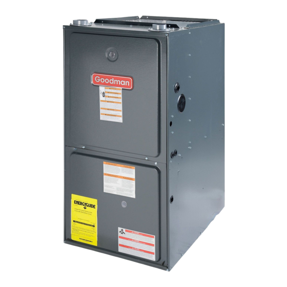
Goodman GMH95 Installation Instructions Manual
Gmh95/gch95/gme95/gch9 series gas-fired warm air furnace
Hide thumbs
Also See for GMH95:
- Installation instructions manual (37 pages) ,
- Technical manual (17 pages) ,
- Product specifications (13 pages)
Table of Contents
Advertisement
GMH95/GCH95/GME95/GCH9
G
(Type FSP CATEGORY IV Direct or Non Direct Vent Air Furnace)
ATTENTION INSTALLING PERSONNEL
As a professional installer you have an obligation to know the product better than the customer. This includes all safety
Prior to actual installation, thoroughly familiarize yourself with this Instruction Manual. Pay special attention to all safety
warnings. Often during installation or repair it is possible to place yourself in a position which is more hazardous than
Remember, it is your responsibility to install the product safely and to know it well enough to be able to instruct a customer
Safety is a matter of common sense...a matter of thinking before acting. Most dealers have a list of specific good safety
The precautions listed in this Installation Manual are intended as supplemental to existing practices. However, if there is
a direct conflict between existing practices and the content of this manual, the precautions listed here take precedence.
IO-299O
12/11
-F
W
AS
IRED
I
NSTALLATION
Installer: Affix all manuals adjacent to the unit.
These furnaces comply with requirements
embodied in the American National Stan-
dard / National Standard of Canada ANSI
Z21.47·CSA-2.3 Gas Fired Central Fur-
naces.
RECOGNIZE THIS SYMBOL AS A SAFETY PRECAUTION.
precautions and related items.
when the unit is in operation.
NOTE: Please contact your distributor or our website
for the applicable Specification Sheet referred to in this manual.
Goodman Manufacturing Company, L.P.
5151 San Felipe, Suite 500, Houston, TX 77056
www.goodmanmfg.com
2006-2011 Goodman Manufacturing Company, L.P.
©
A
ARM
IR
I
NSTRUCTIONS
in its safe use.
practices...follow them.
F
URNACE
®
US
C
Advertisement
Table of Contents
Troubleshooting

Related Manuals for Goodman GMH95


Summary of Contents for Goodman GMH95
- Page 1 GMH95/GCH95/GME95/GCH9 IRED URNACE NSTALLATION NSTRUCTIONS Installer: Affix all manuals adjacent to the unit. (Type FSP CATEGORY IV Direct or Non Direct Vent Air Furnace) These furnaces comply with requirements embodied in the American National Stan- ® dard / National Standard of Canada ANSI Z21.47·CSA-2.3 Gas Fired Central Fur-...
-
Page 2: Table Of Contents
Table of Contents .................. 4 MPORTANT OTE TO THE WNER REGARDING RODUCT ARRANTY I. Component Identification ............................. 5 II. Safety ..................................6 (ESD) P ......................6 LECTROSTATIC ISCHARGE RECAUTIONS III. Product Application .............................. 6 IV. Location Requirements & Considerations ....................7 .................................. - Page 3 ............33 ILTERS ECTION EFORE NSTALLING ETURN UCTWORK ............................33 PRIGHT NSTALLATIONS ............................33 ORIZONTAL NSTALLATIONS XIV. Startup Procedure & Adjustment ........................33 ............................33 NTICIPATOR ETTING ............................... 33 RAIN RIMING ..............................33 URNACE OPERATION ........................34 UPPLY RESSURE EASUREMENT ..................
-
Page 4: I N O P W
HIPPING NSPECTION WARNING All units are securely packed in shipping containers tested accord- ing to International Safe Transit Association specifications. The car- F THE INFORMATION IN THESE INSTRUCTIONS IS NOT FOLLOWED ton must be checked upon arrival for external damage. If damage is EXACTLY A FIRE OR EXPLOSION MAY RESULT CAUSING PROPERTY found, a request for inspection by carrier’s agent must be made in... -
Page 5: Component Identification
I. COMPONENT IDENTIFICATION Upflow/Horizontal Counterflow/Horizontal Gas Valve 22 Blower Door Interlock Switch Gas Line Entrance (Alternate) 23 Capacitor Pressure Switch 24 Integrated Control Module Gas Manifold (with fuse and diagnostic LED) Combustion Air Intake Connection / “Coupling” 25 24-Volt Thermostat Connections Hot Surface Igniter 26 Transformer (40 VA) Rollout Limit... -
Page 6: Safety
II. SAFETY or shuffle your feet, do not touch ungrounded objects, etc.). If you come in contact with an ungrounded object, repeat Please adhere to the following warnings and cautions when in- step 2 before touching control or wires. stalling, adjusting, altering, servicing, or operating the furnace. 4. -
Page 7: Location Requirements & Considerations
• 100% outside air is provided for combustion air The rated heating capacity of the furnace should be greater than or requirements during construction. Temporary ducting can equal to the total heat loss of the area to be heated. The total heat be used. -
Page 8: Clearances And Accessibility
• Exposure to contaminated combustion air will result in A furnace installed in a confined space (i.e., a closet or utility room) must have two ventilation openings with a total minimum free area safety and performance-related problems. Do not install of 0.25 square inches per 1,000 BTU/hr of furnace input rating. -
Page 9: Thermostat Location
bustion and ventilation air for gas fired and other fuel burning appli- e. Test for draft hood equipped spillage at the draft hood relief opening ances. Appliances that pull air out of the house (clothes dryers, after 5 minutes of main burner operation. Use the flame of a match exhaust fans, fireplaces, etc.) increase the problem by starving or candle;... - Page 10 Space, Unconfined. 2. When communicating with the outdoors through vertical ducts, each opening shall have a minimum free area of 1 square inch per For purposes of this Code, a space whose volume is not less than 50 4,000 BTU per hour of total input rating of all equipment in the cubic feet per 1,000 BTU per hour of the aggregate input rating of all enclosure.
-
Page 11: Installation Positions
NOTE: The single opening must have VII. HORIZONTAL APPLICATIONS & CONSIDERATIONS a free area of not less than one Chimney or Gas Vent square inch per 3000 BTU of ENERAL the total input rating of all equip- ment in the enclosure, but not less than Horizontal applications, in particular, may dictate many of the the sum of the areas of all vent connectors in the confined space. -
Page 12: Alternate Electrical And Gas Line Connections
UPRIGHT For installations above 7000 feet, please refer to your distributor ALTERNATE FLUE AND COMBUSTION AIR PIPE for required kit(s). ALTERNATE FLUE LOCATIONS PIPE LOCATION GMH95, GCH95, GCH9 GAS ORIFICE CHART Bottom Bottom Manifold Pressure Return Return Altitude Orifice... -
Page 13: Dual Certification : Non -Direct /Direct Vent
As an alternative to PVC pipe, primer, solvent cement, and fittings, WARNING ABS materials which are in compliance with the following specifi- cations may be used. Two-or-three-inch ABS Schedule 40 pipe must meet ASTM D1527 and, if used in Canada, must be CSA PON COMPLETION OF THE FURNACE INSTALLATION CAREFULLY listed. - Page 14 DIRECT VENT TERMINAL CLEARANCES Canadian Installations U.S. Installations Canadian Installations U.S. Installations Clearance to service 3 ft. (91 cm). A= Clearance above grade, 12 in. (30 cm) 12 in. (30 cm) regulator vent outlet. veranda, porch, deck or balcony. (See 1.24.6-i(9)b.) J= Clearance to nonmechanical air 6 in.
-
Page 15: Termination Locations
ERMINATION OCATIONS Vent/flue pipe can be secured to the vent/flue coupling using the NOTES: Refer to Section IV, Location Requirements and rubber coupling and worm gear hose clamps provided with this Considerations for combustion air contaminant restrictions. furnace (see “Standard Connections” figure). The rubber coupling allows separation of the vent/flue pipe from the furnace during The following bullets and diagram describe the restrictions con- servicing. -
Page 16: Alternate Furnace Connections
COMBUSTION Counterflow units. VENT/FLUE COMBUSTION AIR PIPE VENT/FLUE PIPE AIR PIPE PIPE (DIRECT VENT ONLY) (DIRECT VENT ONLY) Cut the vent/flue pipe 3.75 inches from the blower deck coupling. See Vent/Flue Pipe Cuts figure. Save vent/flue pipe 90º PVC RUBBER 90º... -
Page 17: On Irect Ent Ingle Ipe Iping
ENGTHS AND IAMETERS REMOVE REMOVE REMOVE REMOVE Refer to the following table for applicable length, elbows, and PIPE 4 SCREWS 4 SCREWS PIPE CUT PIPE PER pipe diameter for construction of the vent/flue pipe system of a VENT/FLUE PIPE CUTS DIAGRAM CUT PIPE PER non-direct vent installation. -
Page 18: Direct Vent (Dual Pipe ) Piping
Direct vent installations require both a combustion air intake and a TEE (OPTIONAL) vent/flue pipe. The pipes may be run horizontally and exit through the side of the building or run vertically and exit through the roof of 12 " Min To Roof Or Highest Anticipated the building. - Page 19 TEE (OPTIONAL) 12" MIN 3" MIN VENT/FLUE SUPPORT 24" MAX STRAPS COMBUSTION AIR INTAKE VENT/FLUE TEE (OPTIONAL) 12" MIN. COMBUSTION SCREEN AIR INTAKE OPTIONAL 12" MIN. ABOVE SCREEN HIGHEST ANTICIPATED (OPTIONAL) 12" MIN. ABOVE SNOW LEVEL HIGHEST ANTICIPATED SNOW LEVEL 90°...
-
Page 20: Concentric Vent Termination
In horizontal installations, the drain hoses will exit through the bottom (down side) of the unit with the drain trap suspended be- neath the furnace. The field-supplied drain system must be in Vents 90° Medium accordance with all local codes and the instructions in the follow- Radius Elbows ing sections. - Page 21 2. Secure Hose A to front cover drain port with a red hose TANDARD IGHT OR RAIN ONNECTIONS clamp. Route hose to rear side panel grommet hole. All installations positions require the use of the drain trap, hoses, 3. Cut and remove 1/4 inch from the end of the drain port on tubes, and clamps.
- Page 22 5. Insert Tube 1 into rubber elbow drain port and secure with a LTERNATE RAIN ONNECTIONS silver hose clamp. Angle tube toward trap. Upright installations using the alternate vent/flue outlet will require 6. Cut 17 3/4 inches from the long end of Hose B and discard. “right-side only”...
- Page 23 5. Cut “X” inches from the long end of Hose B and discard. PRIGHT NSTALLATIONS RAP ON Refer to table for appropriate length to cut. Secure remaining NOTE: For left side trap installation, grommets must be moved to hose to Tube 1 with a green hose clamp. Route other end the left side of the furnace and the plugs installed on the right side of Hose B to front left side panel grommet hole.
-
Page 24: Horizontal Installations
1. Remove the rubber plug from right side of the front cover "X" Length to Cut From Long drain port. Cabinet Width Models End of Hose B (inches) (kBTU_Tons) Counterflow furnaces (inches) Relocate the front cover pressure switch hose connection 040_3, 045_30, from the left side pressure tap to the right (down) side tap. - Page 25 4. Remove the rubber cap from the side drain port on the rubber elbow. Horizontal installations with the left side panel down will require 5. Secure the short end of Hose B to rubber elbow side drain drain hoses to be connected to the left side front cover drain port port using a green hose clamp.
-
Page 26: Electrical Connections
XI. ELECTRICAL CONNECTIONS Line polarity must be observed when making field connections. Line voltage connections can be made through either the right or left side panel. The furnace is shipped configured for a left side WARNING (right side for counterflows) electrical connection with the junction box located inside the burner compartment. -
Page 27: Volt Thermostat Wiring
24 V HERMOSTAT IRING NOTE: Wire routing must not interfere with circulator blower ECO-TECH MOTOR operation, filter removal, or routine maintenance. Low voltage connections can be made through either the right or left side panel. Thermostat wiring entrance holes are located in the blower compartment. -
Page 28: Volt Humidifier
If it is necessary for the installer to supply additional line voltage In some areas the gas supplier may artificially derate the gas in an wiring to the inside of the furnace, the wiring must conform to all effort to compensate for the effects of altitude. If the gas is artifi- local codes, and have a minimum temperature rating of 105°C. - Page 29 • Natural Gas Capacity of Pipe Use ground joint unions. In Cubic Feet of Gas Per Hour (CFH) • Install a drip leg to trap dirt and moisture before it can enter Length of Nominal Black Pipe Size Pipe in Feet 1/2"...
- Page 30 GAS VALVE MANIFOLD SHUT OFF VALVE (UPSTREAM FROM GAS LINE PIPE UNION) PLUG IN PLUG IN ALTERNATE GAS LINE GAS LINE HOLE HOLE GAS LINE HOLE GAS VALVE DRIP LEG PIPE UNION DRIP LEG MANUAL SHUT-OFF VALVE JOINT PIPE UNION) PIPE UNION DRIP LEG GAS VALVE...
-
Page 31: Propane Gas Tanks And Piping
IPING HECKS 5 to 15 PSIG First Stage (20 PSIG Max.) Before placing unit in operation, leak test the unit and gas connec- Regulator Continuous 11" W.C. tions. 200 PSIG Second Stage Maximum Regulator WARNING O AVOID THE POSSIBILITY OF EXPLOSION OR FIRE NEVER USE A MATCH OR OPEN FLAME TO TEST FOR LEAKS Propane Gas Installation (Typ.) -
Page 32: Checking Duct Static
A closed return duct system must be used, with the return duct connected to the furnace. NOTE: Ductwork must never be attached to the back of the furnace. Flexible joints may be used for supply and return connections to reduce noise transmission. To prevent the blower from interfering with combustion air or draft when a central return is used, a connecting duct must be installed be- tween the unit and the utility room wall. -
Page 33: Upright Installations
installed without a cooling coil, it is recommended that a remov- FILTER able access panel be provided in the outlet air duct. This opening ACCESS shall be accessible when the furnace is installed and shall be of DOOR such a size that the heat exchanger can be viewed for visual light inspection or such that a sampling probe can be inserted into the RETURN air stream. -
Page 34: Gas Supply Pressure Measurement
5. Move the furnace gas valve manual control to the OFF Open to Atmosphere position. 6. Wait five minutes then smell for gas. Be sure to check near High Fire Regulator the floor as some types of gas are heavier than air. Outlet Adjust Regulator... -
Page 35: As Anifold Ressure Easurement And Djustment
3. Outlet pressure tap connections: NOTE: If measuring gas pressure at the drip leg or Honeywell a. Honeywell VR9205 valve: Remove the outlet pressure VR9205 gas valve, a field-supplied hose barb fitting must be installed boss plug. Install an 1/8" NPT hose barb fitting into the prior to making the hose connection. -
Page 36: Temperature Rise
1. Operate furnace with burners firing for approximately ten minutes. Ensure all registers are open and all duct dampers are in their final (fully or partially open) position. GMH95, GCH95, GCH9 Circulator Blower Speeds 2. Place thermometers in the return and supply ducts as close to the furnace as possible. -
Page 37: Setting Furnace Operating Mode
• As shipped, the circulator blower fan will remain on for 150 sec- Integrated control module LED will light. onds after the gas valve closes. When a call for cooling occurs, the • Integrated control module monitors safety circuits circulator fan comes on and remains on for 45 seconds after the continuously. -
Page 38: Cooling Mode
• • Furnace operates; integrated control module monitors Circulator blower is de-energized. Electronic air cleaner safety circuits continuously. terminals are de-energized. • • If low-stage delay period expires, control will shift operation Furnace awaits the next call from thermostat. from low-stage heating mode operation to high-stage XVI. -
Page 39: Pressure Switches
RESSURE WITCHES AULT ECALL The pressure switches are normally-open (closed during opera- The ignition control is equipped with a momentary pushbutton tion), single-pole single-throw, negative air pressure-activated switch that can be used to display on the diagnostic LED the last switches. -
Page 40: Filters
• Drainage system. Check for blockage and/or leakage. URNERS Check hose connections at and internal to furnace. Visually inspect the burner flames periodically during the heating season. Turn on the furnace at the thermostat and allow several • Wiring. Check electrical connections for tightness and/or minutes for flames to stabilize, since any dislodged dust will alter corrosion. -
Page 41: Before Leaving An Installation
6. Remove the recuperator coil turbulators individually by slowly XX. BEFORE LEAVING AN INSTALLATION pulling each turbulator forward firmly. • Cycle the furnace with the thermostat at least three times. 7. Clean the recuperator coil tubes using a long handle wire Verify cooling and fan only operation. -
Page 42: Troubleshooting Chart
TROUBLESHOOTING CHART Associated Associated Symptoms of Abnormal Fault Description(s) Possible Causes Fault Description(s) Possible Causes Corrective Action Cautions and Notes Operation LED Code LED Code • Furnace fails to operate. NONE • No 115 volt power to • Manual disconnect switch •... - Page 43 TROUBLESHOOTING CHART Fault Associated Symptoms of Cautions Corrective Action Possible Causes Description(s) LED Code Abnormal Operation & Notes • Check primary limit. • Insufficient conditioned air • Turn power OFF • Circulator blower runs • Primary limit Replace if necessary. over the heat exchanger.
-
Page 44: Blower Performance Data
BLOWER PERFORMANCE DATA GMH95 BLOW ER PERFORMANCE (CFM & Tem perature Rise vs. External Static Pressure) Tons AC EXTERNAL STATIC PRESSURE (Inches W ater Column) Model Motor at 0.5" Heating Speed Speed A s Shipped CFM RISE CFM RISE CFM RISE CFM RISE CFM RISE CFM CFM CFM... - Page 45 BLOWER PERFORMANCE DATA GCH95 / GCH9115 BLOWER PERFORMANCE (CFM & Temperature Rise vs. External Static Pressure) EXTERNAL STATIC PRESSURE (Inches Water Column) Tons AC Model Motor at 0.5" Heating Speed Speed As Shipped CFM RISE CFM RISE CFM RISE CFM RISE CFM RISE CFM CFM CFM 1415 1352 1290...
- Page 46 BLOWER PERFORMANCE DATA GME95 (CFM & TEMPERATURE RISE VS. EXTERNAL STATIC PRESSURE) EXTERNAL STATIC PRESSURE (Inches Water Column) Model Tons -------------- Motor AC at Heating Speed Speed 0.5" As Shipped RISE RISE RISE RISE RISE T1 - YELLOW T2 - RED GME950403BX* T3 - ORANGE 1121...
- Page 47 GCH9_AA/AB & GMH95[0453,0704,0905]_AB WIRING DIAGRAM GMH95[0703,0904,1155]_AC 2N D S TAGE DELAY MODE HEAT DELAY NOTE 6 COOL-H 6. TO RECALL THE LAST 5 FAULTS, MOST RECENT TO LEAS T RECENT, DEPRESS SWITCH FOR MORE THAN 2 SECONDS WHILE IN STANDBY (NO THERMOSTAT INPUTS)
-
Page 48: Wiring Diagram
GMH95[0453,0704,0905]_AC WIRING DIAGRAM GMH95[0703,0904,1155]_AD BLOWER INTEGRATED HUMIDIFIER 24 VAC COMPARTMENT CONTROL MODULE HUMIDIFIER DOOR SWITCH TR (6) (OPEN WHEN 24 VAC DOOR OPEN) GND (8) 40 VA TRANSFORMER MVC (9) 115 VAC VALVE MVH (12) 24V THERMOSTAT CONNECTIONS MVL(2) ID BLOWER... - Page 49 GCH95_AA / GCH9_AC WIRING DIAGRAM GMH950905CXA* BLOWER 24 VAC INTEGRATED HUMIDIFIER COMPARTMENT HUMIDIFIER CONTROL MODULE DOOR SW ITCH TR (6) (OPEN WHEN DOOR OPEN) GND (8) VALVE MVC (9) MVH (12) 24V THERMOSTAT CONNECTIONS MVL(2) FRONT COVER PS (10) PRESSURE SWITCH PSO (4) FUSE MICRO...
- Page 50 GME95 WIRING DIAGRAM Wiring is subject to change. Always refer to the wiring diagram on the unit for the most up-to-date wiring.
- Page 51 THIS PAGE LEFT INTENTIONALLY BLANK...
- Page 52 Goodman Manufacturing Company, L.P. 5151 San Felipe, Suite 500, Houston, TX 77056 www.goodmanmfg.com 2006-2011 Goodman Manufacturing Company, L.P. ©...
Need help?
Do you have a question about the GMH95 and is the answer not in the manual?
Questions and answers