Table of Contents
Advertisement
Advertisement
Table of Contents

Related Manuals for FRIEDLAND SA5


Summary of Contents for FRIEDLAND SA5
- Page 1 6 Zone Communicating Wirefree Alarm System Installation & Operating Manual...
-
Page 2: Device Range
The amount by which the range will be reduced is close proximity to the Siren due to the high sound level dependant upon the nature of the barrier. e.g. produced by this device. Friedland SA5 6 Zone Communicating Wirefree Alarm System... -
Page 3: Table Of Contents
CONTENTS Page No. Page No. TESTING THE SYSTEM KIT CONTENTS Initial Testing Testing an Installed System INTRODUCTION AND OVERVIEW Multiple Users DEFAULT SETTINGS System Arming Reset Factory Default Conditions Entry/Exit Delay Zones PROGRAMMING Zone Lockout Navigating through the Programming Quick Set Mode Menus Telephone Application Setup Final Exit Set Zone... -
Page 4: Kit Contents
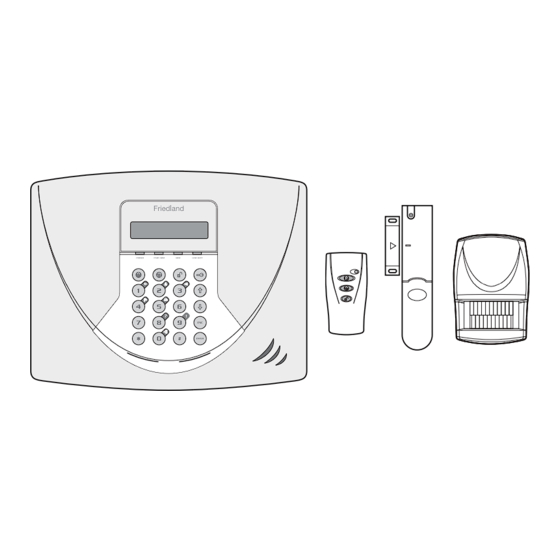
KIT CONTENTS Alarm System should contain the following components. 1 x Control Panel 1 x Remote Control 1 x PIR Movement Detector 1 x Magnetic Contact Detector Also included: Telephone Connection Lead Power Supply Adaptor Control Panel Installation & Operating Manual Fixing pack Batteries WP1.2-6... -
Page 5: Introduction And Overview
INTRODUCTION AND OVERVIEW MULTIPLE USERS Delay is disabled then detectors on active zones will immediately be able to initiate an alarm as soon as the The system allows for up to 6 Users and a Master User system begins to arm. to be configured. -
Page 6: Quick Set
“Entry-Route” will operate as normal This is an independent service not provided by Novar according to their normal configuration. Friedland. Note: The zone configured as the “Entry Door” must be Note: Remote Manager may not be... -
Page 7: Answer-Phone
For example, the latchkey facility is useful to inform periods of 10 seconds in a 5 minute interval, this will parents that a child has returned from school and also generate a Full Alarm condition. disarmed the system. The Jamming Detection circuit is designed to permanently scan for jamming signals. -
Page 8: Planning Your Alarm System
PLANNING YOUR ALARM SYSTEM Before attempting to install your Alarm System it is TYPICAL INSTALLATION important to study your security requirements and plan The following example below shows typical property your installation. incorporating the suggested positions for the Control Panel, PIR and Magnetic Contact Detectors and PIR Movement Detectors are used to protect the main optional Solar Siren. -
Page 9: Remote Control Unit
The system default settings are pre-configured to REMOTE CONTROL UNIT provide a basic functional system to suit most typical The Remote Control Unit(s) are used to Arm, Part-Arm basic installations: and Disarm the system. Zone 1 is configured as a Delay zone with a 30s entry/exit delay. -
Page 10: Control Panel
Ensure that the jumper link located immediately Note: If small children are in the household, a below the House Code DIP switches is fitted in further consideration should be given to keeping position for use with this alarm system. the units out of their reach. It is recommended that the Control Panel should Insert the battery under the clip ensuring that the be positioned such that the Exit/Entry tone... - Page 11 External Tamper Switch Jumper Link P51 Upper Keyhole Fixing Hole Upper Keyhole Fixing Hole – ve Terminal (Black Lead) + ve Terminal (Red Lead) + ve Terminal (Blue Lead) – ve Terminal (Blue Lead) Power Supply Cable Access Lower Fixing Hole Hole Reset Jumper...
-
Page 12: Configuring The Control Panel House Code
If required, connect the Control Panel to the Using a Remote Control: telephone line using the cable supplied by With the required House Code already inserting small RJ11 plug into socket marked LINE configured on the Remote Control, press located on the bottom edge of the Control Panel. If the cable supplied is not long enough to reach a The Control Panel will beep twice to suitable phone point then it will need extending... -
Page 13: Passive Infra Red (Pir) Movement Detectors
PASSIVE INFRA RED (PIR) MOVEMENT DETECTORS PIR detectors are designed to detect movement in a protected area by detecting changes in infra-red radiation levels caused for example when a person Detector Range (metres) moves within or across the devices field of vision. If movement is detected an alarm signal will be generated, (if the system is armed). -
Page 14: Installing And Configuring The Pir Movement Detectors
Ensure that the position selected for the PIR the Detector Panel onto plasterboard use detector is within effective range of the Control appropriate wall plugs. Panel, (refer to "Testing the Control Panel & Remote Configure the House Code for the PIR Detector by Control"). -
Page 15: Testing The Pir Movement Detectors
stabilised. The LED will then stop flashing and Use the buttons to scroll through turn OFF. the menu until ‘WALK TEST’ is displayed and press Note: If the device is configured in Walk Test ENTER mode (i.e. DIP 4 of SW3 ON) then the LED will ‘Walk Test Waiting…’... -
Page 16: Magnetic Contact Detectors
MAGNETIC CONTACT Note: Take care when fixing the Detector to a metal frame, or mounting within 1m of metalwork (i.e. DETECTORS radiators, water pipes, etc) as this could affect the radio range of the device. On uPVC Door/Window frames, it The Magnetic Contact Set comprises two parts;... -
Page 17: Testing The Magnetic Contact Detector
If fixing the detector with screws first remove the Configure the alarm zone which the detector will battery holder by carefully tilting up the end and operate on with DIP switches 9-11 as follows: pulling away from the printed circuit board. DIP 9 DIP 10 DIP 11... -
Page 18: External Connections
Control Panel will beep to indicate that an Control Unit incorporates a terminal block for alarm signal has been received and ‘Accessory connection of hard-wired Zones (7-10) or Siren. The Tamper’ will be displayed. connection terminal block is located inside the Control Panel behind the front cover. -
Page 19: Testing The System
TESTING THE SYSTEM TEST MODE Code: WALK TEST ALARM TEST Wirefree Siren Voice Dialler Remote Manager Service ON/OFF Test Test press ENTER press ENTER press ENTER press ENTER press ENTER Walk Test Service ON/OFF Test phone No._ Remote Manager Waiting… Stop->ESC Wait for 10s Test…wait... -
Page 20: Alarm Test
ALARM TEST VOICE DIALLER TEST Scroll through the top level Test Mode menu until 1. Scroll through the top level Test Mode menu until ‘ALARM TEST’ is displayed and press ENTER ‘VOICE DIALER TEST’ is displayed and press ENTER Scroll through the menu until the required alarm is displayed and press to operate the selected ENTER... -
Page 21: Default Settings
DEFAULT SETTINGS USER SETUP TIME & DATE Users 1-6: Not programmed Time: 12:00:00 Master User Access Code: 1234 Date: 01/01/02 SYSTEM SETUP LATCHKEY SETUP House Code: Not programmed Status: Alarm Time: ON, 180s Selected User Setup: OFF (all users) Wirefree Siren: Phone Numbers: Not programmed RF Jamming Detection:... -
Page 22: Programming
PROGRAMMING INSTRUCTIONS With the system in Standby Mode. Press ENTER Master User Access Code The system is now in the Programming Mode Navigating through the Programming Mode Menus programmable system parameters are arranged by Press ENTER groups in a series of menus within programming mode. a) select the displayed menu, or Each menu (and sub-menu) will contain all programmable b) change the displayed parameter setting, or... -
Page 23: Telephone Application Setup
Telephone Application Setup also record a 4s message to be used with the “Latch- Key” feature. If using any of the telephone based functionality, (e.g. answer-phone voice dialler, remote phone access & Note: For the Latch-Key feature to operate correctly the control etc.) the dial method must be set according to “Dial Method”... -
Page 24: System Setup
Replay User Latch-Key Message Scroll through the menu until ‘:1 Access Code’ (and Scroll through the menu until ‘:3 Replay User the current setting) is displayed. Message’ is displayed and press to replay ENTER To change the setting press ENTER the message. - Page 25 Using a Remote Control Siren will continue to sound until either the system is With the required House Code already Disarmed; or the Alarm Duration Time expires. However, configured, press the button on the if the ‘3 minute alarm time limit’ of the Solar Siren is Remote Control.
- Page 26 Scroll through the menu until ‘2-6 Alarm Relay’ (and Press to save and exit, or the current setting) is displayed. Press to exit without saving. ENTER To change the setting press DIALLER DELAY Scroll through the menu options, until the required If enabled, this delays the activation of the telephone setting is displayed.
-
Page 27: Zone Setup
ZONE SETUP The parameters in this menu allow each zones specific function to be configured. PROGRAM MODE Code: 3. ZONE SETUP Enter Zone(1-10) Name Type Chime Walk xxxxxxxxxxxx xxxxxxxxxxxx Part-Arm 1: Through: xxxxxx No Name Panic/PA Select Select ON->1 OFF->3 ON->1 OFF->3 Front door... - Page 28 24 Hour Intruder CHIME – used to provide 24 hour monitoring of areas This controls whether the zone will operate with Chime requiring continuous security protection even while Mode. the system is Disarmed, (e.g. gun lockers). Default setting: OFF Activation of any detector on a security zone will Scroll through the menu until ‘3-4 Z01 Chime’...
-
Page 29: Voice Dialler Setup
PART-ARM 1 To change the setting press ENTER This controls whether the zone is active when Part-Arm Press to enable the Zone in Part-Arm 2, or 1 is armed. Press to disable the Zone in Part-Arm 2. Default setting: zones 1-4: zones 5-10: OFF WALK THROUGH Scroll through the menu until... - Page 30 Scroll through the programming menu until ‘4. VOICE RECORD ALARM MESSAGES Scroll through the menu until ‘4-3 RECORD ALARM DIALER SETUP’ is displayed and press ENTER MESSAGES’ is displayed and press ENTER Note: After completing the Voice Dialler Setup press to return to the top level programming menu.
-
Page 31: Full Arm Setup
To change the setting press FULL ARM SETUP ENTER The parameters in this menu control over the systems Scroll through the menu until the required ‘Phone exit-delay period and the exit/entry delay warning No._’ (and the current setting) is displayed. beeps during Full Arm mode. -
Page 32: Part-Arm 1 Setup
ENTRY-DELAY BEEPS EXIT-DELAY PERIOD Allows the entry-delay warning beeps when activating Scroll through the menu until ‘6-1 EXIT-DELAY’ (and the Full Arm to be switched ON or OFF. current setting) is displayed. Default Setting: ON To change the settings press ENTER Scroll through the menu until ‘5-2... -
Page 33: Part-Arm 2 Setup
EXIT-DELAY BEEPS Press to enable the exit-delay, or Allows the exit-delay warning beeps when activating Press to disable the exit-delay. Part-Arm 1 to be switched ON or OFF. Default Setting: ON Delay Period Scroll through the menu until ‘6-3 Exit Delay Beep’ Default setting: 30s (and the current setting) is displayed. -
Page 34: Time & Date Setup
TIME & DATE SETUP Note: For the Latch-Key to operate correctly the The parameters in this menu allow the systems clock and telephone “Dial Method” (see system setup) and calendar (required for the event log) to be configured. the User “Latch-Key Message”, (see User Setup) Note: The clock will require updating to reflect any must be correctly set and programmed. -
Page 35: Answer Phone Setup
Scroll through the menu until the required ‘User _ PROGRAM MODE Code: Status’ (and the current setting) is displayed. To change the setting press ENTER 10. ANSWER PHONE SETUP Press to enable the User in Latch-Key, or Press to disable the User in Latch-Key. 10-1 Status 10-2 Record 10-3 Replay... -
Page 36: Remote Manager Setup
REMOTE MANAGER SETUP UNIT ID Scroll through the menu until ‘11-2 Unit ID No:’ (and The parameters in this menu configure the system the current setting) is dispalyed. telephone dialler to interface to the Alarm monitoring Service following the occurrence of a appropriate alarm To change the setting press ENTER or system event. -
Page 37: Operating Instructions
OPERATING INSTRUCTIONS When leaving the premises, the system must be Voice Dialler Armed. However, before doing so, check that all If an alarm condition occurs and the Voice dialler is windows are closed and locked, all protected doors activated then the first enabled phone number in the are closed and PIR Movement Detectors are not dialling sequence will be called and the recorded alarm obstructed. -
Page 38: Disarming The System
DISARMING THE SYSTEM After configuring zones to be ommited as required The system can be Disarmed using either the Remote press to return to Standby mode. Control or the Control Panel as follows : Note: Omitting a zone will only affect the next armed session. -
Page 39: Event-Log
EVENT-LOG Press ENTER The Event Log will store the time, date and event type User Access Code of the last 50 system events. Messages are replayed in the order they are A new system event will be indicated by the ‘ALARM received. -
Page 40: Solar Siren Service And Operating Modes
status will be indicated by the following tones Double Dial-In for Operation with an External which are repeated at 2s intervals for 15s. Answer-Phone: One beep system Armed If the Remote Access and Control feature is to be Two beeps system Part-Armed used and the system is operating in conjunction Three beeps... -
Page 41: Battery Monitoring
long beep/LED flash followed immediately by two short PIR Movement Detector: beeps/LED flashes to indicate that it has switched into If the voltage level of any PIR battery falls below service mode. approx. 7.5V, the LED behind the detector lens will flash when movement is detected to indicate that Operating Mode: After... -
Page 42: Maintenance
MAINTENANCE Note: Before removing the battery cover on any device ensure that the Control Panel is placed into Test Mode Your Alarm System requires very little maintenance. to avoid initiating an alarm. Remember to switch the However, a few simple tasks will ensure its continued Control Panel back to Standby after changing the reliability and operation. -
Page 43: Alarm Record
ALARM RECORD Complete the following information during installation for future reference when adding to your system and to assist Trouble Shooting. Zone Settings Final Exit Detector Entry Part-Arm Part-Arm Zone Location Type / Walk - Chime Type(s) Delay Through You may make a note of your User Access Codes and Installer Access Code below. System Access Codes User 1: User 2:... -
Page 44: Trouble Shooting
TROUBLE SHOOTING Symptom Recommendation Symptom Recommendation Control Unit not working – Power LED OFF or Full Alarm Condition occurs when system has flashing not been triggered by an intruder or is disarmed Mains power failure - check if other electrical circuits Tamper switch activation are operable. - Page 45 TROUBLE SHOOTING - continued Symptom Recommendation Symptom Recommendation PIR Movement Detector LED flashes on LED on Magnetic Contact Detector illuminating detection of movement, (device in normal when door or window is opened operation mode) Low battery - replace batteries. Ensure that the detector is configured for normal operation, (i.e.
- Page 46 TROUBLE SHOOTING - continued Symptom Recommendation Symptom Recommendation Remote Phone Access and Control facility not functioning Telephone line not connected or faulty - check phone line with another phone. 2. Remote Access disabled. 3. Incorrect User Access Code entered. Latch Key Not Responding when system Disarmed Telephone line not connected or faulty - check phone line with another phone.
-
Page 47: Extending Your Alarm System
If an item develops a fault within the guarantee period, it should be returned to the point of sale with: Proof of purchase. A full description of the fault. All relevant batteries (disconnected). Friedland is a trade mark of Novar ED&S. Friedland, Novar Electrical Devices and Systems. Arnold Centre, Paycocke Road, Basildon, Essex SS14 3EA. UK. www.friedland.co.uk... -
Page 48: Component Specification
Battery life > 1 year Battery Life > 1 year Monday to Friday). battery indicator Battery Indicator Friedland, Novar Electrical Devices and Systems. Arnold Centre, Paycocke Road, Basildon, Essex SS14 3EA. UK. www.friedland.co.uk Language: English © Novar ED&S, 2005 45493PL Ed.1...
Need help?
Do you have a question about the SA5 and is the answer not in the manual?
Questions and answers