Vision Fitness XF40 Owner's Manual
Elliptical bicycle
Hide thumbs
Also See for XF40:
- Owner's manual (17 pages) ,
- Owner's manual (17 pages) ,
- Service manual (41 pages)
Table of Contents
Advertisement
NOTE:
Please contact your authorized Vision Fitness retailer should service be required. If a question or
problem arises which cannot be handled by your Vision Fitness retailer, please contact us at:
USA/CANADA:
1-800-335-4348
www.visionfitness.com
Vision Ellipticals Owner's Manual (English) Rev. 1.3 | © 2012 Vision Fitness
OUTSIDE USA/CANADA:
www.visionfitness.com
Designed & Engineered in the U.S.A. | Made in China
Advertisement
Table of Contents

Related Manuals for Vision Fitness XF40


Summary of Contents for Vision Fitness XF40
- Page 1 NOTE: Please contact your authorized Vision Fitness retailer should service be required. If a question or problem arises which cannot be handled by your Vision Fitness retailer, please contact us at: USA/CANADA: OUTSIDE USA/CANADA: 1-800-335-4348 www.visionfitness.com www.visionfitness.com Vision Ellipticals Owner’s Manual (English) Rev. 1.3 | © 2012 Vision Fitness...
- Page 2 LIMITED COMMERCIAL WARRANTY* VISION FITNESS warrants models X40 and XF40 for use in EXCLUSIONS AND LIMITATIONS commercial facilities including: Hotels; Resorts; Police & Fire This warranty applies only to the original owner and is not Stations; Apartment Complexes; Corporate Fitness Centers;...
- Page 3 EXCLUSIONS AND LIMITATIONS SERVICE AND REPAIRS Who IS covered: • Delivery, assembly, installation, setup for original or replacement units or labor or other costs associated with • The original owner and is not transferable. removal or replacement of the covered unit. What IS covered: •...
- Page 4 LIMITED HOME-USE WARRANTY WEIGHT CAPACITY X20 = 300 lbs (136 kilograms) X40 = 325 lbs (147 kilograms) XF40 = 325 lbs (147 kilograms) FRAME • LIFETIME LABOR • 2 YEARS Manufacturer warrants the frame against defects in workmanship Manufacturer shall cover the labor cost for the repair...
- Page 5 ELLIPTICAL OPERATION See ELLIPTICAL GUIDE for instructions on the following: • LOCATION OF THE ELLIPTICAL • POWER/GROUNDING INSTRUCTIONS • FOOT POSITIONING • MOVING THE ELLIPTICAL • LEVELING THE ELLIPTICAL • USING THE HEART RATE FUNCTION See CONSOLE MANUAL for instructions on the following: •...
- Page 6 MOVING THE XF40 FOLDING ELLIPTICAL Your folding elliptical has 4 transport wheels and 2 WHEEL LOCKS that must be released before moving. To unlock wheels, push down on the top lever of the rear WHEEL LOCKS located on the rear corners of the base frame.
- Page 7 XF40 ASSEMBLY STEP 7 A Remove PRE-INSTALLED BOLTS from CONSOLE. B Attach the CONSOLE CABLES to the CONSOLE. XF40 XF40 CONSOLE C Carefully tuck the CONSOLE CABLES into the CONSOLE MAST before attaching the CONSOLE. CONSOLE D Attach CONSOLE to CONSOLE MAST using 4 PRE- CABLES INSTALLED BOLTS.
- Page 8 XF40 ASSEMBLY STEP 6 Slide UPPER HANDLEBAR onto LOWER HANDLEBAR making sure handlebars are joined together completely. Secure UPPER XF40 XF40 HANDLEBAR to LOWER HANDLEBAR using PRE-INSTALLED SET SCREWS. UPPER HANDLEBARS Slide HANDLEBAR COVER down to cover hardware. Repeat steps A–B on other side.
- Page 9 XF40 ASSEMBLY STEP 5 HARDWARE FOR STEP 5: BOLT (P) XF40 XF40 15 mm Qty: 4 WATER BOTTLE HOLDER Open HARDWARE FOR STEP 5. PRE-INSTALLED BOLTS Remove 2 PRE-INSTALLED BOLTS from the CONSOLE MAST. CONSOLE MAST Attach WATER BOTTLE HOLDER to the CONSOLE MAST using 2 PRE-INSTALLED BOLTS.
- Page 10 XF40 ASSEMBLY STEP 4 HARDWARE FOR STEP 4: LOWER HANDLEBAR PEDAL ARM BRACKET FLAT WAVY XF40 NUT (O) WASHER (I) WASHER (J) 27 mm 29 mm FLAT WASHER (K) Qty: 2 Qty: 2 SPRING WASHER (B) SPRING WASHER (B) SPRING...
- Page 11 XF40 ASSEMBLY STEP 3 HARDWARE FOR STEP 3: XF40 FLAT WAVY FLAT WASHER (D) WASHER (E) WASHER (F) 27 mm 29 mm 26 mm Qty: 4 Qty: 2 Qty: 2 CONSOLE MAST FLAT SPRING BOLT (H) WASHER (G) WASHER (B)
- Page 12 XF40 ASSEMBLY STEP 2 Remove PRE-INSTALLED BOLTS AND WASHERS from MAIN FRAME. XF40 Carefully pull the CONSOLE CABLE through the CONSOLE MAST using the twist tie located inside the CONSOLE MAST. CONSOLE MAST TOP CAP REAR COVER Attach CONSOLE MAST to MAIN...
- Page 13 XF40 ASSEMBLY STEP 1 HARDWARE FOR STEP 1: STABILIZER TUBE XF40 BOLT (A) SPRING WASHER (B) ARC WASHER (C) 30 mm 15 mm 17 mm Qty: 4 Qty: 4 Qty: 4 Open HARDWARE FOR STEP 1. Attach the STABILIZER TUBE to the MAIN...
- Page 14 X20 & X40 ASSEMBLY STEP 7 A Remove PRE-INSTALLED BOLTS from CONSOLE. B Attach the CONSOLE CABLES to the CONSOLE. CONSOLE C Carefully tuck the CONSOLE CABLES into the CONSOLE MAST before attaching the CONSOLE. CONSOLE D Attach CONSOLE to CONSOLE MAST using 4 PRE- CABLES INSTALLED BOLTS.
- Page 15 X20 & X40 ASSEMBLY STEP 6 Slide TOP CAP REAR COVER over CONSOLE MAST and snap into place. UPPER HANDLEBARS PRE-INSTALLED SET SCREWS Slide TOP CAP FRONT COVER over CONSOLE TOP CAP MAST and snap into place. REAR COVER HANDLEBAR COVER Remove PRE-INSTALLED SCREWS from CONSOLE MAST CONSOLE MAST and attach WATER BOTTLE...
- Page 16 X20 & X40 ASSEMBLY STEP 5 HARDWARE FOR STEP 5: NUT (Y) PEDAL ARM BRACKET SPRING WASHER (U) FLAT WAVY FLAT WASHER (R) WASHER (S) WASHER (T) FLAT WASHER (T) FLAT WASHER (T) 27 mm 29 mm 20 mm Qty: 2 Qty: 2 Qty: 4 SPRING WASHER (U)
- Page 17 X20 & X40 ASSEMBLY STEP 4 HARDWARE FOR STEP 4: FLAT WAVY FLAT WASHER (L) WASHER (M) WASHER (N) 27 mm 29 mm 26 mm Qty: 4 Qty: 2 Qty: 2 CONSOLE MAST FLAT SPRING BOLT (Q) WASHER (O) WASHER (P) 20 mm 20 mm 15 mm...
- Page 18 X20 & X40 ASSEMBLY STEP 3 HARDWARE FOR STEP 3: NOTE: Be careful not WAVY FLAT SPRING BOLT (K) WASHER (H) WASHER (I) WASHER (J) 20 mm to pinch any 23 mm 20 mm 15 mm Qty: 2 Qty: 2 Qty: 2 Qty: 2 wires while...
- Page 19 X20 & X40 ASSEMBLY STEP 2 HARDWARE FOR STEP 2: ARC WASHER (G) BOLT (F) 17 mm 25 mm Qty: 4 Qty: 4 STABILIZER TUBE Open HARDWARE FOR STEP 2. Screw LEVELERS into bottom of STABILIZER TUBE. Attach the STABILIZER TUBE to the MAIN FRAME using 2 BOLTS (F) and 2 ARC WASHERS (G) on each side.
- Page 20 X20 & X40 ASSEMBLY STEP 1 HARDWARE FOR STEP 1: Open HARDWARE FOR STEP 1. SPRING FLAT BOLT (A) Attach the REAR COVER to the GUIDE WASHER (B) WASHER (C) 25 mm 18 mm 20 mm Qty: 4 RAIL SET using 2 SCREWS (E). Qty: 4 Qty: 4 Attach the GUIDE RAIL SET to the...
- Page 21 ASSEMBLY X20 & X40 PAGE 13 XF40 PAGE 20 MODELS...
- Page 22 If you have questions or if there 5 mm L-Wrench UNPACKING are any missing parts, contact your 13/15 mm Flat Wrench authorized Vision Fitness ® retailer. Screwdriver Unpack the product where you will be using it. Place the elliptical carton on a level flat surface. It is...
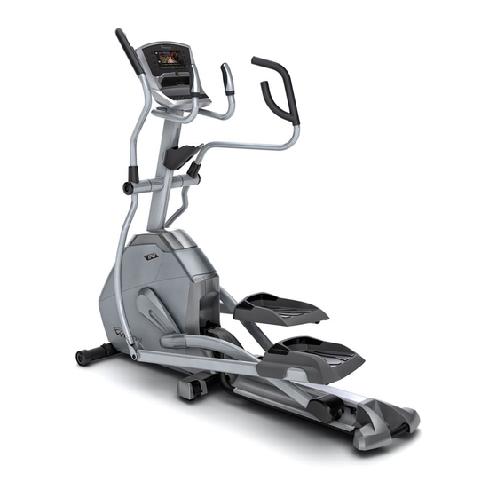
- Page 23 UPPER HANDLEBAR PULSE GRIPS XF40 WATER BOTTLE HOLDER WARNING CONSULT A PHYSICIAN PRIOR TO USING ANY LOWER HANDLEBAR EXERCISE EQUIPMENT. POSSIBILITY OF SERIOUS INJURY IF EQUIPMENT IS USED IMPROPERLY. READ INSTRUCTION MANUAL BEFORE USING. KEEP CHILDREN OFF AND AWAY FROM THIS EQUIPMENT. FOR CONSUMER USE ONLY.
- Page 24 PULSE GRIPS UPPER HANDLEBAR WATER BOTTLE HOLDER WARNING CONSULT A PHYSICIAN PRIOR TO USING ANY EXERCISE EQUIPMENT. POSSIBILITY OF LOWER HANDLEBAR SERIOUS INJURY IF EQUIPMENT IS USED IMPROPERLY. READ INSTRUCTION MANUAL BEFORE USING. KEEP CHILDREN OFF AND AWAY FROM THIS EQUIPMENT. FOR CONSUMER USE ONLY.
- Page 25 PULSE GRIPS UPPER HANDLEBAR WATER BOTTLE HOLDER WARNING CONSULT A PHYSICIAN PRIOR TO USING ANY LOWER HANDLEBAR EXERCISE EQUIPMENT. POSSIBILITY OF SERIOUS INJURY IF EQUIPMENT IS USED IMPROPERLY. READ INSTRUCTION MANUAL BEFORE USING. KEEP CHILDREN OFF AND AWAY FROM THIS EQUIPMENT. FOR CONSUMER USE ONLY.
- Page 26 ASSEMBLY WARNING There are several areas during the assembly process when special attention must be paid. It is very important to follow the assembly instructions correctly and to make sure all parts are firmly tightened. If the assembly instructions are not followed correctly, the elliptical could have frame parts that are not tightened and will seem loose and may cause irritating noises.
- Page 28 WARNING TO REDUCE THE RISK OF BURNS, FIRE, ELECTRICAL SHOCK OR INJURY TO PERSONS: • Keep power cord away from heated surfaces. Do not carry this unit by its supply cord or use the cord as a handle. • Do not use other attachments that are not recommended by the manufacturer. Attachments may cause injury. •...
- Page 29 DANGER TO REDUCE THE RISK OF ELECTRICAL SHOCK: Always unplug the elliptical from the electrical outlet immediately after using, before cleaning, performing maintenance and putting on or taking off parts. WARNING • To reduce the risk of burns, fire, electrical shock or injury to persons: •...
- Page 30 Read all instructions before using this elliptical. It is the responsibility of the owner to ensure that all users of this elliptical are adequately informed of all warnings and precautions. If you have any questions after reading this manual, contact your authorized Vision Fitness ®...
- Page 32 ELLIPTICAL OWNER’S MANUAL Read the ELLIPTICAL GUIDE before using this OWNER’S MANUAL.
Need help?
Do you have a question about the XF40 and is the answer not in the manual?
Questions and answers