Table of Contents
Advertisement
Advertisement
Table of Contents

Related Manuals for Topcon LS-B4


Summary of Contents for Topcon LS-B4
- Page 1 INSTRUCTION MANUAL LASER SENSOR LS-B4...
- Page 3 FOREWORD FOREWORD Thank you for purchasing the TOPCON LS-B4 Laser Sensor. For superior product performance, please read these instructions carefully and keep them in a convenient place for future reference. GENERAL HANDLING PRECAUTIONS Before starting work or operation, be sure to check that the system is functioning properly.
- Page 4 FOREWORD Protecting the instrument from water damage. When washing the instrument, avoid spraying it with a high pressure stream of water from a water hose. The inside of the instrument will be damaged by the water. This instrument is designed based on the International Standard IPX 6, but it is not protected from a high pressure water stream or submergence.
- Page 5 FOREWORD Using Connector Caps When the external connector is not being used, make sure the protective is placed over it as shown below. Keep the cap over the charging connector on the DB-54C rechargeable battery pack except when charging the batteries. DB-54C+BT-54Q Charging connector cap External connector cap...
-
Page 6: Safety Notices
FOREWORD SAFETY NOTICES In order to encourage the safe use of products and prevent any danger to the operator and others or damage to property, important warnings are put on the products and inserted in the instruction manual. We suggest that everyone understand the meaning of the following symbols and notices before reading the Safety Cautions and text. -
Page 7: Safety Cautions
• There is a risk of fire, electric shock or physical harm if you attempt to disassemble or repair the instru- ment yourself. This is only to be carried out by TOPCON or an authorized dealer, only ! • Risk of fire or electric shock. -
Page 8: Exceptions From Responsibility
FOREWORD USER Wear the required protectors (safety shoes, helmet, etc.) when operating. EXCEPTIONS FROM RESPONSIBILITY 1)The user of this product is expected to follow all operating instructions and make peri- odic checks of the product’s performance. 2)The manufacturer, or its representatives, assumes no responsibility for results of a faulty or intentional use or misuse including any direct, indirect, consequential damage, and/or loss of profits. -
Page 9: Table Of Contents
FOREWORD CONTENTS FOREWORD ..........1 GENERAL HANDLING PRECAUTIONS . - Page 10 5.1.1 Connecting the RD-2 and LS-B4 ....... . . 5-2...
-
Page 11: Standard System Components
Warranty card 1vol. 1vol. 1vol. Make sure that all of the above items are with the instrument when purchased. If you purchased the LS-B4 Laser Tracker package (C model) all package components are stored in the incleded soft carrying case. -
Page 12: Nomenclature And Functions
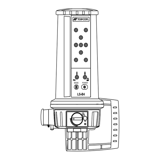
Detector Display Mode 2 indicator / Mode 1 indicator / Rotating Laser(RL) Battery Status Light Laser sensor(LS) Battery (operates with specific Topcon laser models only) Status Light Mode Selection Switch Power Switch Battery Holder Lock Hand Grip / Mast Clamp... -
Page 13: Functions
This instrument can also be used in conjunction with the Trackerjack (Laser Tracker package, C model) as the primary rotating laser receiver for any Topcon equipment automation system (System Five, System Four, Touch Series 5, etc). -
Page 14: Connection Diagram
1NOMENCLATURE AND FUNCTIONS 1.3 Connection diagram D-size Dry cell Battery Pack Hand Grip / Mast Clamp BT-54Q LS-B4 Battery cable PC-18 (#9060-5033) (Optional accessory) Remote display RD-2 (Optional accessory) Battery cable PC-20 (#9060-5087) Battery holder (Optional accessory) DB-54 Battery holder... -
Page 15: Preparing For Use
2 PREPARING FOR USE 2 PREPARING FOR USE 2.1 Handling the battery 2.1.1 Dry battery Installing the battery Turn the lock konb on the battery holder (DB-54) to “OPEN” and remove it. Insert the two D-size dry cells, matching them with the positive and negative illustrations. -
Page 16: Chargable Battery
2 PREPARING FOR USE 2.1.2 Chargable battery Installing Remove DB-54C holder by turning the lock knob to “OPEN”. Insert BT-54Q battery pack into the holder. Insert the holder to the instrument and turn the lock knob to “LOCK”. Charging Plug the AD-9B/7C AC/DC convertor into the charging connector on the holder. Plug the convertor into an electrical outlet. - Page 17 •You can charge the battery pack(BT-54Q) while the battery holder(DB-54C) is installed on the instrument(LS-B4). •Dry batteries (two D-cell alkaline) can be used by removing the battery pack (BT-54Q) and placing...
- Page 18 2 PREPARING FOR USE Note • Recharging should take place in a room with an ambient temperature range of 10°C to 35°C (50°F to 95°F). • Exceeding the specified charging time may shorten the life of the battery and should be avoided if possible.
- Page 19 Replace the empty battery holder. Then, turn on the power again. Do not use the LS-B4 without the battery cover or battery holder installed. Without it installed, water may enter the instrument and cause a malfunction.
-
Page 20: Power Switch On And Off
2 PREPARING FOR USE 2.2 Power switch ON and OFF The power can be turned on by pressing the POWER switch. The Mode 1 indicator will illuminate. Pressing the POWER switch again turns off the power. Mode 1 indicator Power switch... -
Page 21: Battery Status Light
2 PREPARING FOR USE 2.3 Battery Status Light The LS-B4 has two separate low battery indicator lights, one for the LS-B4 batteries and one for indicating low batteries in the rotating laser *. LS-B4 (LS Battery Status Light) If the LS-B4 battery status light (Mode 1 indicator) blinks, replace the batteries with new ones or charge the battery pack. -
Page 22: Rotating Laser Height Alert Warning
If the display illuminates as shown above, the rotating laser has been disturbed and a substantial change in its position could have occurred. This change has been detected by the LS-B4. The laser position should be checked to prevent possible erroneous measurements. -
Page 23: Double Power Supply Connection Warning
When this warning is displayed, immediately turn off the power and remove the batteries from the battery holder. Replace the empty battery holder. Turn on power again. Do not use the LS-B4 without the battery cover or battery holder installed. Without it installed, water may enter the instrument and cause a malfunction. -
Page 24: Power Saving Mode And Auto Shut-Off
To return to full power, vibrate the LS-B4 by moving the equipment where it is mounted. Auto Shut-Off If the LS-B4 does not receive a laser signal within an one hour time period, power is automatically shut off. To restore power, press the POWER switch. Display of Power Saving Mode and Auto Shut Off... -
Page 25: Changing On-Grade Tolerance (Mode Selection)
2 PREPARING FOR USE 2.5 Changing On-Grade Tolerance (Mode Selection) Two on-grade tolerance (height of the on-grade indication) are available. Select Mode 1 (±6mm) and Mode 2 (±20mm) according to the work specifications. Changing mode Press the mode selection switch. Mode 1 and Mode 2 are alternately selected and indicated on the display. -
Page 26: Installing On The Equipment
2 PREPARING FOR USE 2.6 Installing on the equipment Use the clamp on the rear of LS-B4 to mount it to a mast installed on the equipment. LS-B4 Mast Speciation Clamp Knob Shape: Round Bracket Size: 1.5”~2” diameter (38~51mm) Mast... -
Page 27: Display Information
The LS-B4 display is a high-intensity colored LED array that provides a visual guide for positioning the cutting edge of the machine to a predetermined on-grade elevation. As the LS-B4 is moved through path of the laser beam, the display will provide seven channels of information as described on the next page. - Page 28 2 PREPARING FOR USE This illustration depicts the reaction of LS-B4 display as the sensor is moved down through the path of a rotating laser.* Blade direction to achieve DOWN DOWN DOWN GRADE on-grade* LED Color Yellow Green LED display...
-
Page 29: Establishing On-Grade Position
3 ESTABLISHING ON-GRADE POSITION 3 ESTABLISHING ON-GRADE POSITION Position a rotating laser as shown below and turn on the laser. Rotating laser Raise or lower the machine blade to position the cutting edge at the desired grade elevation. Blade Desired grade elevation... - Page 30 LS-B4 Turn on the LS-B4 and then select the tolerance (mode). Keep the machine blade motionless and raise or lower the LS-B4 until the three center ON-GRADE lights are flashing. This is the ON-GRADE position. Securely clamp the LS-B4 in place. The reference position has been set.
-
Page 31: Care & Cleaning
4 CARE & CLEANING 4 CARE & CLEANING • Always clean the instrument after use. • Remove the dust using a brush, then wipe off with a soft cloth. • Never use thinner or benzine to clean the surface of a receiving window or any plastic parts. -
Page 32: Optional Accessories
5 OPTIONAL ACCESSORIES 5 OPTIONAL ACCESSORIES •Remote Display RD-2 •Power Cable PC-20 (#9060-5087) •Power Cable PC-18 (#9060-5033) •Joint Cable JC-7 (#9063-1035-20) -
Page 33: Connection To Other Instruments
Connect LS-B4 to other instruments and power supply as follows. When connecting LS-B4 to the battery of a machine, connect the red clip of the power cable (PC-18 or PC-20) to the positive side of the battery and the black clip to the negative side (or ground). -
Page 34: Using The Machine Battery To Power Ls-B4
5 OPTIONAL ACCESSORIES 5.1.2 Using the machine battery to power LS-B4 PC-20 (#9060-5087) When the LS-B4 is connected to the machine's Black battery, power automatically supplied to the LS-B4 and the power switch is disabled. Battery of the machine... -
Page 35: Remote Display
5 OPTIONAL ACCESSORIES 5.2 RD-2 Remote Display The RD-2 allows the LS-B4 display to monitored in a convenient location, such as in the cab of a dozer. Nomenclature 5.2.1 Mode indicator Power switch Connector for LS-B4 Power supply connector Display... -
Page 36: Installation
5 OPTIONAL ACCESSORIES 5.2.2 RD-2 Installation On a vertical or horizontal surface of a machine, install RD-2 using its optional mounting hardware as shown below. Installation on horizontal surface Installation on vertical surface RD/IR-2 adapter RD/IR-2 adapter The RD/IR-2 adapter is an optional accessory... -
Page 37: Display
5 OPTIONAL ACCESSORIES 5.2.3 RD-2 Display This illustration depicts the reaction of the RD-2 display as the LS-B4 sensor is moved down through the path of a rotating laser.* Blade direction to achieve on-grade* DOWN DOWN GRADE LED Display Display steps:... -
Page 38: Using The Rd-2
Set up a rotating laser, turn it on and position the blade of the machine at the references elevation as described on page 3-1. Mount the LS-B4 on the mast and connect the LS-B4 to the RD-2 with the JC-7 junction cable. - Page 39 There are four mode indicators (1~4) on the RD-2 display. Only two mode indicaters(1~2) are used when the LS-B4 is connected. Move the LS-B4 up and down until the RD-2 display shows “ON GRADE”. Tighten the clamp knob of the LS-B4 securely.
-
Page 40: Specifications
6 SPECIFICATIONS 6 SPECIFICATIONS Vertical Sensing Range : 200mm / 7.875 inches Horizontal Sensing Radius : 360 degrees ON GRADE Tolerance : (Using Topcon RL-H1Sa laser) Modes On-Grade Tolerance Mode1 ±6mm / 0.02ft Mode2 ±20mm / 0.06ft *Tolerance may vary depending on laser detecting distance, rotating laser being used or atmospheric conditions. - Page 41 6 SPECIFICATIONS Power Supply : DC10V~28V (Battery of the machine) (External battery) : 2 D-Type Dry batteries(DC3V) (Internal battery) (D-Type Ni-MH battery can be used) Battery pack BT-54Q Operating Time : Approximately 60 hours (+20°C / +68°F) With alkaline batteries •The dry batteries included are provided exclusively for operation check and could have a shorter life.
- Page 42 TOPCON (GREAT BRITAIN) LTD. TOPCON AMERICA CORPORATION HEAD OFFICE CORPORATE OFFICE Topcon House Kennet Side, Bone Lane Newbury Berkshire RG14 5PX 37 West Century Road, Paramus, New Jersey 07652, U.S.A. U.K. Phone: 001-44-1635-551120 Fax: 001-44-1635-551170 Phone: 201-261-9450 Fax: 201-387-2710 www.Topcon.com TOPCON SINGAPORE PTE.
Need help?
Do you have a question about the LS-B4 and is the answer not in the manual?
Questions and answers